Week 4 Challenge : CFD Meshing for BMW car
AIM:
To create a Fluid domain for the given vehicle and mesh according to the parameters given.
the given vehicle model contains many geometric errors and intersection errors, we are to check for the errors and correct them according to the requirements.
once after completing the geometric corrections we are to assign the vehicle and its components to respective ids.
the given model of the vehicle is in symmetry, so we can do a part correction of the errors and mirror the other face of the vehicle.
the mesh parameters for the given vehicle is stated as:
Target lengths for the different parts of a model are as follow:
- Body - 3 mm
- Lights - 4 mm
- Grills - 1 mm
- Rims and Tyres - 2 mm
- Optical Rear view mirror - 2 mm
- Window - 2 mm
- Silencer - 3 mm
- Logo - 1 mm
................................................................................................................................................................................................................................................................................................................................................................
FIRST IS TO TAKE IN THE VEHICLE MODEL AND CHECK THEM FOR ERRORS:
The vehicle model is taken in and the model shows much errors like single cons and triple cons that require correction.
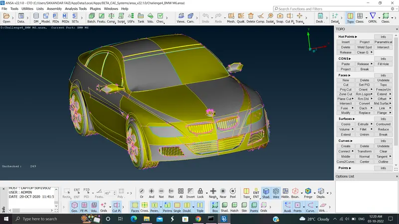
we can find many red, blue lines which represents the errors as stated, so we first have to get in to correct them.
the resolution of the given model seems out of shape, we are to get it corrected for smoother geometry.
the length tool in perimeter helps in achieving it.
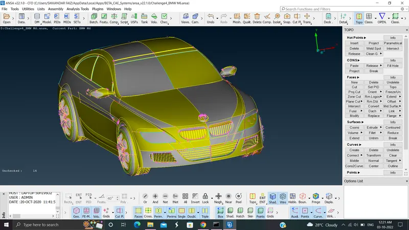
once then we are to cut off the given model into two because the part are symmetric and can be mirrored if even one part is corrected. its an easy way to achieve the required model with a few minutes spared.
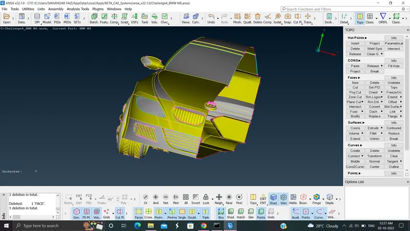
once completing the cutting off we then move on to correcting the single cons and triple cons in all the components.
we first get in to the grill components and correct them without the single cons and triple cons and free of interference errors too.
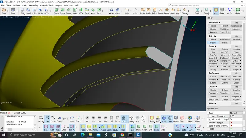
the project tool, faces tool, curves tool, cons tool plays a vital role in achieving the error correction in grills.
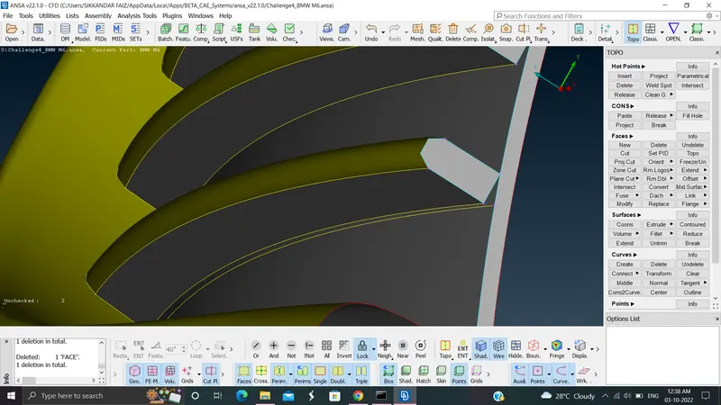
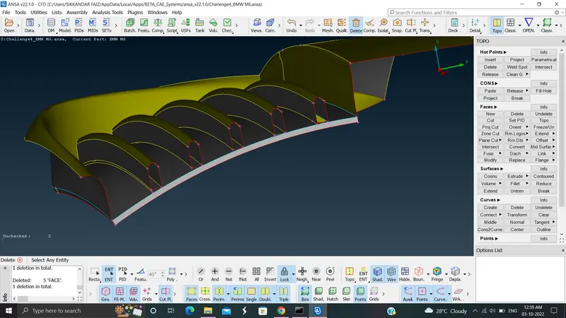
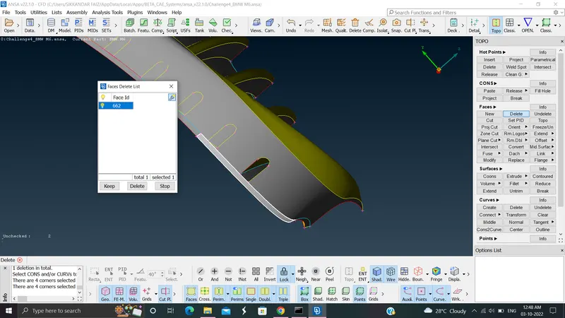
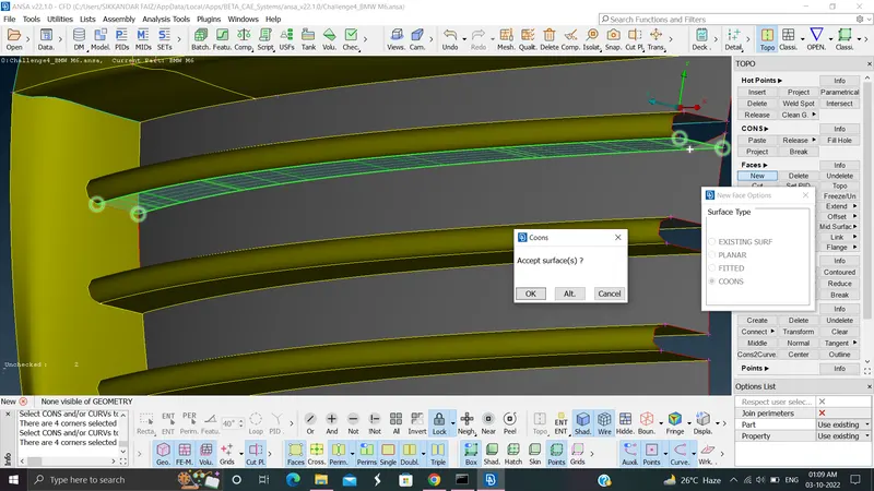
some of the glimpse of the error correction done in one of the grills is shown above.
the other two grills are shown below:
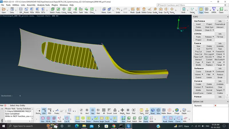
the second grill has to corrected with the help of all the above tools and intersect plays a major role too.
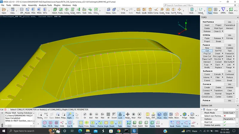
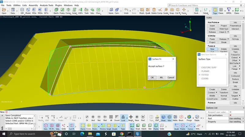
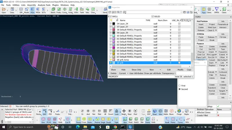
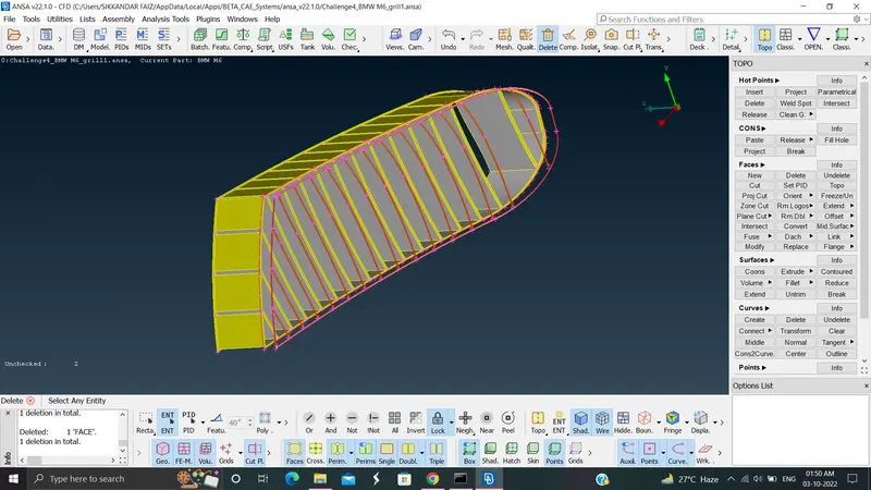
then the third grill:
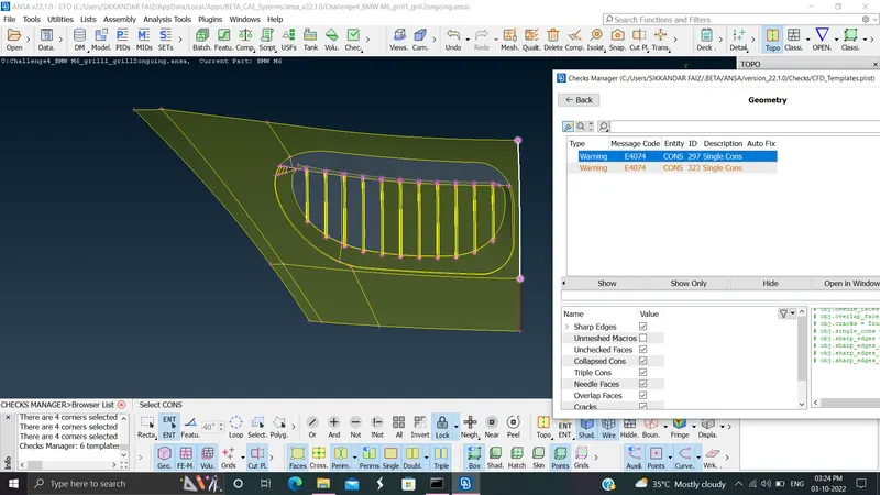
the third one looks as such after corrections.
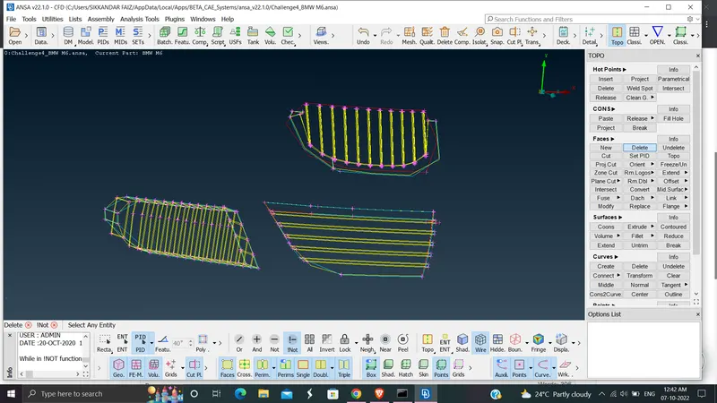
the whole pic of grills before and after correction:
before:
after:
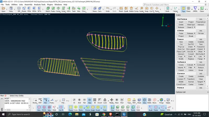
the grill set has been corrected, now the other sections:
the logo:
before:
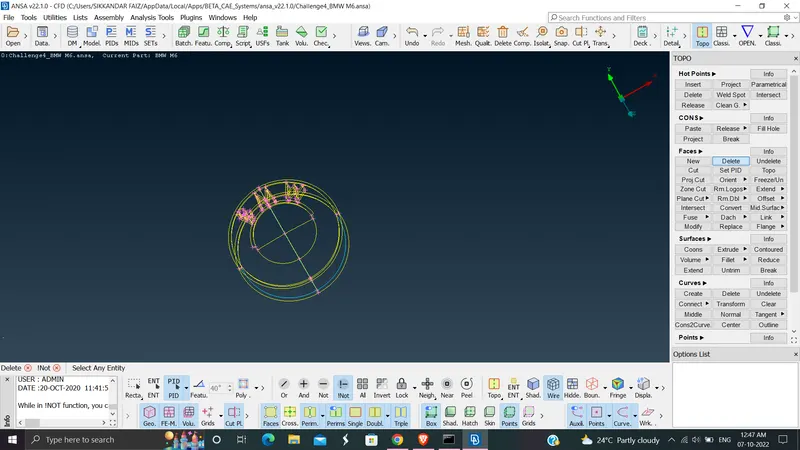
after:
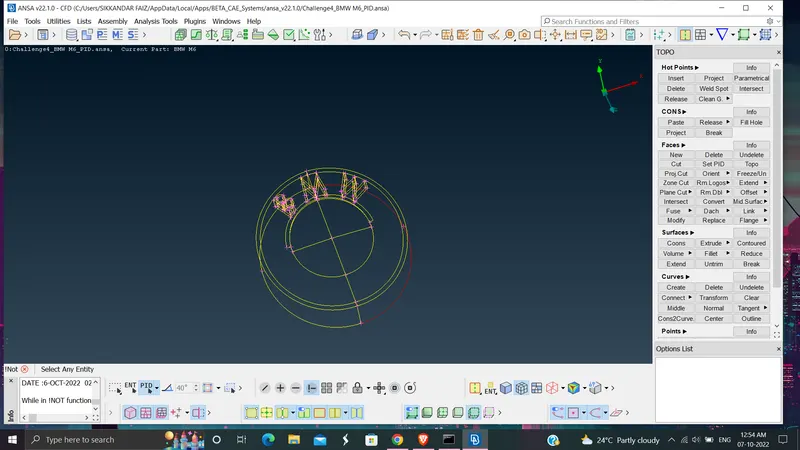
there is only a single con and it has to be there because we cut off the other part of the car.
likewise the window, optical rear view mirror, rims and tyres are corrected from
this:
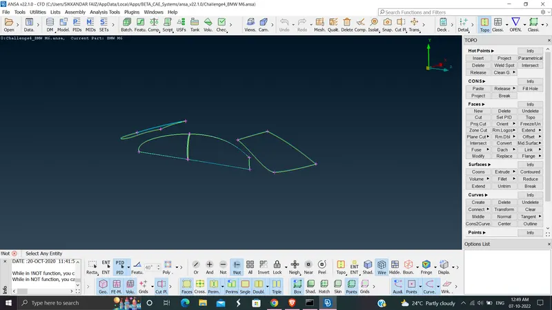
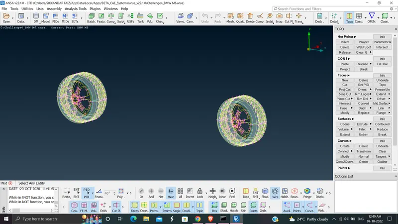
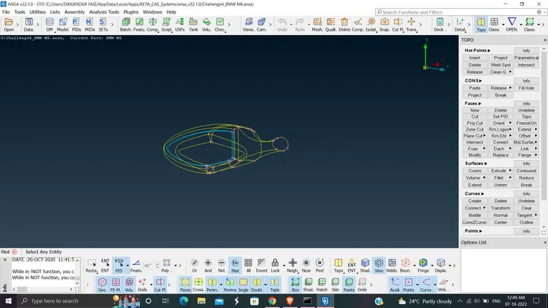
to:
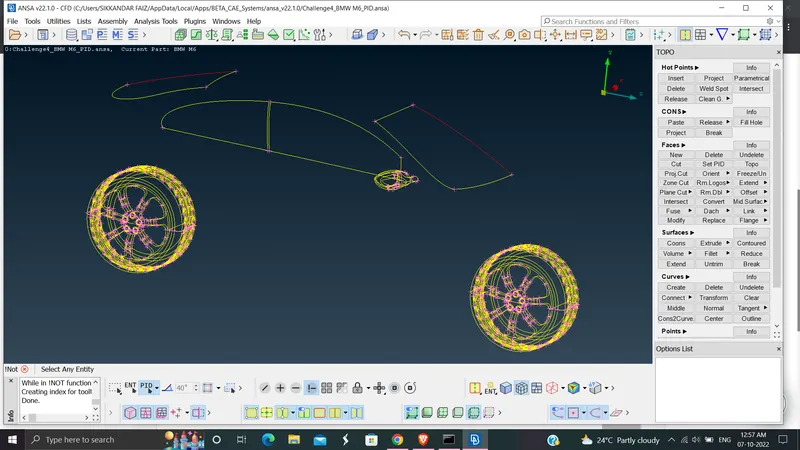
and so the body, silencer, and the lights have been corrected:
from this:
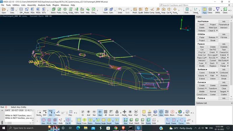
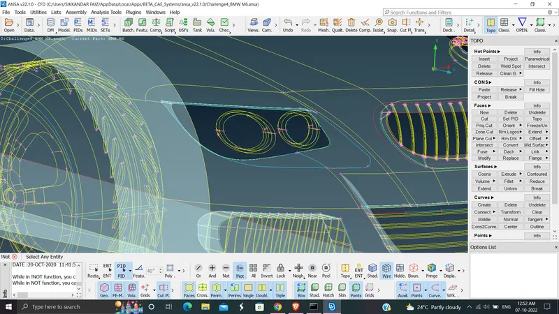
to:
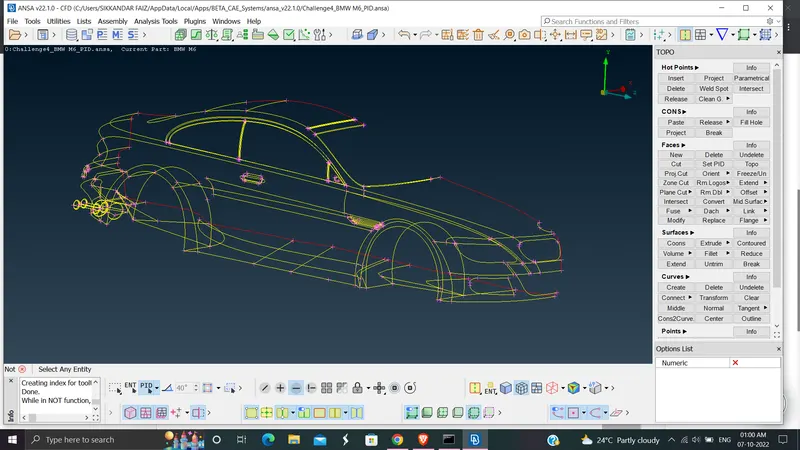
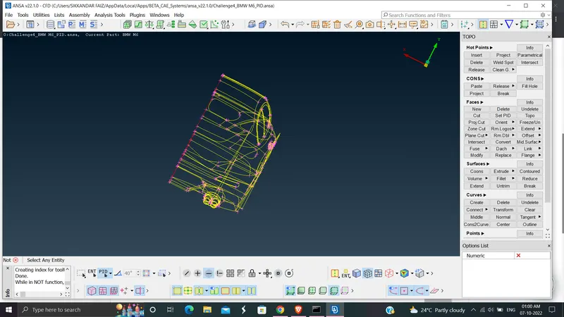
like before a total glimpse of the error corrections of the components of the vehicle is shown above.
completing all the geometric corrections we are to assign the components of the vehicle according to their identification(PIDS).
once then check for geometric errors and for intersection errors in checks manager:
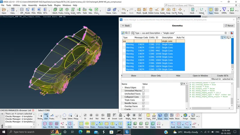
we can see all the single cons because we are to fit another face of the car and some unavoidable concave and mixed cons because of the curved geometry of the components.
................................................................................................................................................................................................................................................................................................................................................................
PROPERTY IDENTIFICATION ASSIGNING(PIDS):
the components are assigned as:
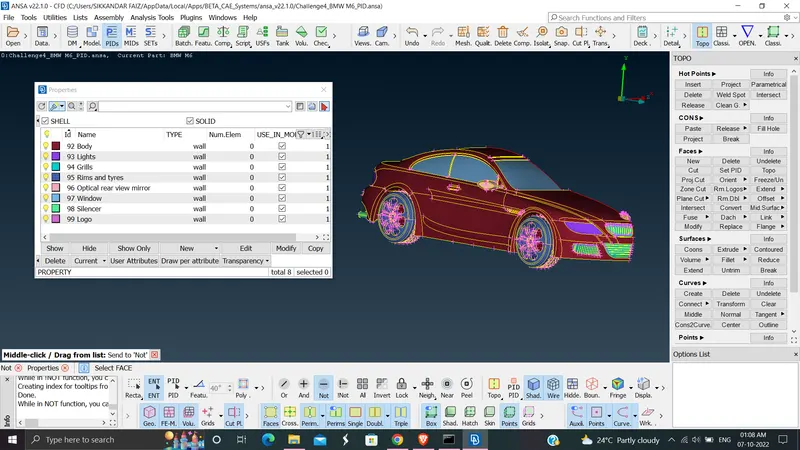
the PIDS help in easy meshing and in component identification.
................................................................................................................................................................................................................................................................................................................................................................
MESHING OF INDIVIDUAL COMPONENTS ACCORDING TO THE GIVEN TARGET LENGTHS:
The meshing of the grill elements and the logo require a target length of 1mm. we have taken the min and max target lengths to be 0.9 and 1.1 mm. before getting into the meshing we need to provide quality parameters.
Quality parameters:
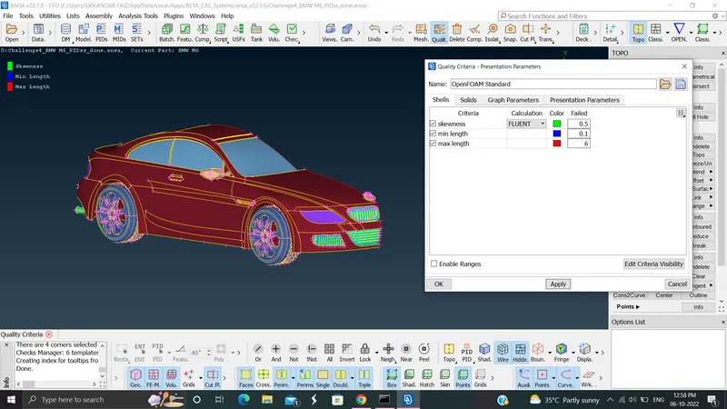
the skewness, min and max length has been assigned acording to the requirement.
once then we are to mesh in the components, we take the grills for meshing according to the given above target length.
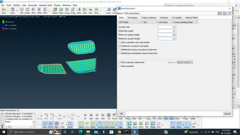
setting up the auto cfd spacing we ge into the meshing cfd visible.
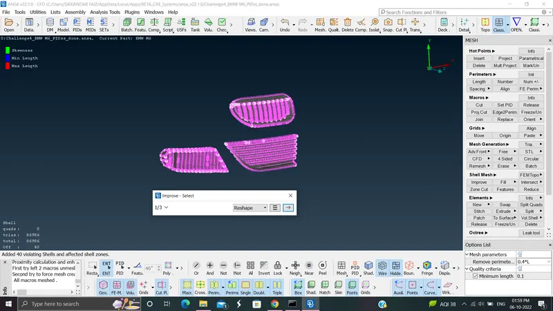
once meshing is done the elements that doesn't go according to the quality criteria is corrected, reconstructed for better result.
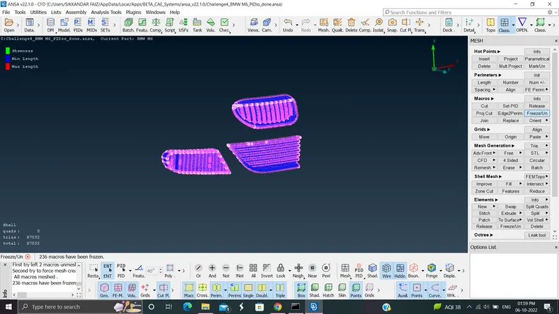
once done meshing without any off elements freeze it before getting to other components meshing.
then we move onto the logo which goes exactly with same target length.
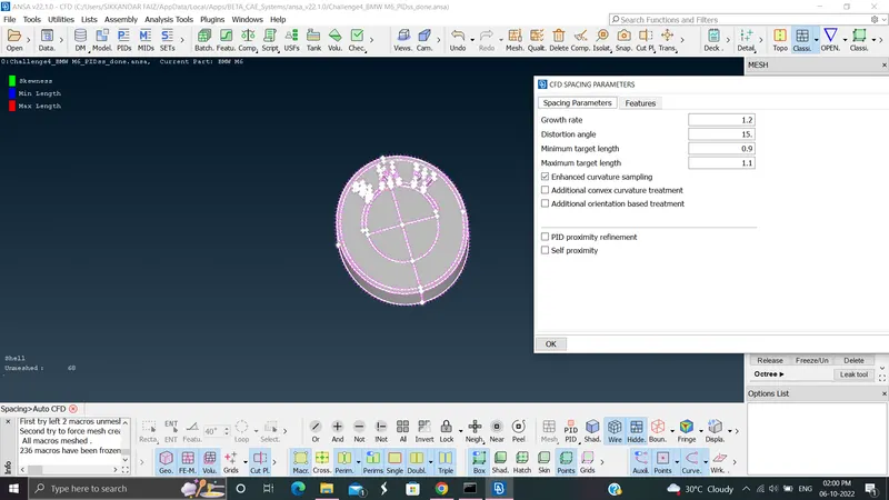
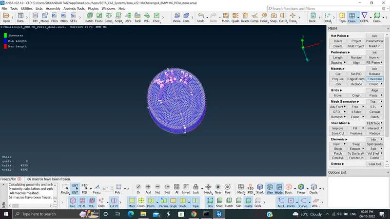
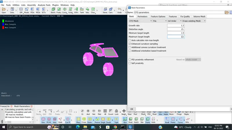
then towards the 2 mm meshing of the window, rear view mirror and the rim tyre.
we are providing a min and max target length of 1.9 and 2.1 mm for the correct meshing.
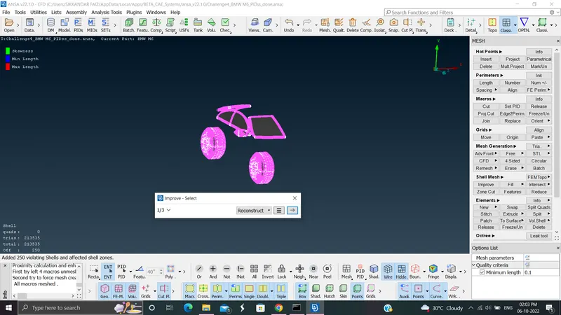
after reconstructing the off elements
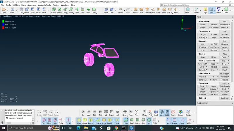
the exhaust system and the body is to be meshed with a target length of 3 mm, the min and max target length we provide are 2.9 and 3.1 mm
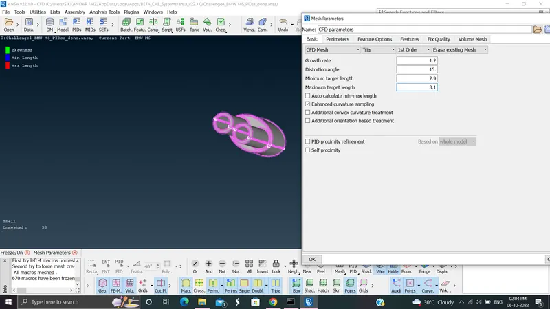
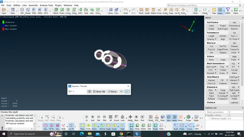
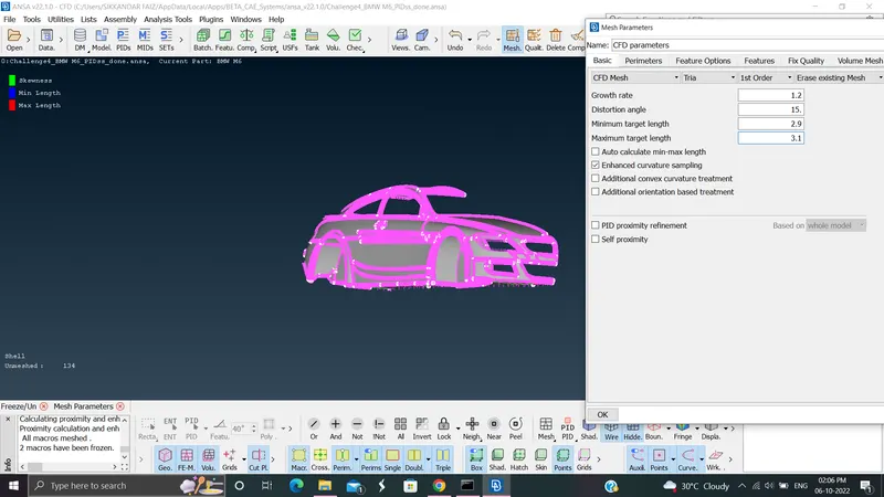
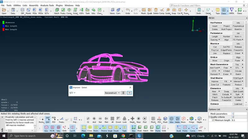
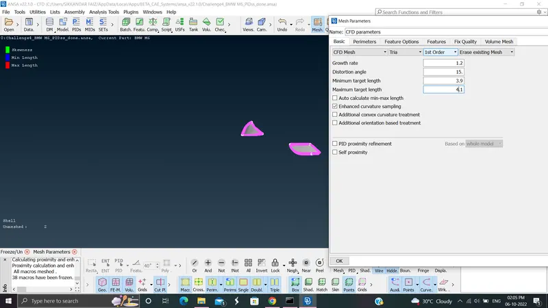
completing the off elements in body and exhaust we move on to the lights which has to be meshed with 4 mm target length.
we provide min and max TL as 3.9 and 4.1 mm
the completely meshed surface of the components are visible as below:
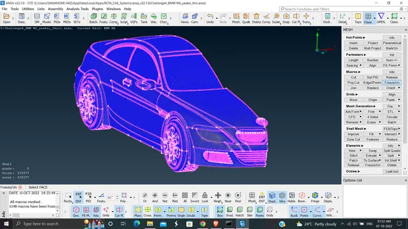
unfreeze it to process for the mirror option that is to create the symmetrical other face of the car.
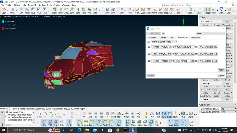
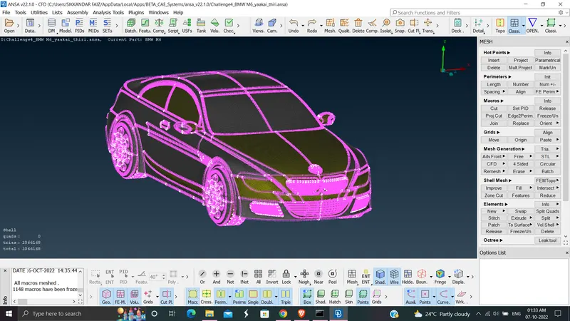
once done we can find few geometric errors, they are corrected with the help of paste tool in the cons
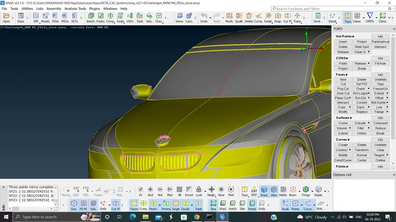
then go for a geometric check in checks manager to be sure of errors are all corrected.
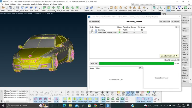
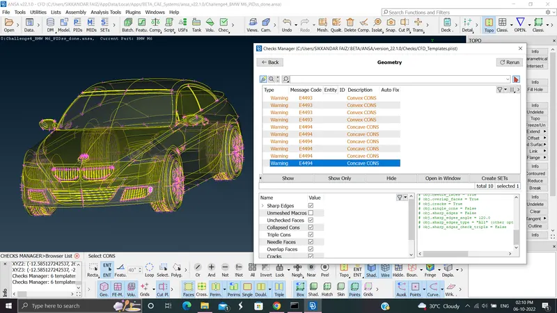
we can find only the unavoidable concave cons because of the curved geometry of few of the components.
................................................................................................................................................................................................................................................................................................................................................................
WE ARE TO MAKE A FLUID DOMAIN OR A WIND TUNNEL AND SURFACE MESH IT TOO.
we are to create a tunnel around the whole car model, for which we need to create some reference points around the car model.
the points tool is very much helpful in creating the reference points.
a point is created at centre of the car model,
the total length of the car is taken as x,
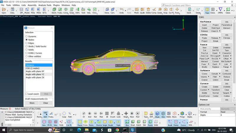
x = 1310 mm.
we create a point below the point created at the centre and the distance provided is 1310mm
the point on the front of the car shouls be at 4 times the length of car so 4*x,
4*1310 = 5240 + the distance between the centre of car to front face of car (655 mm) = 5895 approximate = 5900 mm.
so we keep a point in front of car taking the centre bottom point created previously.
similarly 6*1310 behind the car, so 7860mm + 655 = 8515 mm.
then we move the points to the side which has to be 1310 mm to the sides. two points with the previously created front and back points at centre.
they are about 1540 mm away from the middle once.
then create a floor with the help of curves and faces tool.
we need to make a top face to so we offset the bottom face to a distance of -5550 mm from bottom.
finally we get:
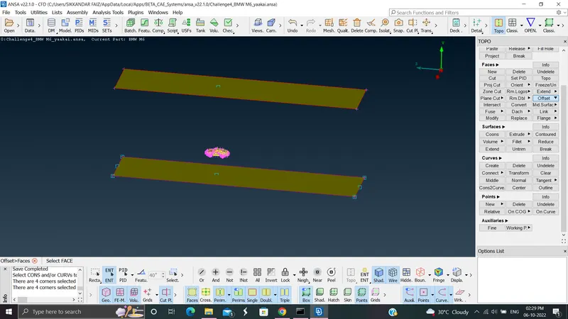
we are to assign them pids in the PID TOOLBOX.
we are to create a 20 mm mesh at the bottom face and 100 mm mesh at the top face.
we can create side faces with help of bottom and top face.
the bottom face is meshed as:
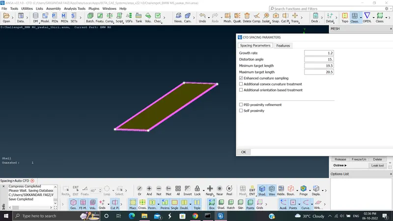
with min and max target length as 19.5 and 20.5 mm
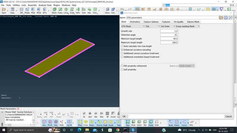
likewise the top face is created with min and max target lengths as 99.5 and 100.5 mm
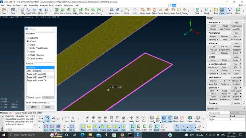
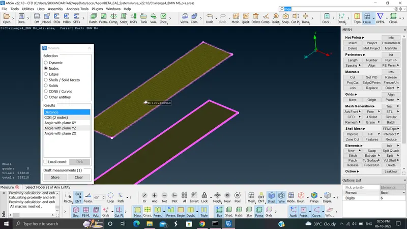
the side face profile has to be meshed with respect to the bottom and the top face. it needs to have its starting perimeter to be 20mm and gradually enlarge to 100 mm.
so we create spacing manually.
we provide the d start value as 20 mm and d limit as 100 mm.
then we give the respective edges for it to form.
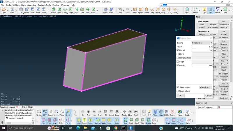
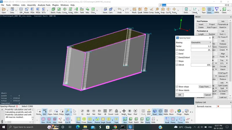
then like always we go for cfd visible.
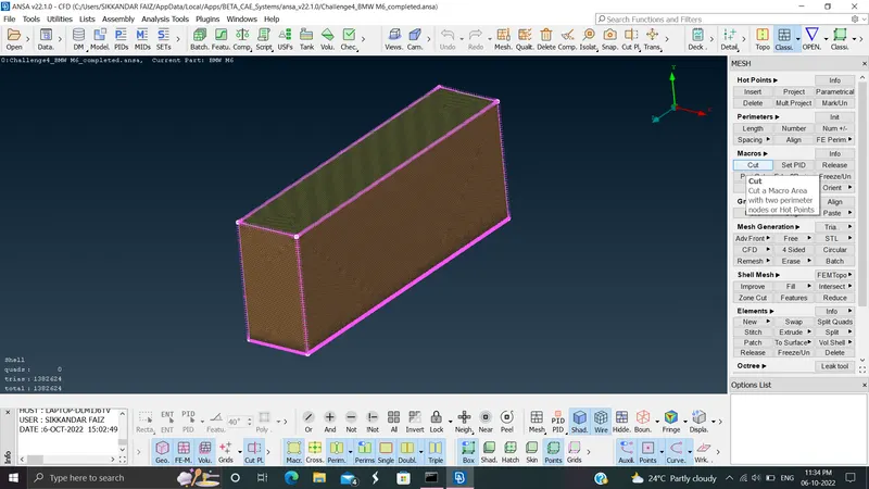
the final view will be as such once after assigning the components and all the tunnel sides to their respective PIDs.
................................................................................................................................................................................................................................................................................................................................................................
RESULT:
hope the final model has satisfied the requirements of the question.
CONCLUSION:
The given model is checked for geometric errors, interference errors.
then the PIDS have been assigned and the meshing of individual components has been done according to required target lengths.
the wind tunnel is created and the meshing has been done on the tunnel too.
LINK: https://drive.google.com/file/d/1PJBPv4jvkJ2EC3aNjyAFMPzd-aDOsA8H/view?usp=sharing
THANK YOU.