Week 4 Challenge : CFD Meshing for BMW car
Aim:
For the given model, check and solve all geometrical errors on half portion and Assign appropriate PIDs. Perform meshing with the given Target length and element Quality criteria. After meshing the half model, Do symmetry to the other side and V.mesh to wind tunnel and car geometry
- Target lengths for the different parts of a model are as follow:
- Body - 3 mm
- Lights - 4 mm
- Grills - 1 mm
- Rims and Tyres - 2 mm
- Optical Rear view mirror - 2 mm
- Window - 2 mm
- Silencer - 3 mm
- Logo - 1 mm
Procedure:
A)Topo Clearance :
- Open the model, Change it to PID mode from ENT mode.
- Check in Wireframe mode, to view the number of single cons of triple cons
- Apply topo feature to the entire model and solve the triple cons.
- The Cons are unshaped ( not fine ) throughout the entire model. So, Cons resolution has to be increased.
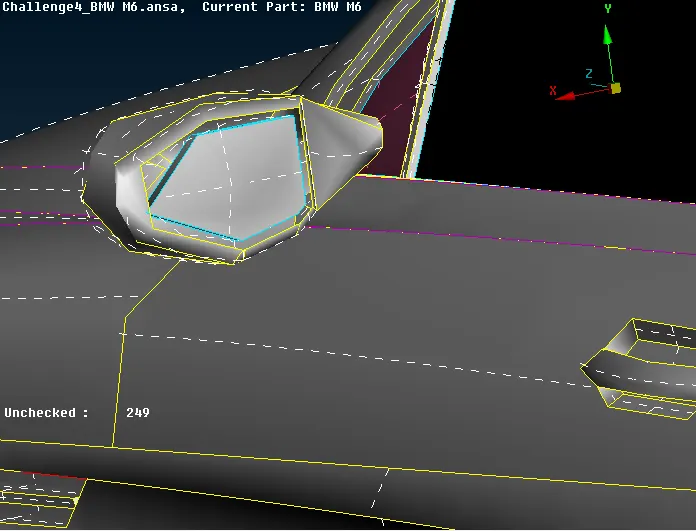
- Among the various options, FINE option can be used but for the entire model it is not advised as it consumes lot of time.
- Short cut method: Under Mesh Deck > Apply Length as 1 mm selecting the entire model.
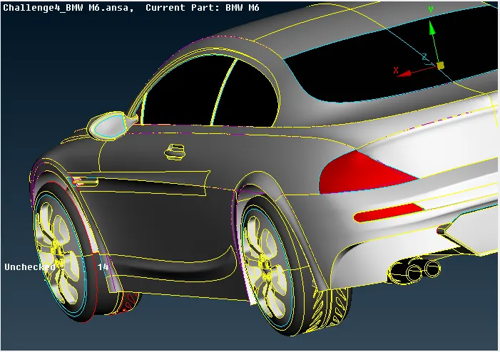
- Check Single cons and triple cons disabling shadow and enabling wireframe mode to rectify.
- Selecting half of the model to delete and execute the symmetry to save time
- Next is the topo cleanup to make entire model as uni-volume
- As the geometry is symmetrical, intially the topo clean up is performed with one half of the model and the made symmetrical using symmetry option.
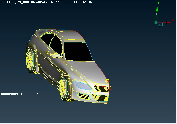
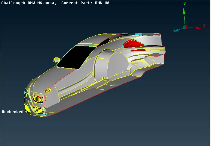
- Deleting unnecessary surfaces from inside so that outside features are not affected while creating as a single connected volumes.
- Various tools for topo cleanup activities used are:1. Delete 2. Create faces using fitted and coons 3. Paste 4. Project 5. Multi Project 6. Extend 7. Inserting hot points 8. Cons2Curv 9. Measure 10. Uncut
B)Assigning PIDs, Setting Quality Criteria & Surface Meshing:
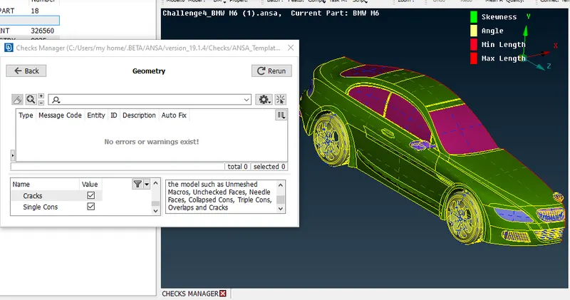
- Once the topo clean up is done and verified the geomtery check for single and triple cons
- next follows assigning PIDs
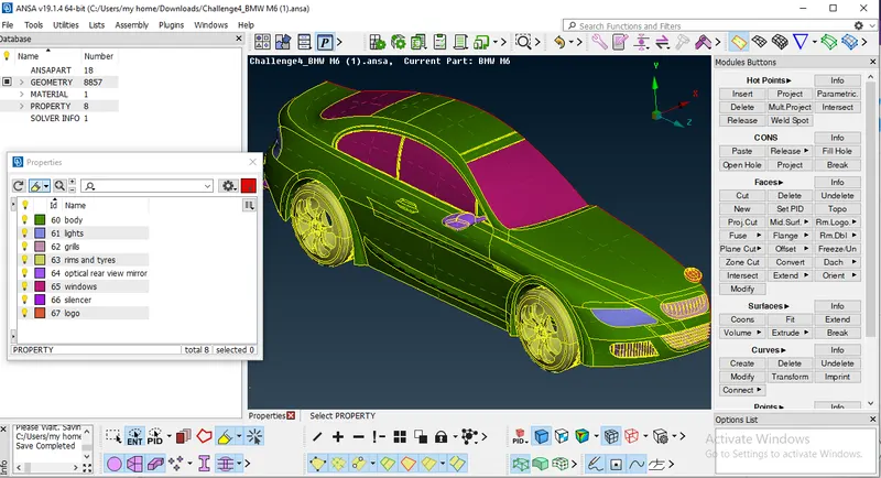
- After Assigning PIDs, Surface mesh Operations are initiated for the individual PIDs as per the given mesh target lengths.
- Mesh Element: Tria; Minimum length, maximum length, target length, Perimeters & macros length and at last spot mesh selecting the PIDs.
- Quality criteria are extracted for PIDs individually through the Measure option identifying minimum & maximum distances in each PIDs
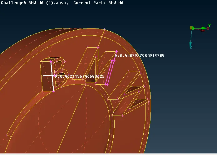
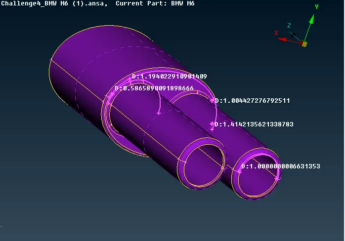
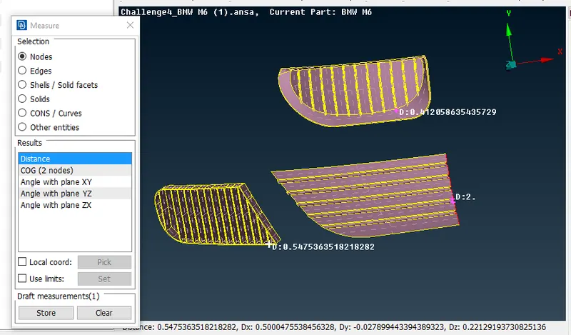
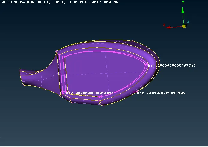
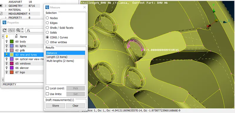
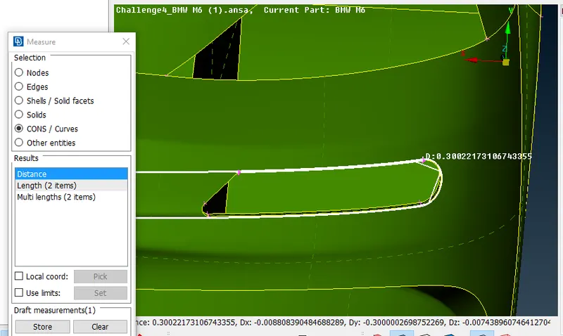
B1) Solving Off Elements: (Using Reconstruct, Move, Smooth & Split )
- Logo : Target Length : 1mm (QC 0.3 & 2)
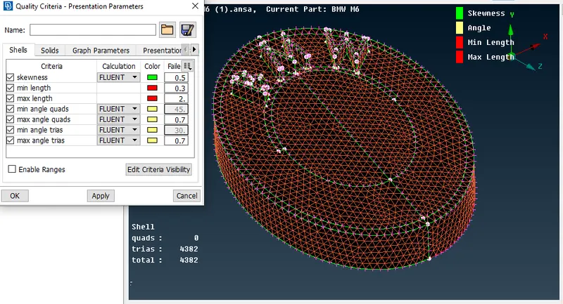
- Grills section: Target Length : 1mm (QC 0.3 & 2)
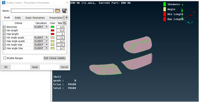
- Window : Target Length =2mm (QC 1 & 3)
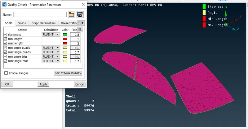
- Rims & Tyres ( Target Length: 2mm, Q&C 0.3 & 2) )
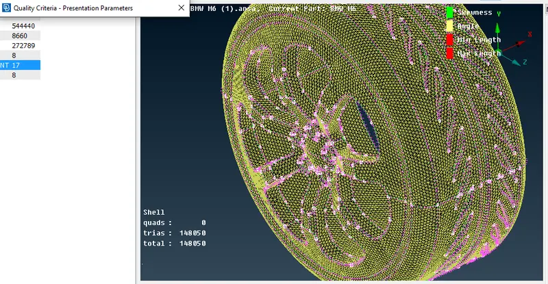
- Optical Rear View Mirror ( Target Length: 2mm, Q&C 1 &3 )
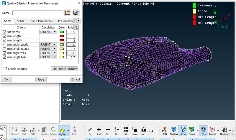
- Lights ( Target Length : 4mm, Q&C 3&5)
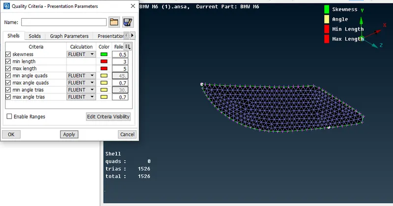
- Silencer (Target Length: 3mm, Q&C 1&5)
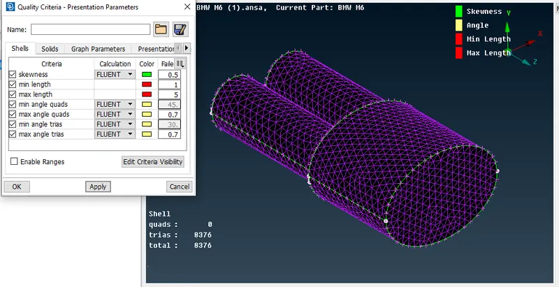
- Body (Target Length : 3mm, QC 1 & 6)
- Using freeze option, the other PIDs are locked and then the body mesh is performed by applying Length parameters alone to prevent mesh loss due to common area macros.
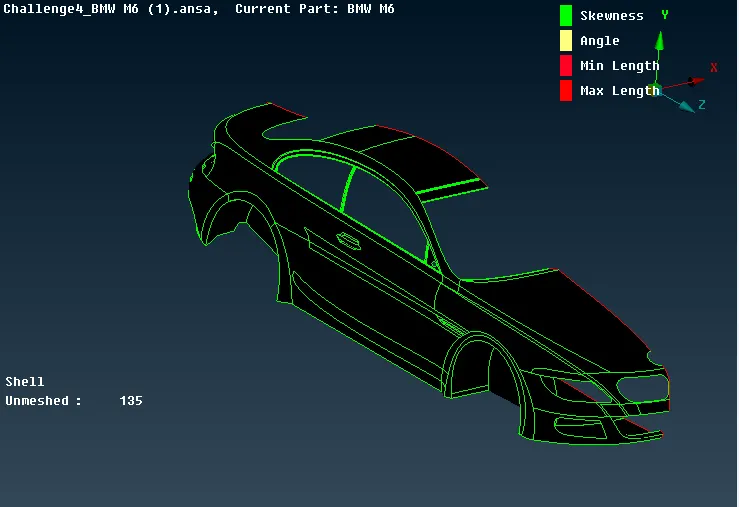
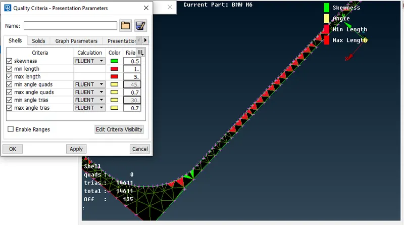
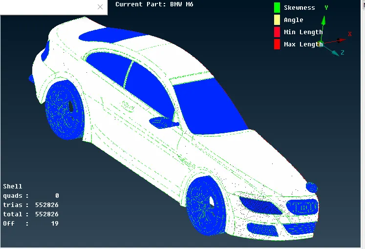
- It shows off-elements that fails quality criteria designated with various colors which can be solved using Reconstruct, Move, Smooth and Split Options.
C) Symmetry:
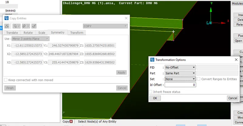
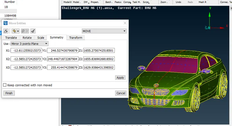
- After performing Surface Mesh to half of the car geometry, next is mirroring the geometry using the Transform> Copy > Entity > Symmetry > Mirror three-point axis> Apply (Note: Deselect Logo)
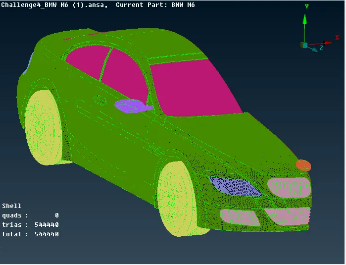
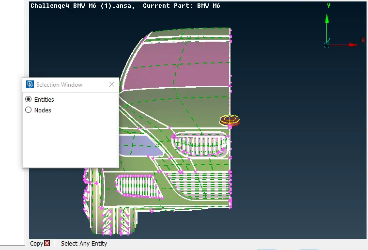
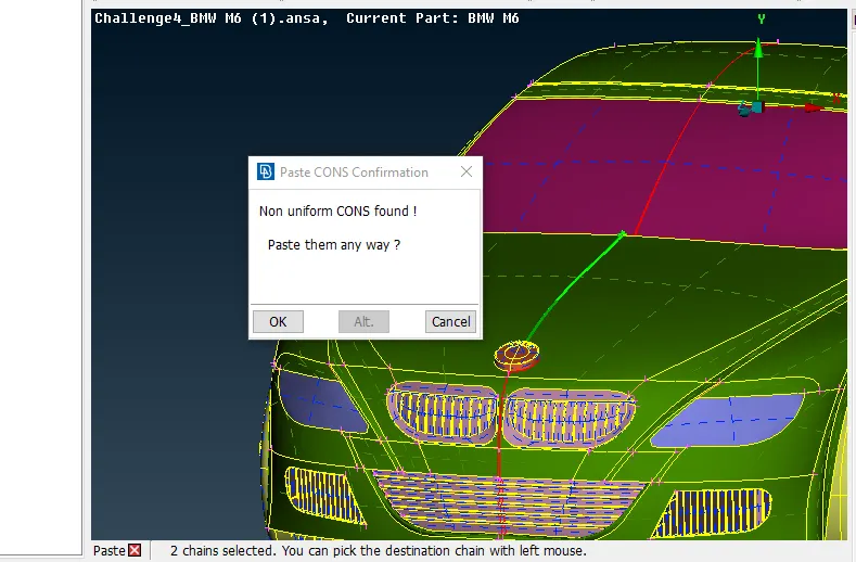
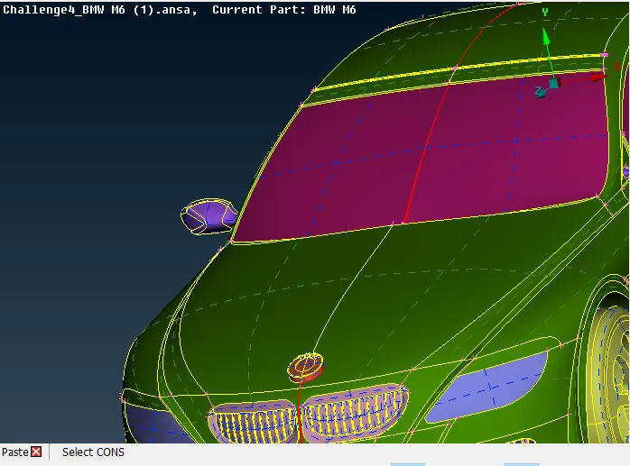
- The single cons identified over the car geometry are converted to double cons using the PASTE option throughout the entire car geometry.
- Once the symmetry operations are done, Next is to check the whole Geometry using Geometry> Check to verify single cons and other associated errors.
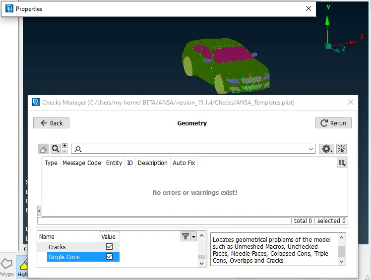
d) Creation of Wind Tunnel & Surface Meshing:
- Under this, the predecessor is the creation of a wind tunnel using:
- 1. Points
- 2. Curves
- 3. New face creation
- 4. Assigning different PIDs
- Points are created based on X(=1306mm) which is the distance of whole length of car in side view using Relative Option under Points.
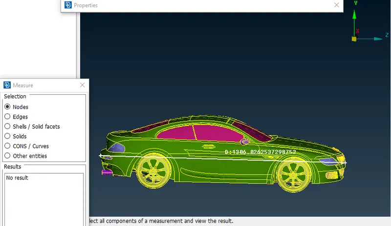
- Then the points are connected using Create Curves Option.
- Base surface is created at a distance of 750mm using relative point option extracted from bottom of the car.
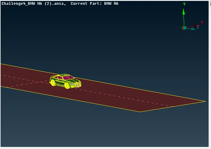
- Top Surface is created at a distance of 5X
- Front and Back Surface created a distance of 4x from the bottom reference point.
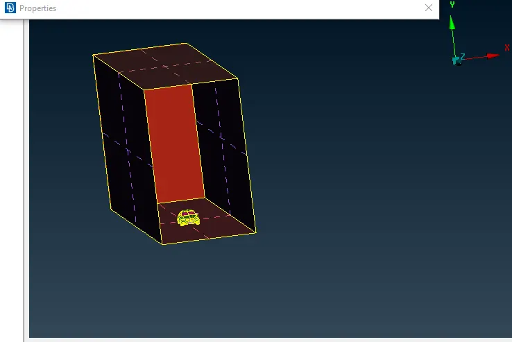
- Assign PIDs to all surfaces individually to perform surface meshing
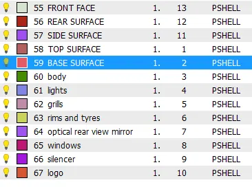
- Top surface is meshed with 100mm ( QC: 80 &120) & Bottom surface with 20mm (QC: 15&25) as target length as fine mesh is not needed all over the wind tunnel.
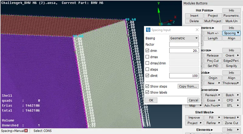
- Once the top and bottom surface mesh is done, next is the front, rear and lateral surfaces which is meshed using Spacing > Geometric > factor 1.1; dmin: 20 & dlimit :100
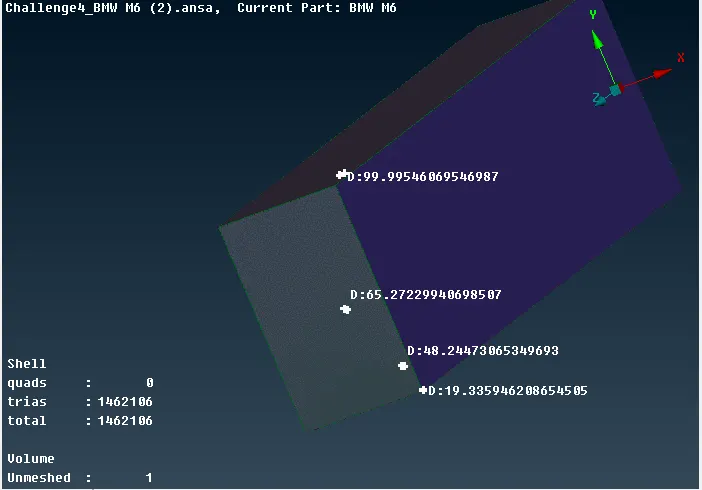
- The variable fine and coarse mesh of wind tunnel is observed using Measure > Node.
D) Volumetric Mesh:
- Once the surface mesh is done, the geometry is taken to the V.mesh mode to perform volumetric mesh
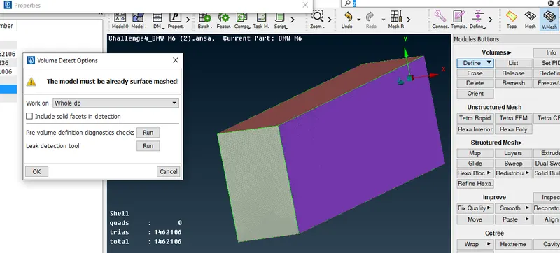
- the First step is to detect the volumes using Volumes> Define>Auto Detect > Ok
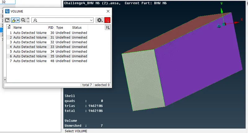
- It will auto-detect the unmeshed volumes. Here it is 7 unmeshed volumes
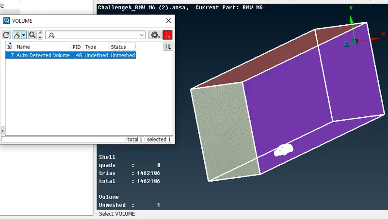
- On picking each entry, it shows the unmeshed volumes individually.
- The unwanted detected volumes are deleted and our volume of interest is chosen to perform our necessary task. (the volume between Car and Wind tunnel)
Result:
Thus the Whole operation starting from geometrical clean-up to Volumetric mesh is performed without any errors step by step to the car geometry and wind tunnel.
Please find the google drive link for geometry file: https://drive.google.com/file/d/1eeM2hnJJhZCkApEp5PQnFjkZSB0OBUMy/view?usp=sharing