Week 3 Challenge : CFD meshing on Turbocharger
CFD meshing on Turbocharger
Aim:
1. To check for the geometrical errors to make appropriate volumes for the given model ( Turbo-charger).
2. To Create and assign PIDs. Also to Perform surface mesh with the given target lengths as per PIDs.
- Blade stage-1 = 1 mm
- Blade stage-2 = 1 mm
- Impeller = 2 mm
- Shaft rotor = 1 mm
- Turbo casing = 5 mm
- Compressor casing = 5 mm
- Inlet casing cover = 5 mm
3. To Perform Volumetric mesh for the required volumes as given.
Procedure:
1. Open the given Turbocharger Model
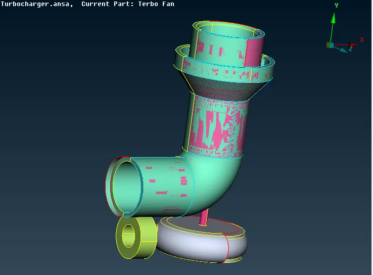
2. Delete the Surface Gleechings (overlaps) in PID MODE as part of performing geometrical clearance.
(Option: Delete)
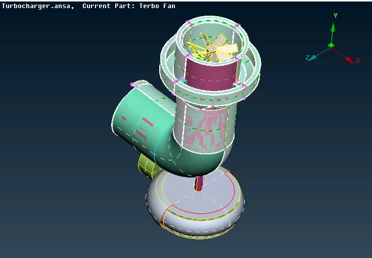
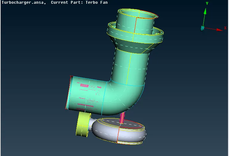
3. Deleting the unwanted Surfaces and filing the surface as required for geometry.
(Opt: Delete & New under faces using COONS)
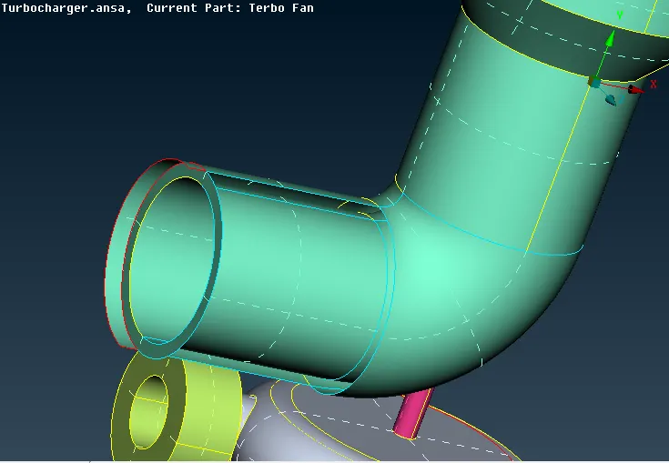
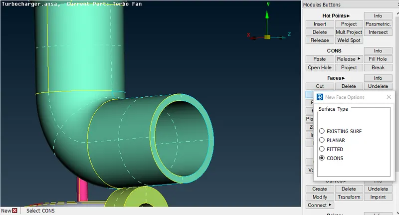
4. Creating new surface using creation of Hot Points, Project it on the cons and fill the surface
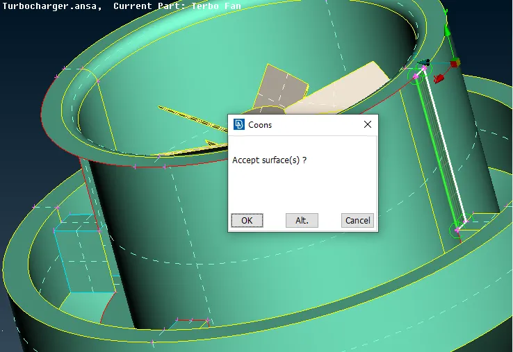
5.Solving Intersection of Surafces
(Opt : Intersect)
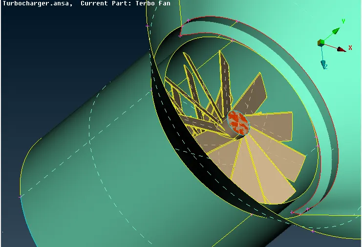
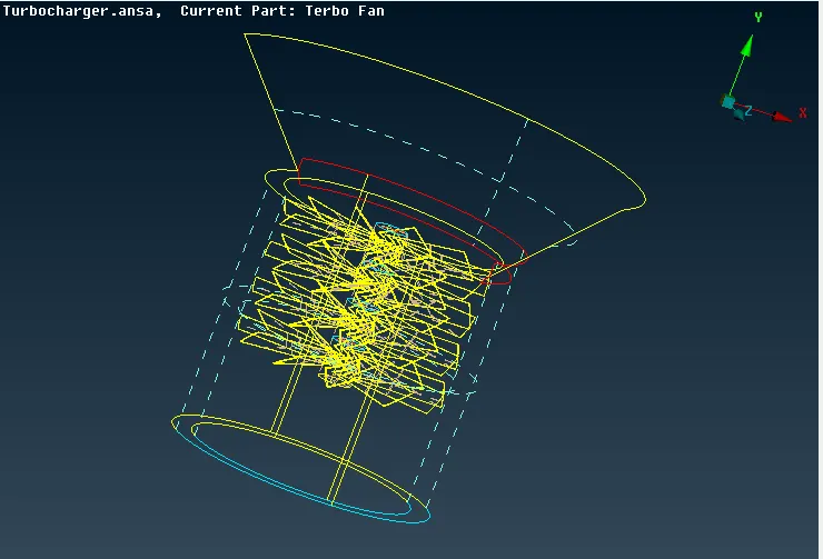
6.Grouping the surfaces to solve intersections
7. Creation of Hot Points and Creating the new surfaces on turbo casing.
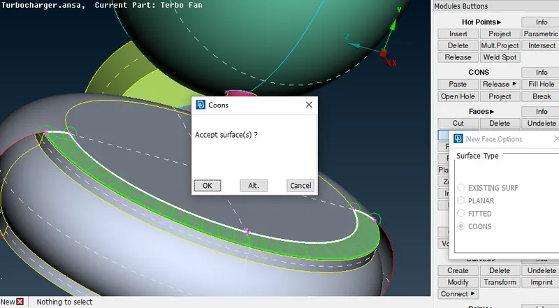
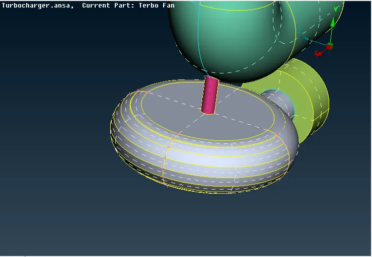
8. Verifying the triple cons using INOT
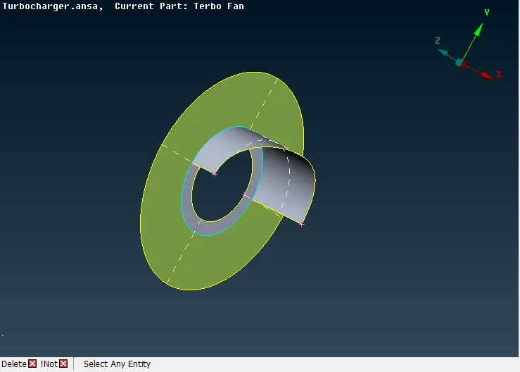
9. Delete the overlapped surfaces and fine tuning of surfaces using FINE option.
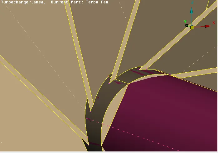
10. Creating a cut at open surfaces to close and isolate, then Apply Topo to solve single cons ( Pasting single cons to double cons using paste option)
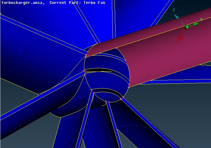
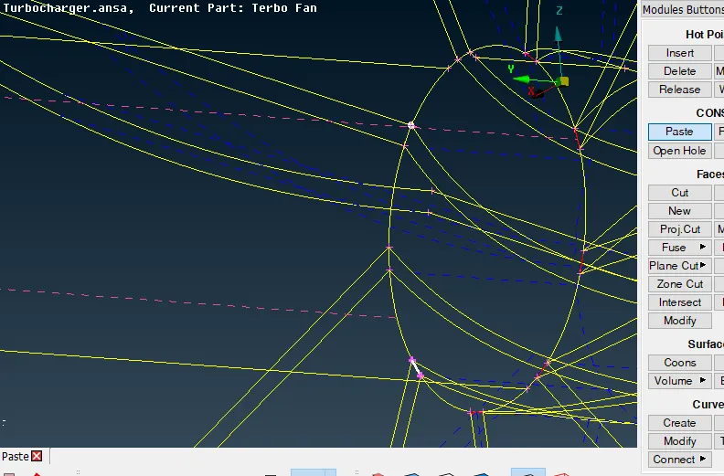
11. Solving the single cons: Using Release the cons and apply Topo to the cons
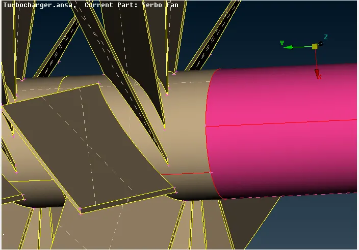
12. Geometry clearance: Execute check of blades, rotor shaft and impeller before surface meshing.
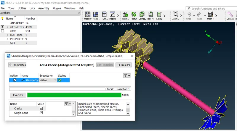
13. Whole Geometry Check of the model ( Triple cons are only observed which is valid rather invalid single cons, cracks are not observed )
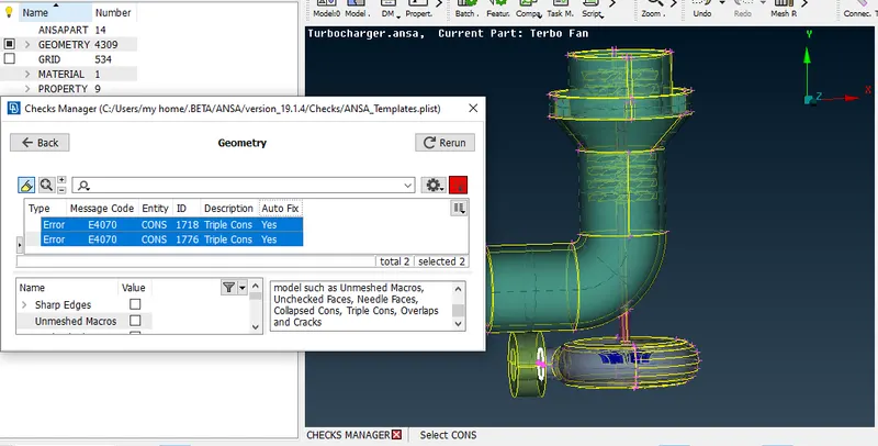
14. Compressor Casing top inlet Surface creation to make the model closed.
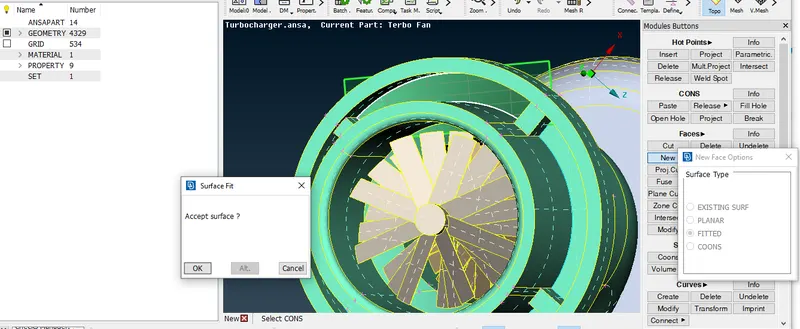
15. Solving Overlapped Surfaces, selecting the proper PID and deleting the over-rided surface
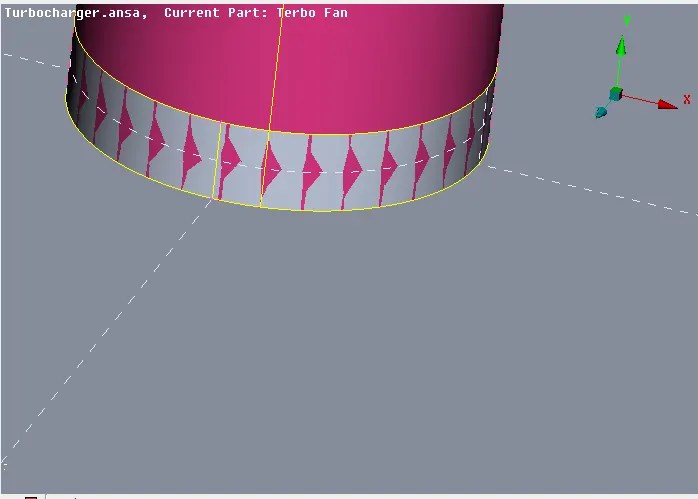
16. Assign PIDs & Inclusions of PIDs using Right click >Apply option
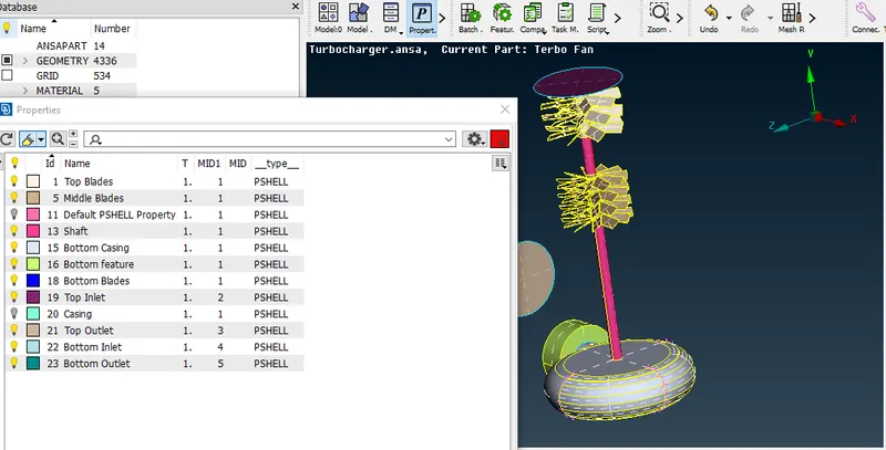
17. Once the geometrical clearance is fine and verified, Mesh using Spot mesh by assinging Perimeters ( Length , Macros ), Target length and Quality Criteria
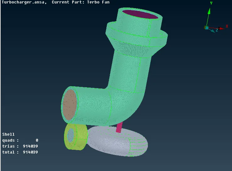
18. Blade Stages 1 & 2, Rotor Shaft Meshed ( Target Length : 1mm)
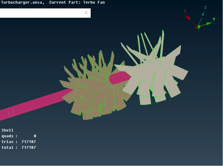
19. Compressor Casing, Turbo casing along with Inlet Outlet Sections meshed ( Target Length : 5mm)
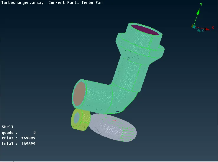
20. Impeller Meshed ( Target Length: 2mm ) & Variation due to shared circumference with rotor

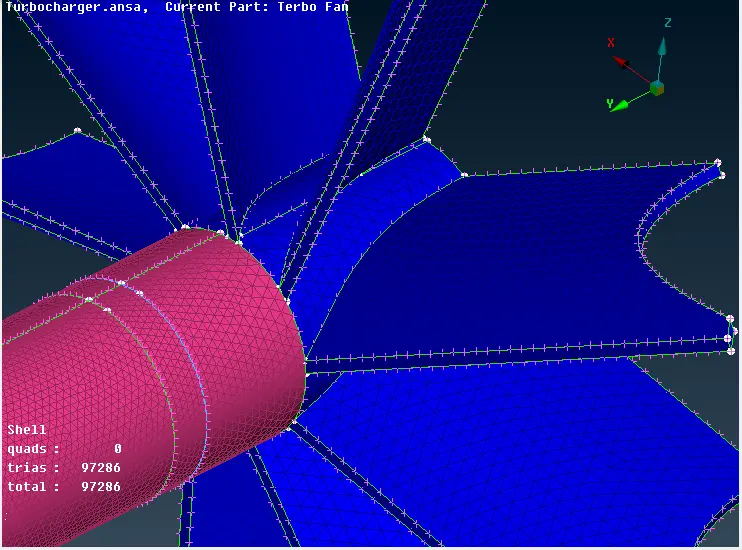
21. On checking, all the components has been meshed completely (Unmeshed: 0), Next part is Volumetic Mesh. Define the Auto Detect in VMESH mode to find unmeshed volumes.
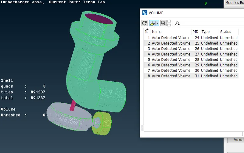
22. Delete the unwanted parent geometries ( thickness geometries) where the fluid flow is not associated. (before performing Volumetric mesh )
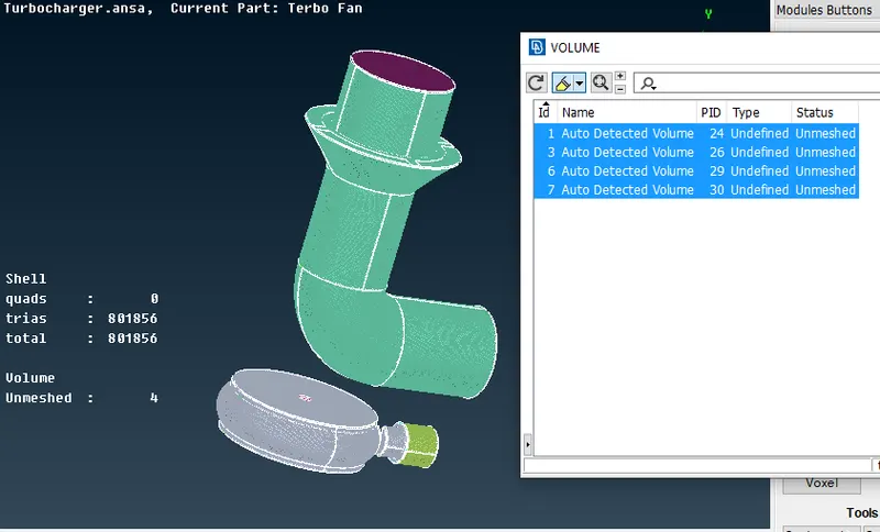
23. VMESH : Right click on the entry, select Remesh option to mesh with TETRA CFD
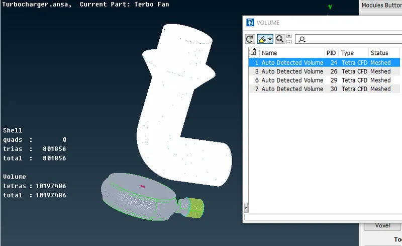
24. Once the VMESH is over, check the status.
In topo mode, as volumes seen merged with GEOMETRY and FE the gleechings are observed.
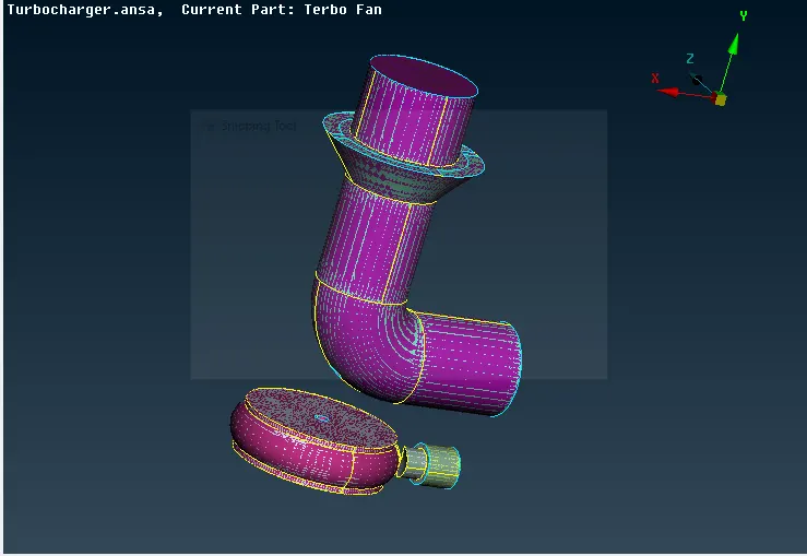
25. Disable geometry and FE mode to view volumes section alone, observe the meshes
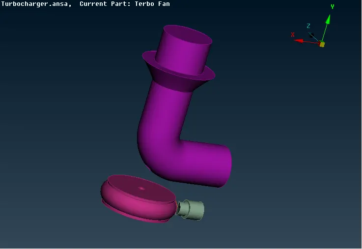
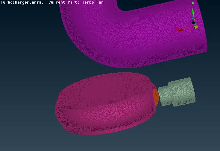
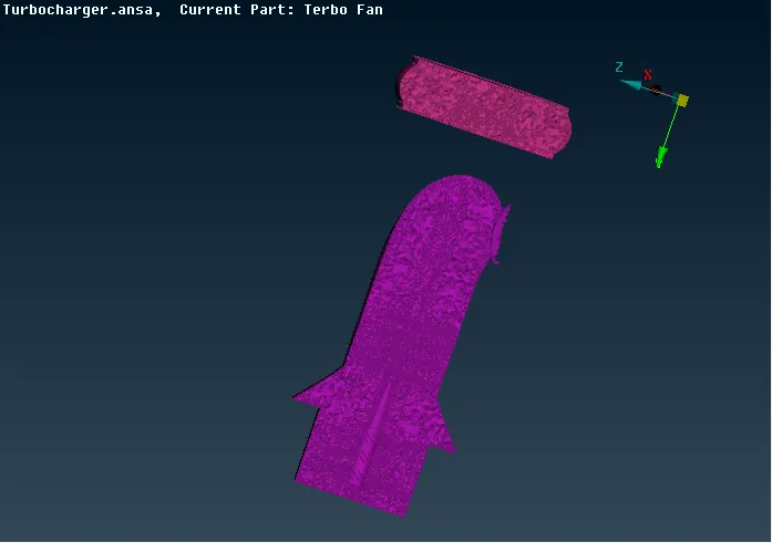
26. Make a cross section using NOT option to see the volumetric mesh elements and its variation in sizes throughout the model
Result :
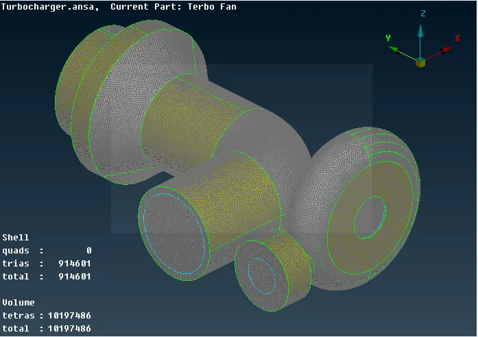
Hence the Surface mesh (Shell) with assigned target lengths and Volumetric (Solid) mesh are performed on the project titled CFD meshing on Turbocharger.
The elemental results are noted and enclosed in the below image.