Week 4 Challenge : CFD Meshing for BMW car
AIM/OBJECTIVE:
- For the given model, check and solve all geometrical errors on half portion and Assign appropriate PIDs.
- Perform meshing with the given Target length and element Quality criteria.
- After meshing the half model, Do symmetry to the other side.
GIVEN:
a. Challenge4_BMW M6.ansa file to be downloaded
b. Target lengths for the different parts of a model are as follow:
- Body - 3 mm
- Lights - 4 mm
- Grills - 1 mm
- Rims and Tyres - 2 mm
- Optical Rear view mirror - 2 mm
- Window - 2 mm
- Silencer - 3 mm
- Logo - 1 mm
BASIC STEPS TO BE FOLLOWED WHILE STARTING THE ANSA
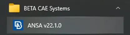
Click on the ANSA v22.1.0 in the Start Menu to open the ANSA software.
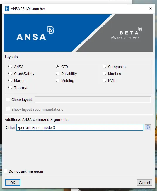
After clicking the ANSA v22.1.0 the above window pops up. In the above poped up window, select the CFD in Layouts.
In additional ANSA command arguments change the other to -performance_mode 3
Always remember not to click/tick on Dont ask me again. Finally click the OK button.
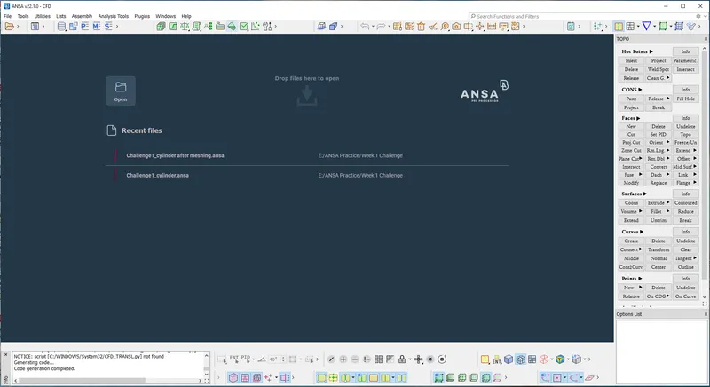
After opening the above window, right click on the top tab with icons and select the show labels and click apply to all
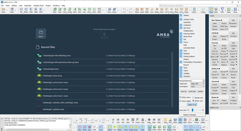
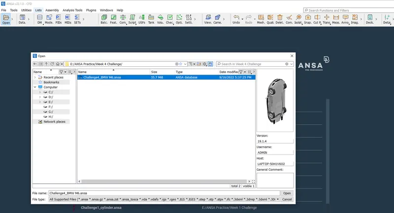
Open the downloaded Challenge4_BMW M6.ansa file as shown below
The above file will be opened in wireframe mode as shown below.
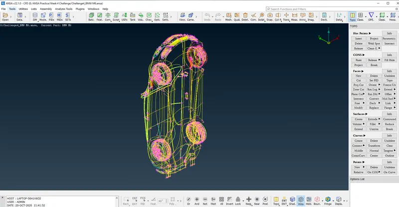
On opening the model you will see the following:
Single cons, Red cons or Double cons, Blue cons, Purple cons and hot points.
Turn on the shading mode by using the red encicled button as shown in the below figure.
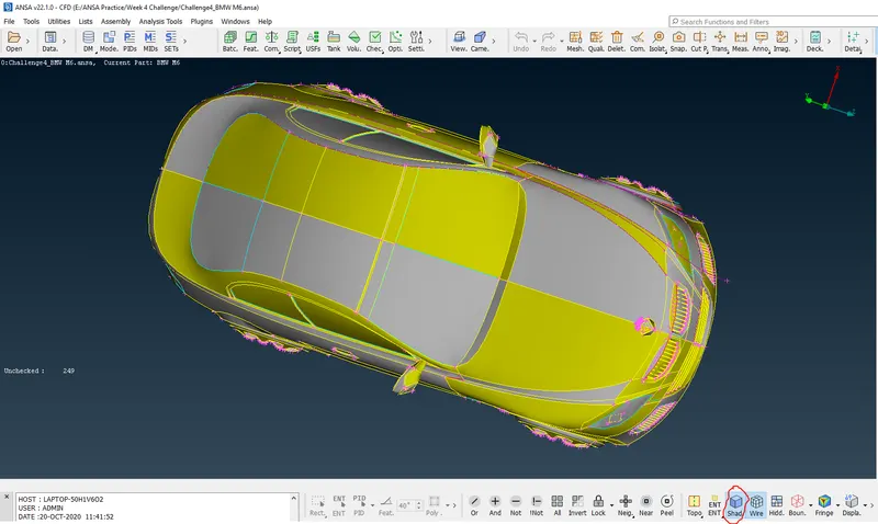
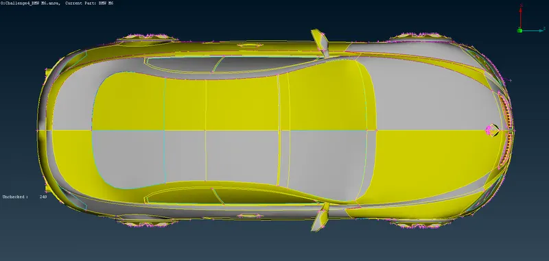
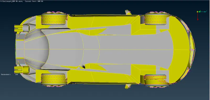
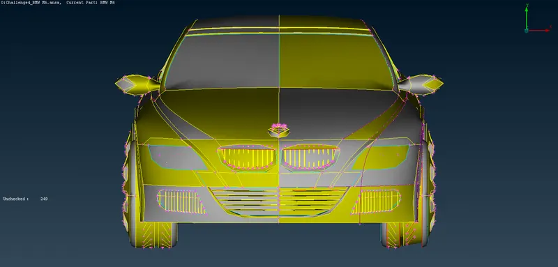
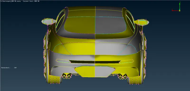
On carefully observing the model of the BMW car we understand that the model is symmetric in Nature when viewed from front and back. Hence we will delete the half part of the BMW half.
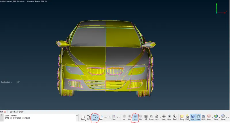
While deleting the half part of the model, it has been noted that BMW logo on the car is not symmetric and hence it was isolated before deleting the half part by using Not and PID encircled in red.
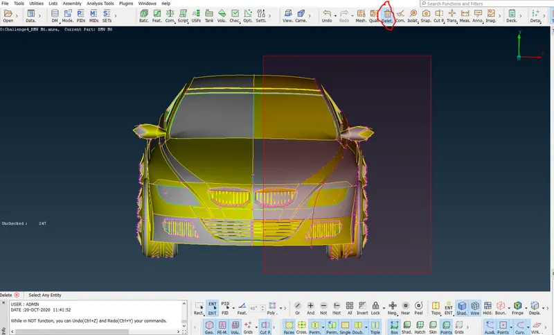
Then by using universal delete we make the selection box by dragging the left click on the mouse and press the middle click on the mouse. 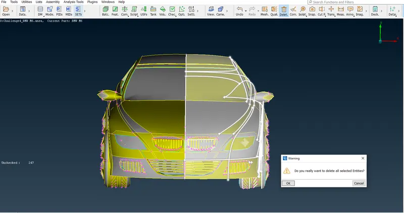
After middle click on the mouse a new window pops up confirming the selection to be deleted. On clicking the OK the half portion of the model gets deleted.
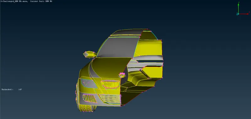
Now our strategy would be to work on the half portion the BMW model by removing the geometric and intersection errors, assign the PIDs and do the meshing.
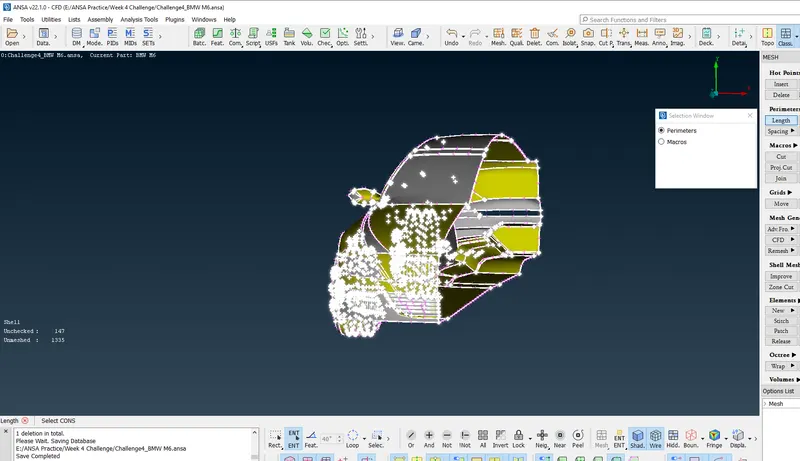
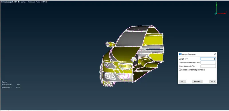
We tune in the resolution as shown above.
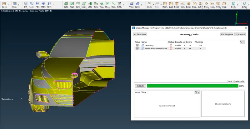
We do the Geometry Checks using Checks Manager and found the geometry and intersection errors.
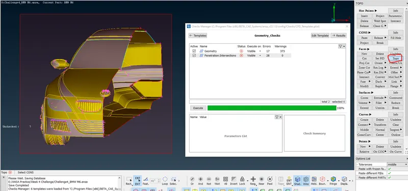
Next thing we do the TOPO by using TOPO encircled in RED.
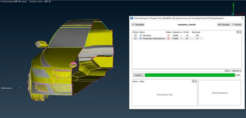
After TOPO we again execute the geometry check by using the Checks Manager and found that some erors are rectified using TOPO.
Now we will start reolving the errors, first we attempt to resolve the errors in lower central grill [Grill 1].
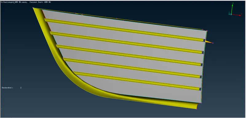
Grill 1 view from outside after isolating using Not option
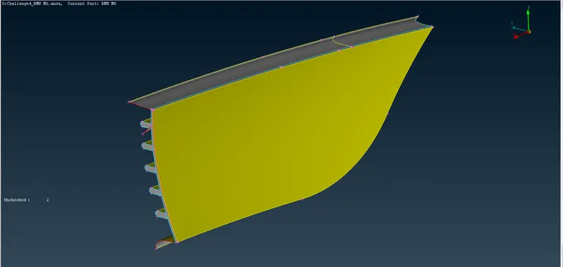
Grill 1 view from inside after isolating using Not option
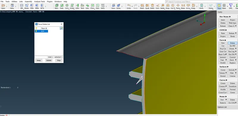
We delete this face as this is not required.
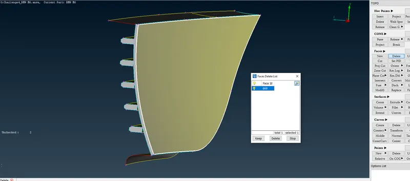
We delete this face as this is not required, this face is one factor which can create an extra volume which is not required.
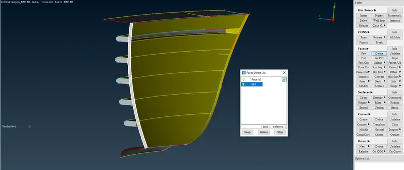
We delete this face as this is not required, this face is one factor which can create an extra volume which is not required.
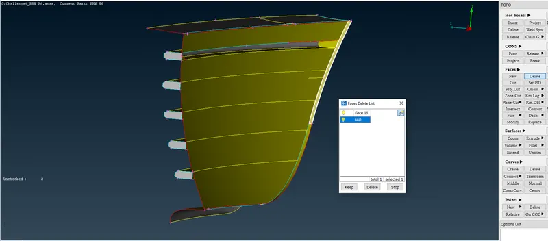
We delete this face as this is not required, this face is one factor which can create an extra volume which is not required.
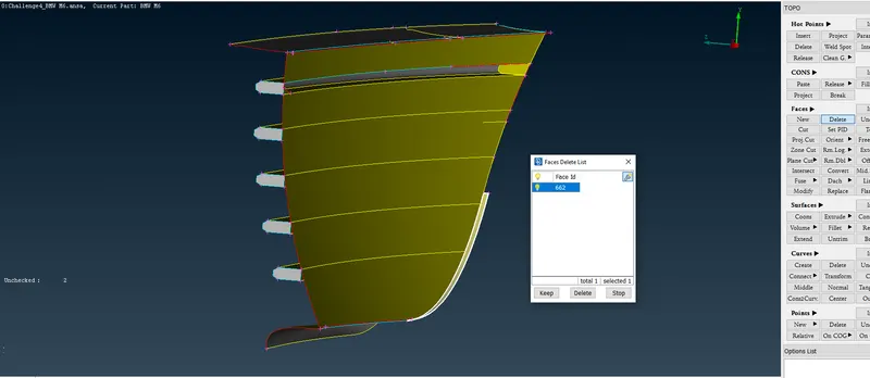
We delete this face as this is not required, this face is one factor which can create an extra volume which is not required.
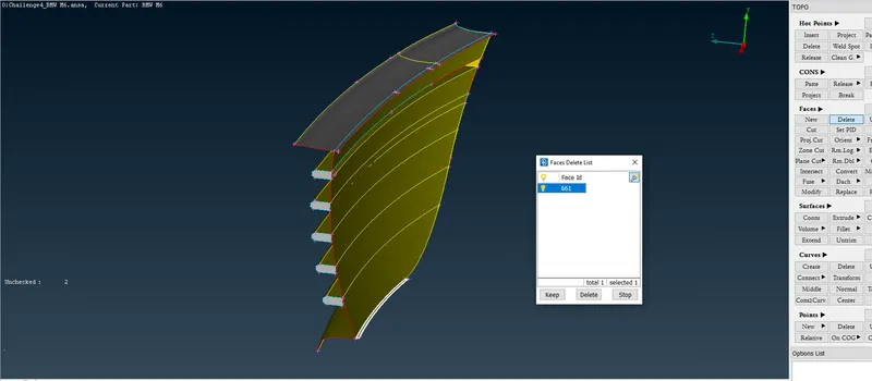
We delete this face as this is not required, this face is one factor which can create an extra volume which is not required.

We delete this face as this is not required, this face is one factor which can create an extra volume which is not required.
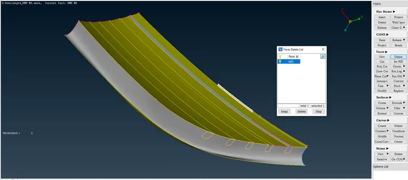
We delete this face as this is not required, this face is one factor which can create an extra volume which is not required.
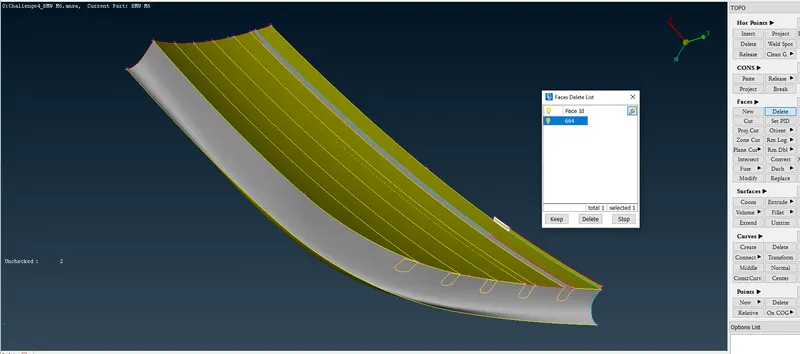
We delete this face as this is not required, this face is one factor which can create an extra volume which is not required.
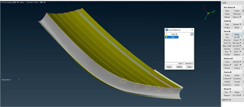
We delete this face as this is not required, this face is one factor which can create an extra volume which is not required.
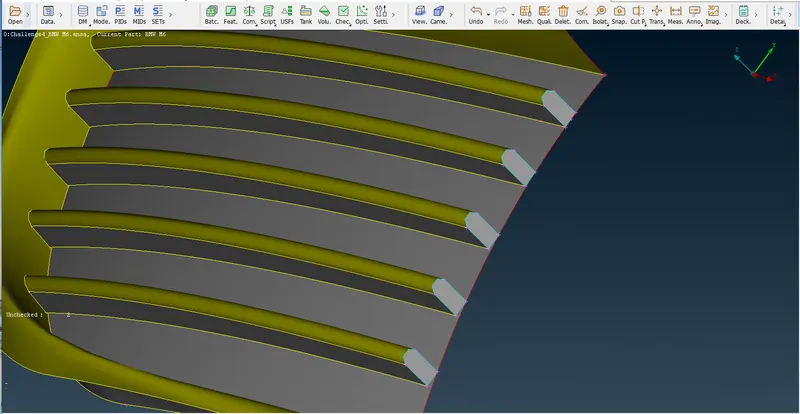
Fins in the Grill 1 are creating the extra volume which is not desired. Also the fins are not properly alligned with the base.
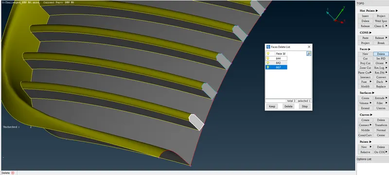
We delete this face as this is not required.
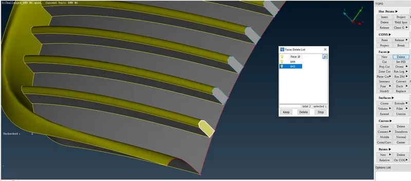
We delete this face as this is not required.
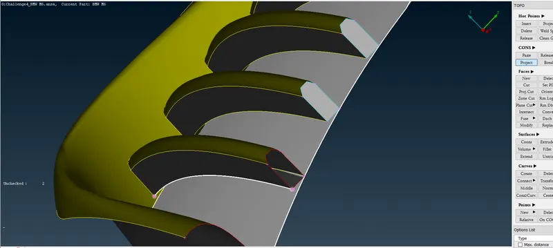
We project the cons on the fin over the base surface selected. This is done by using the Project under CONS in TOPO
Click Project, select the cons press the middle mouse / scroll button, select the surface on which it has to be projected and then press the middle mouse / scroll button.
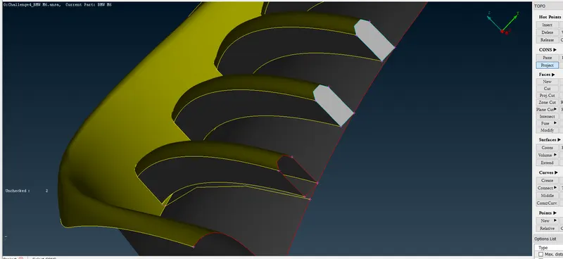
The cons has been projected over the desired surface.
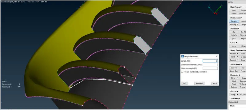
The resolution of the projected curves or cons has been set using Length under Perimeters in MESH.
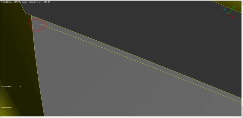
We see that the projected curve / cons is not intersecting the curve as shown in the red highlighted.
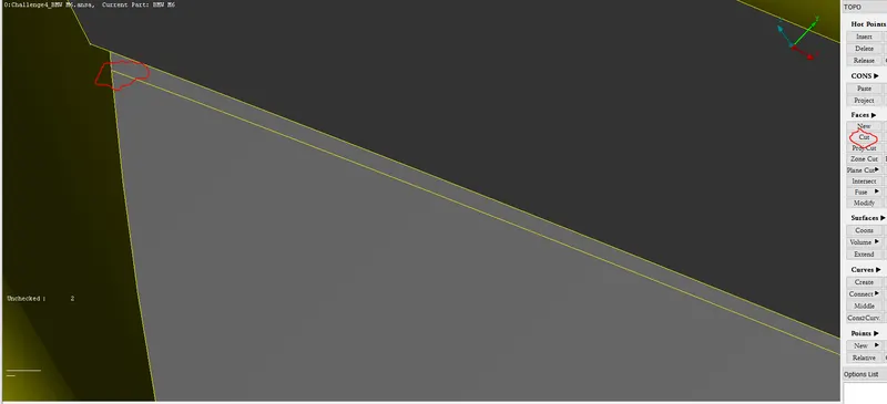
Using Cut under Faces in TOPO we intersect the required curve.
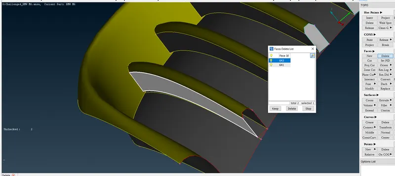
We delete this face as this not required.
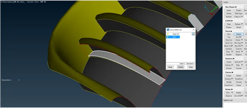
We delete this face as this is not required.
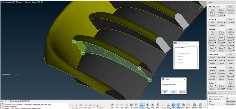
We create this New face by Using New under Faces in TOPO.
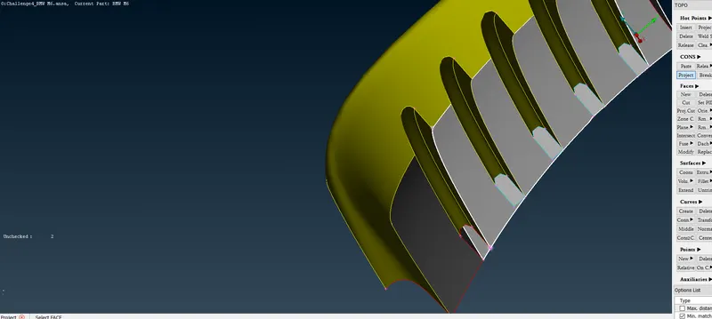
We are projecting the cons of the other side of the fin over thbase surface as shown above.
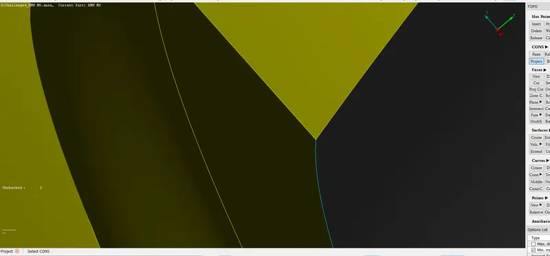
The project cons is intersecting with the desired curve.
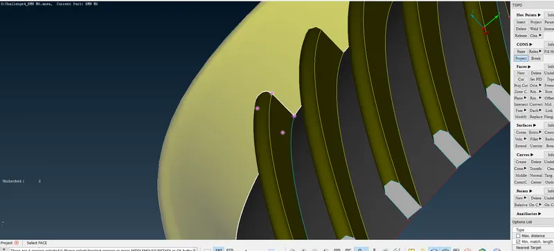
Now we are projecting the perimeter of the fin over the selected surface.
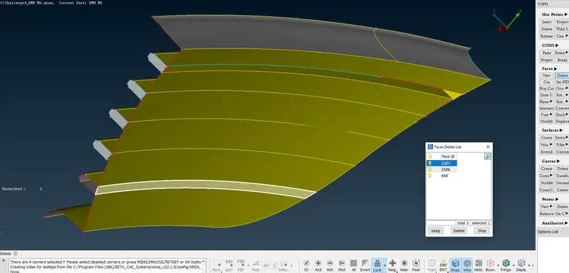
We are deleting the selected surface as this is not required.
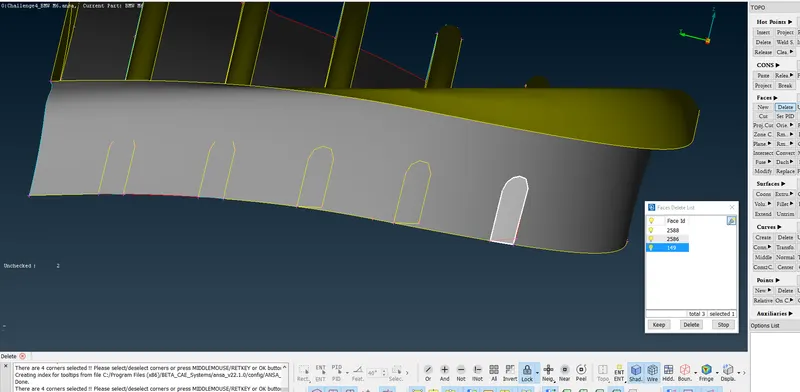
We are deleting this face as this is not required.
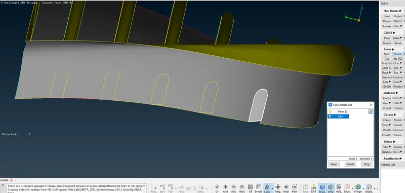
We are deleting this face as this is not required.
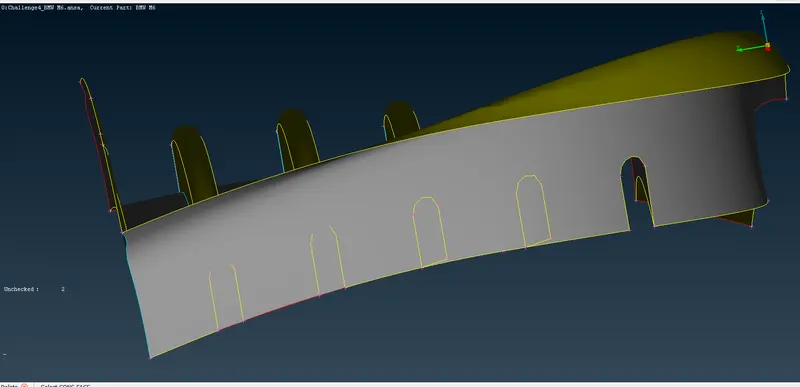
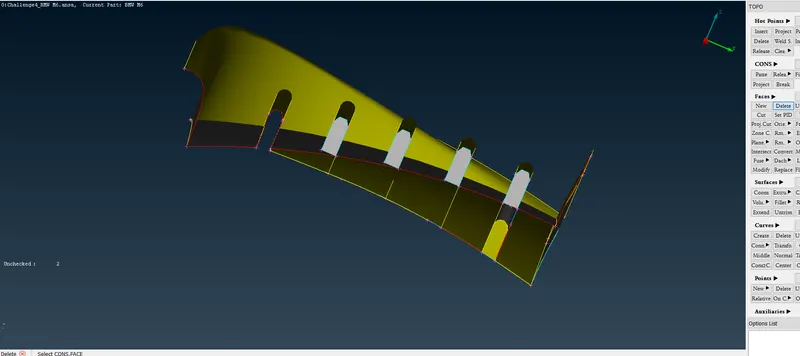
This how the fins are desired to look like which can create a single volume only.
We will follow the similar process for the remaining four fins.
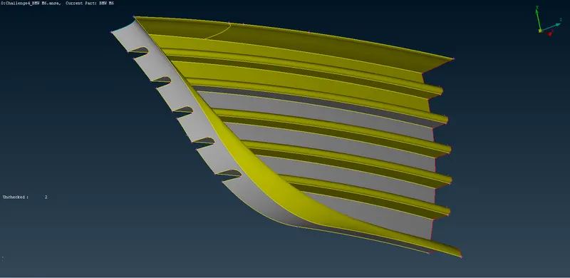
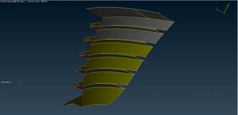
This is how the lower central grill [Grill 1] will look like after geometry clean up.
Now we attempt to do the geometry clean up of lower side grill [Grill 2].
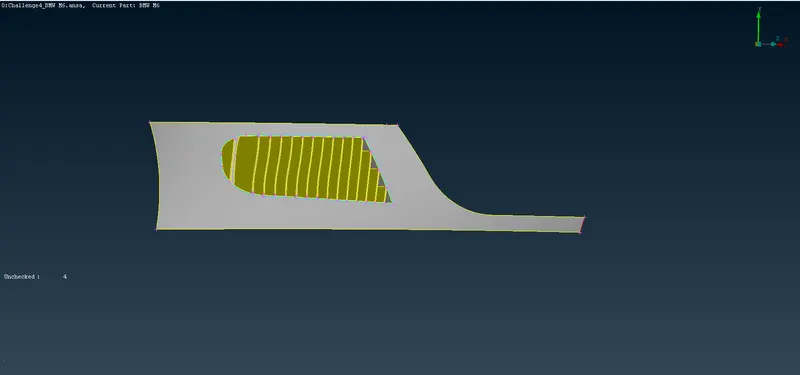
Outside view of Grill 2 after isolating it from the entire car using Not option.
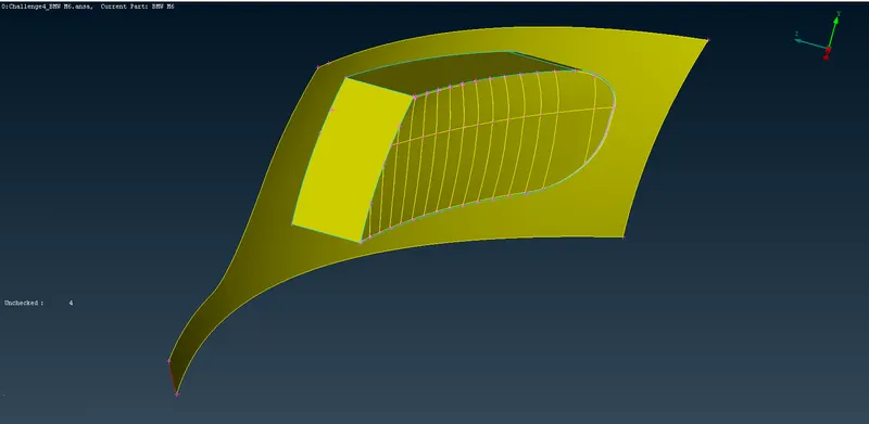
Inside view of Grill 2 after isolating it from the entire car using Not option.
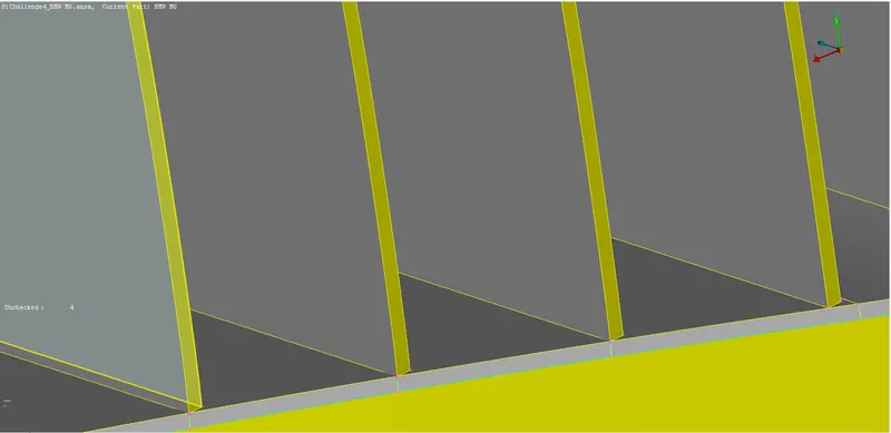
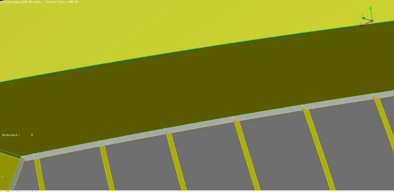
These are the errors in the Grill 2.
We are attempting to eliminate this error by creating a surface by using cut option so that we can delete the undesired portion of the Grill 2 from inside.
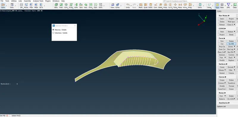
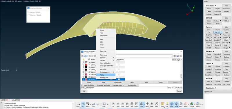
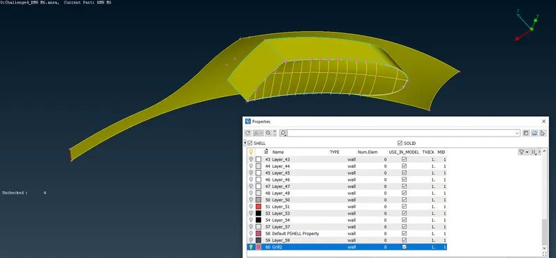
We assign a new PID Grill2 using Set PID under Faces in TOPO
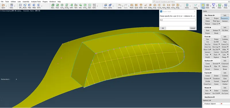
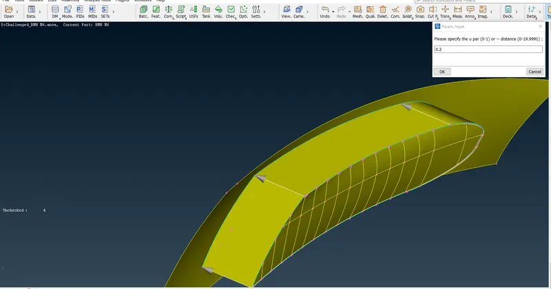
We are creating the hot points using Parametric under Hot Points in TOPO. On clicking the Parametric a New window pops up where we have the distance at which we want the new hot points to be placed. We enter the distance and click the cons on which the hot points are to be created and press OK.
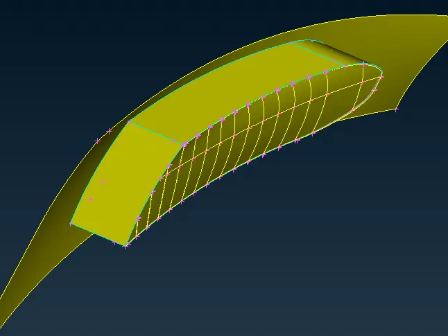
In the above image we can see the Hot Points are created.
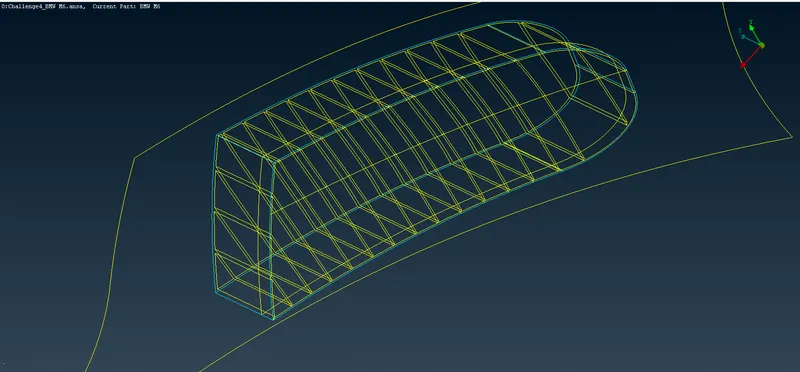
We have created a cut using Cut option under Faces in TOPO
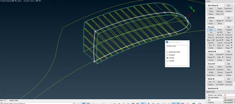
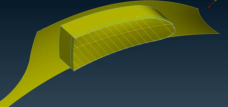
We are creating a New face using New option under Faces in TOPO as shown in above image.
A New Face is created.
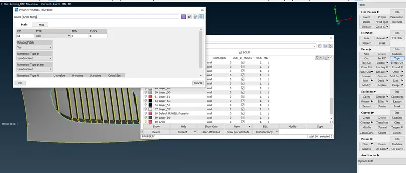
Now we assign a PID named Grill2 temp to the newly created face.
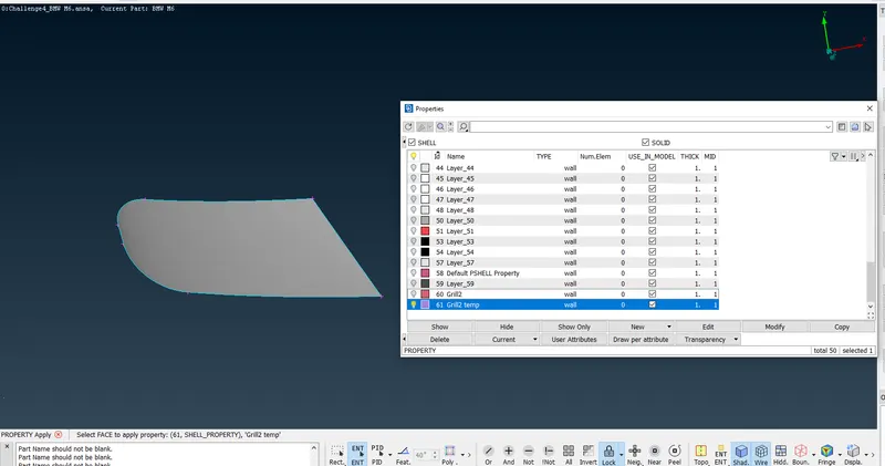
A new PID has been assigned.
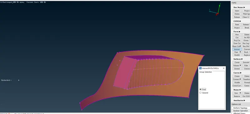
Now we do the intersect using Intersect under Faces in TOPO, usng PID region we select the first PID as selected in the above image.
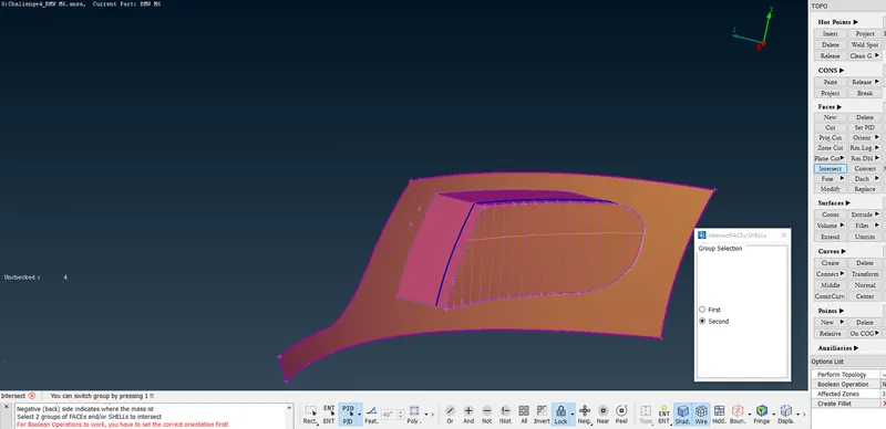
We select the second PID as shown above and do the middle click of the mouse.
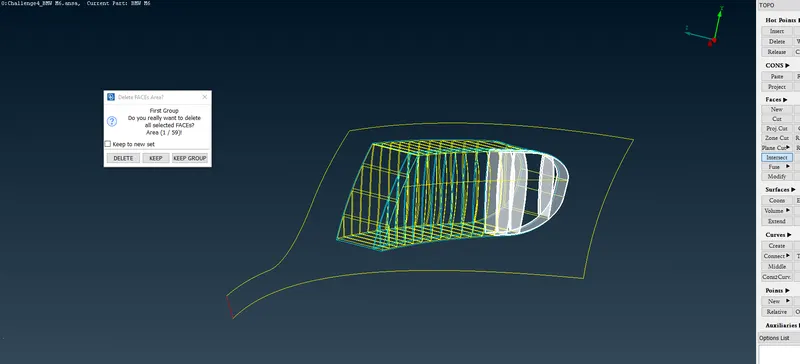
We delete this face as this is not required.
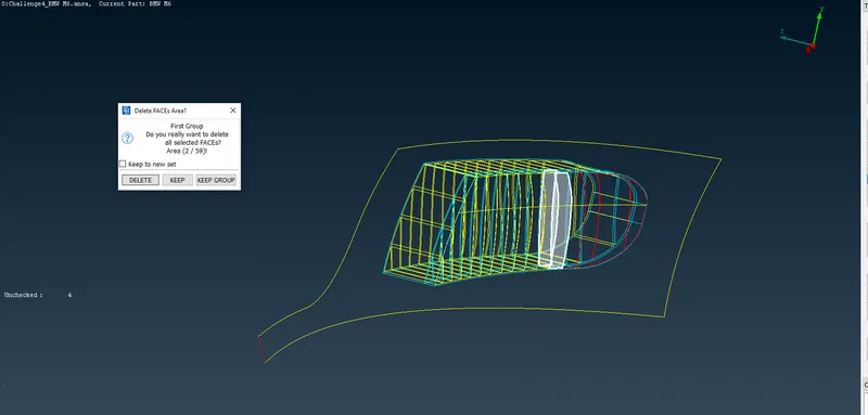
We delete this face as this is not required.
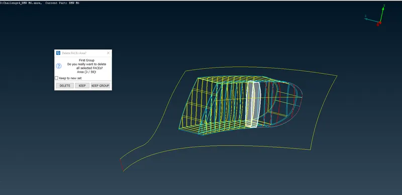
We delete this face as this is not required.
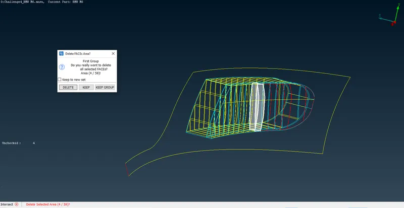
We delete this face as this is not required.
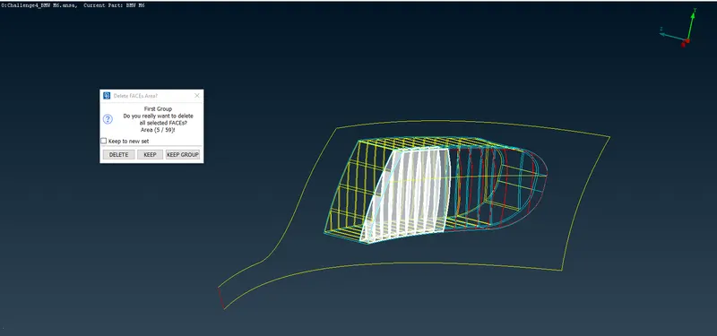
We delete this face as this is not required.
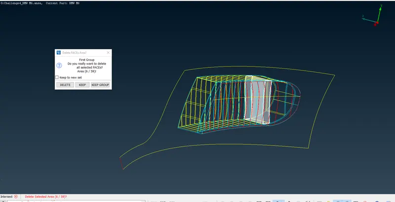
We keep this face as this is required.
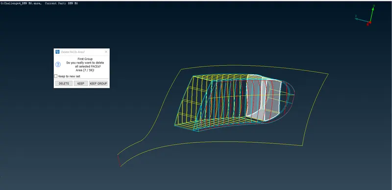
We keep this face as this is required.
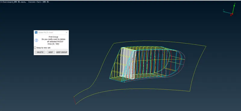
We keep this face as this is required.
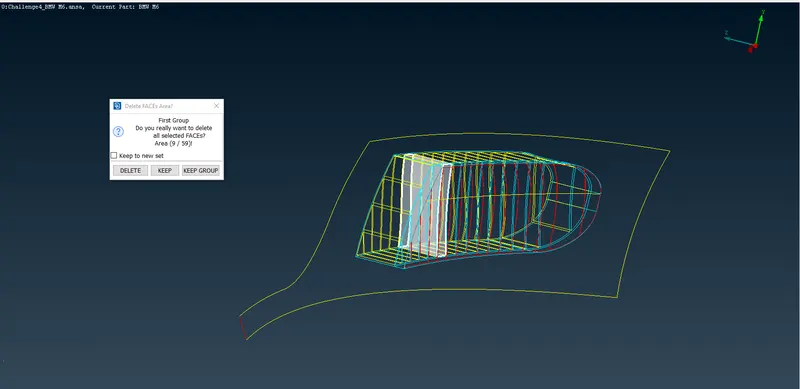
We keep this facee as this is required.
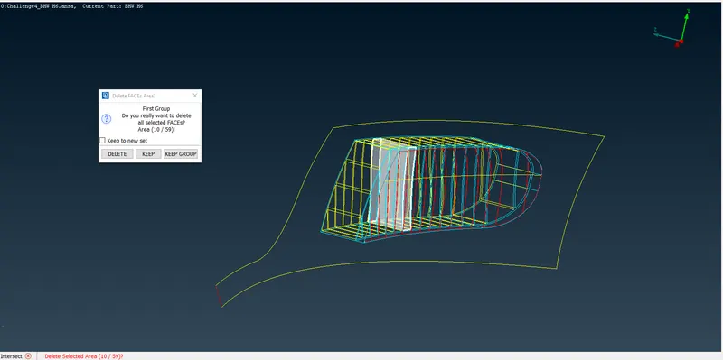
We eep this face as this is required.
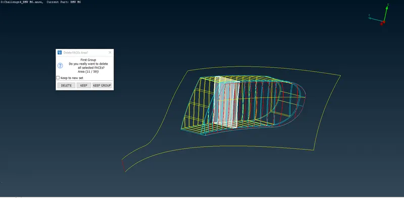
We keep this face as this is required.
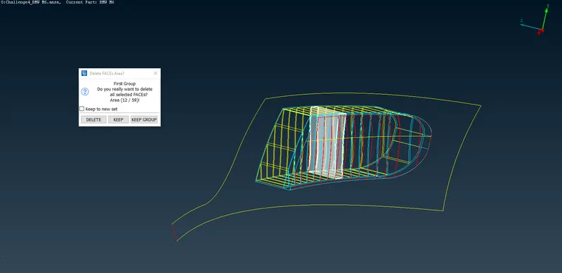
We keep this face as this is required
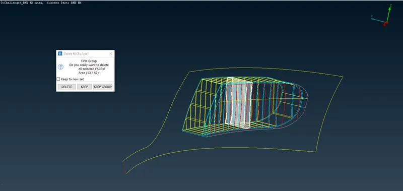
We keep this face as this is required.
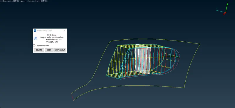
We keep this face as this is required.
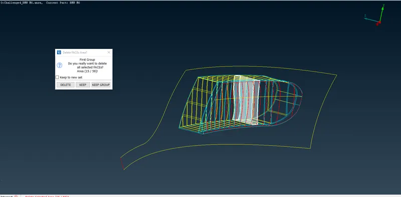
We keep this face as this is required.
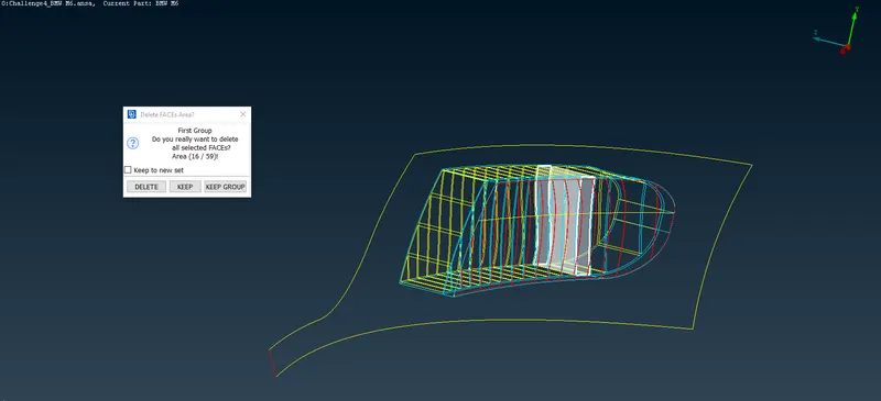
We keep this face as this is required.
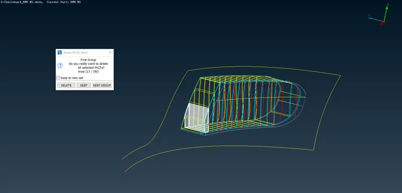
We keep this face as this is required.
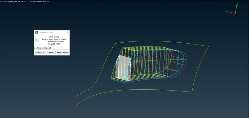
We keep this face as this is required.
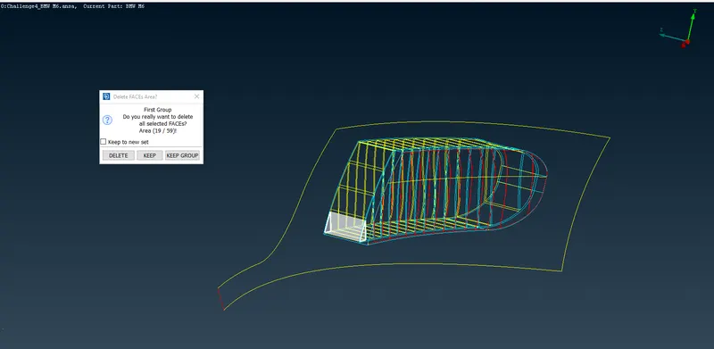
We keep this face as this is required.
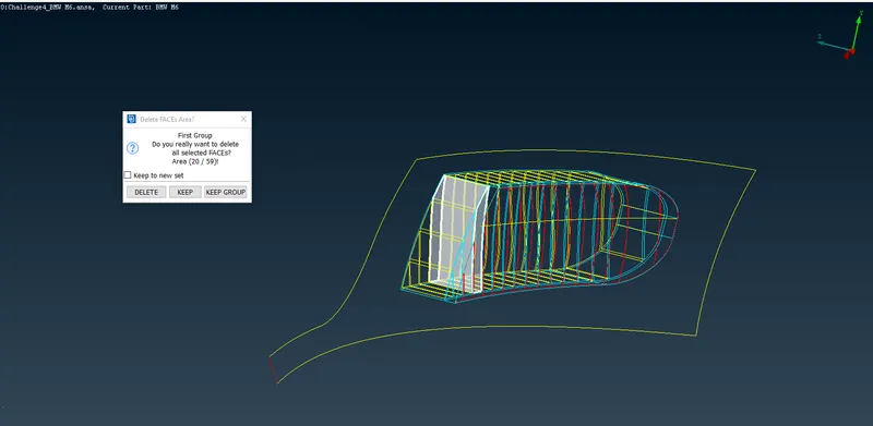
We keep this face as this is required.
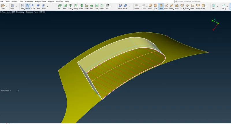
We are deleting this face using universal delete as this is not required.
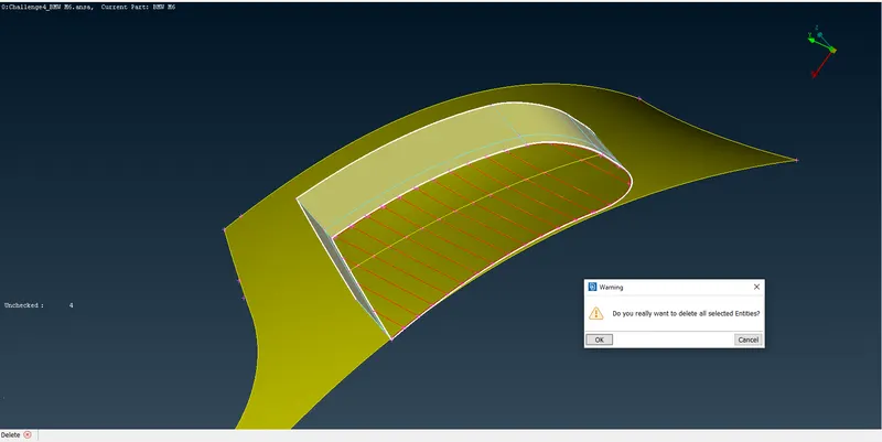
After deleting the above surface we find that there was one more layer of the surface beneath.
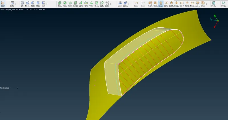
We select the undesired surface delete byclicking on them.
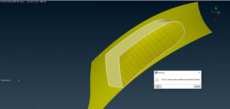
We delete the selected surface using the universal delete option.
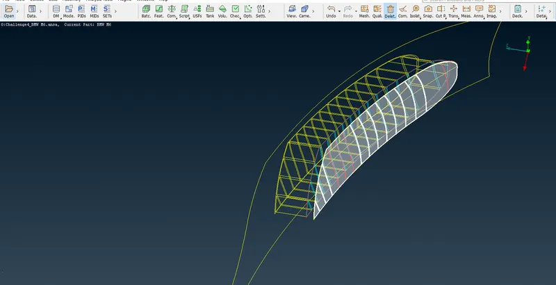
We select the undesired portion
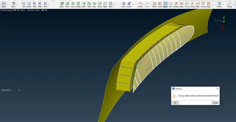
We delete the undesired portion using universal delete option.
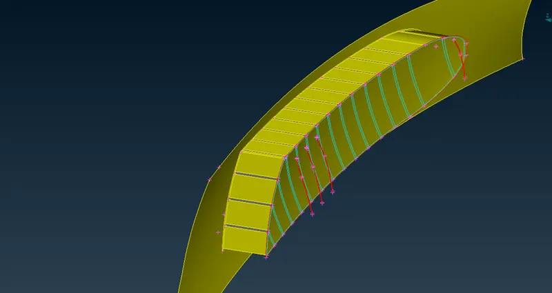
After deleting the undesired portion, there were few red cons present.
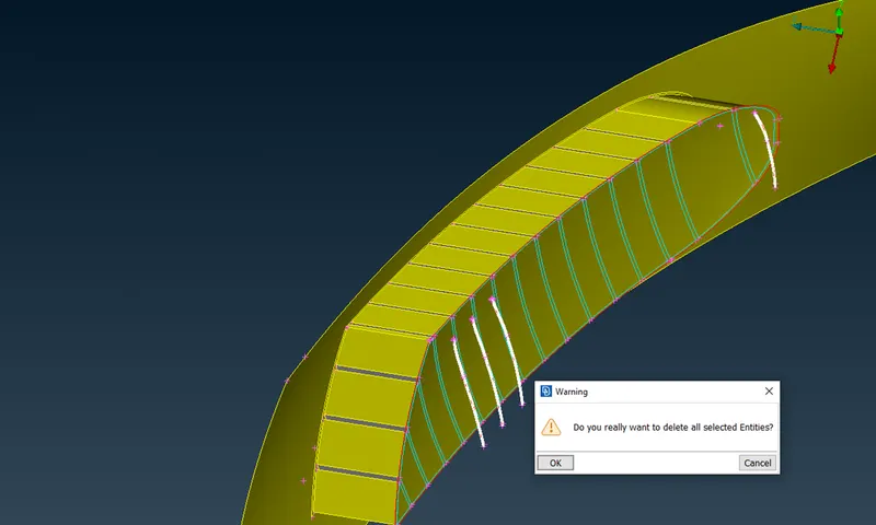
We select four of the red cons as shown in the above figure and delete them using universal delete option.
Then there was one red cons left, to delete this we inactivate the double cons and triple cons then we delete the red con face using the delete option under Faces in TOPO.
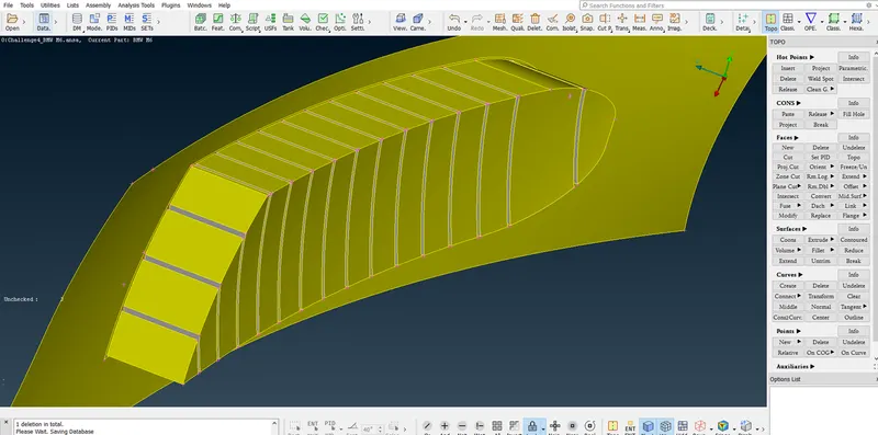
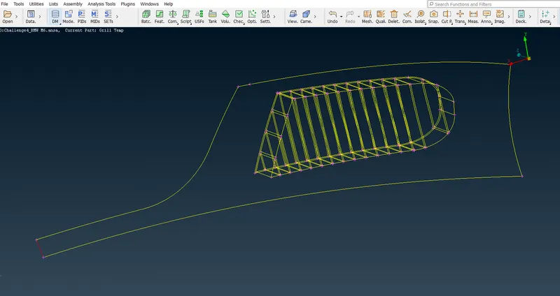
The finalised Grill2 after geometry cleanup
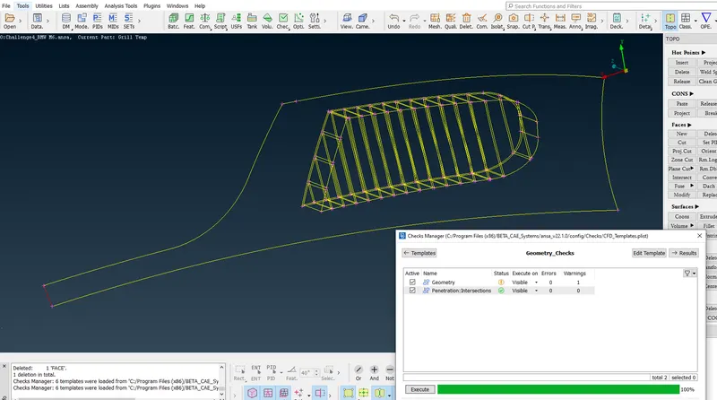
We did the geometry check using Checks Manager and found 1 warning
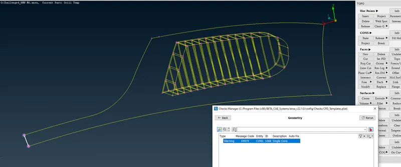
This warning and it is ok to proceed.
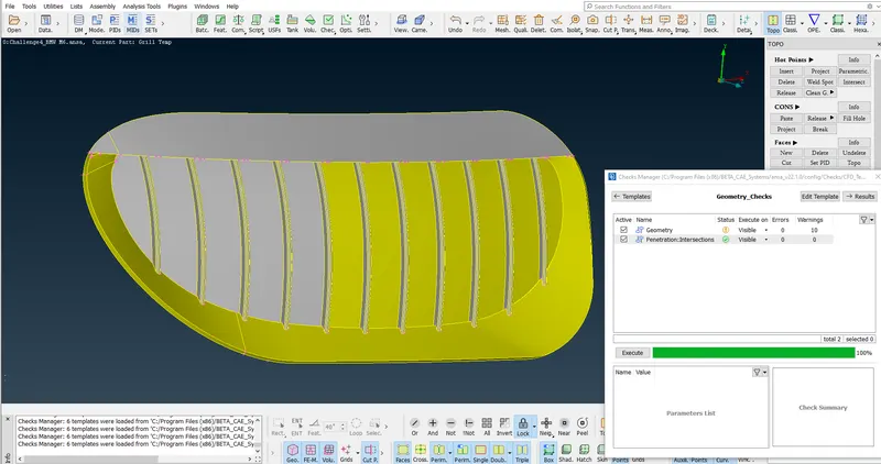
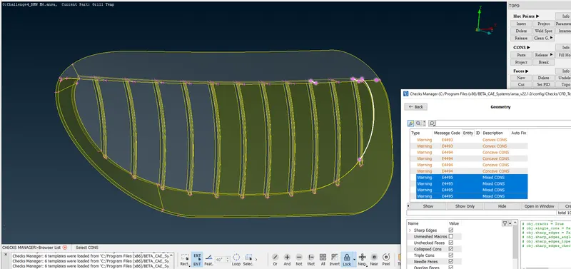
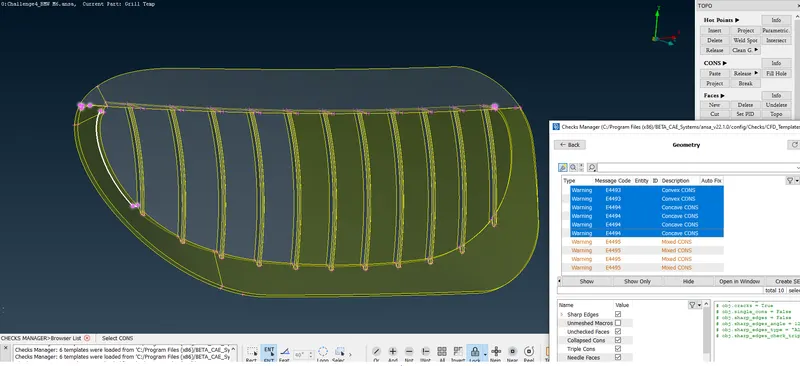
Now we attempt to work on the errors for Upper central grill [Grill3]
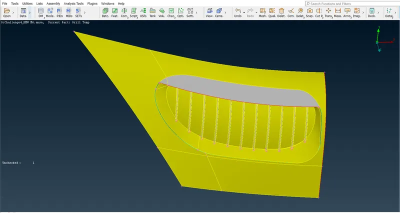
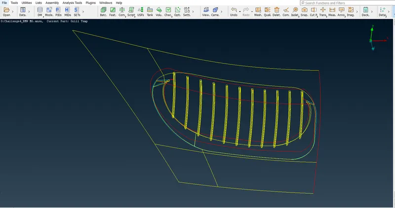
Grill3 in wireframe mode
First we try to reduce the blue cons from front of the grill.
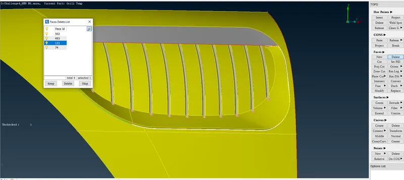
We delete this face as this is not required.
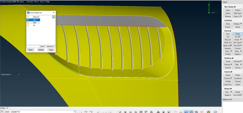
We delete this face as this is not required.
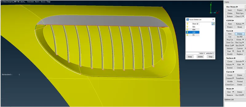
We delete this face as this not required.
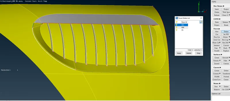
We delete this face as this is not required.
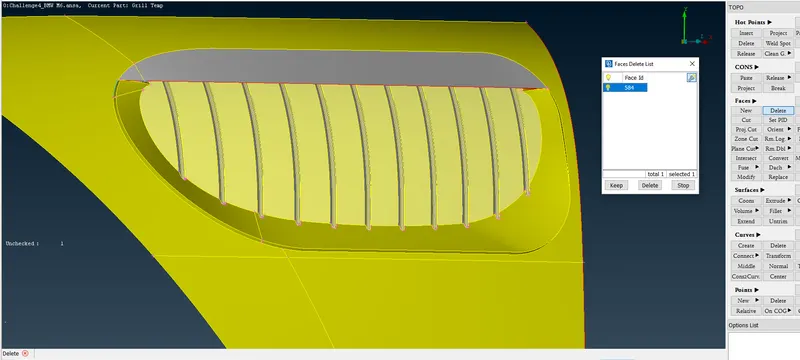
We delete this face as this is not required.
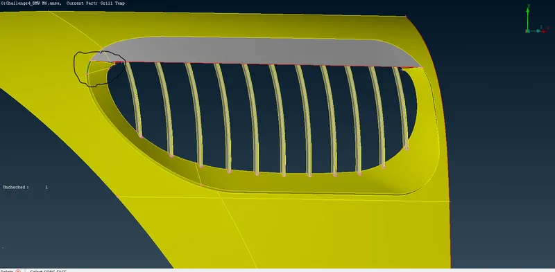
In the above image we see that blue cons are gone except for black encircled portion.
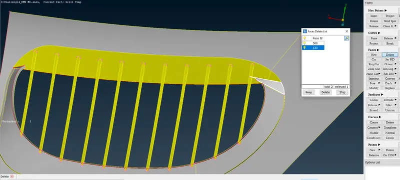
We delete this face as this is not required.
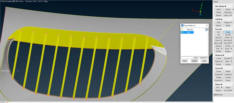
We delete this face as this is not required.
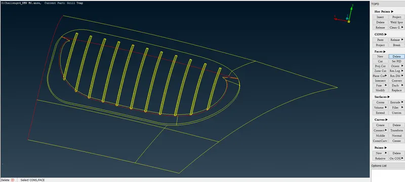
In the above image we see that no triple conss or blue cons are present
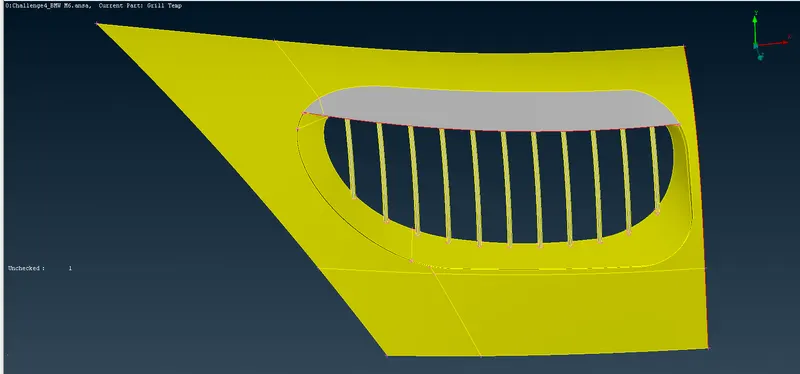
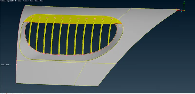
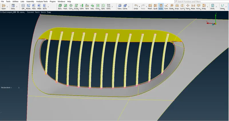
Using universal delete we deleting the selected surfaces.
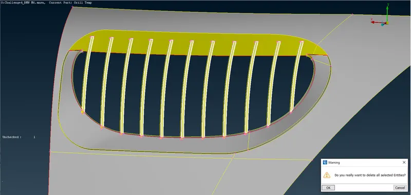
On middle click of the mouse a new window pops asking for confirmation of delete. Now the grills are open.
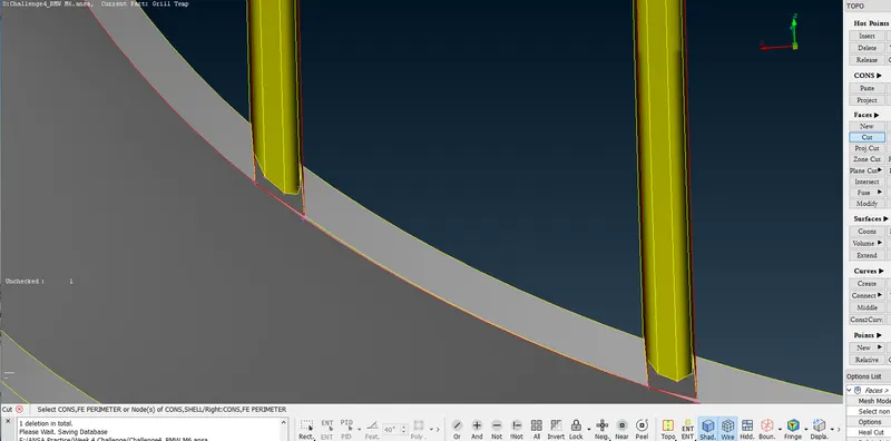
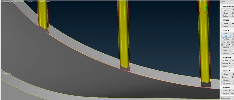
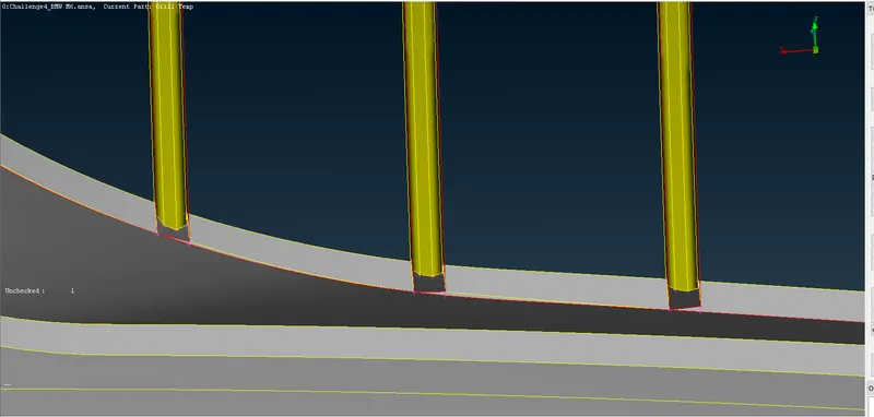
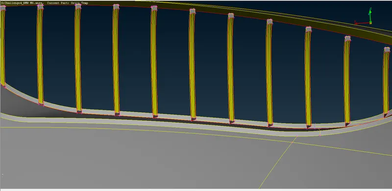
On the base of grill we are creating a cut as shown in above figures.
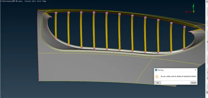
Using universal delete we are deleting the cut surfaces
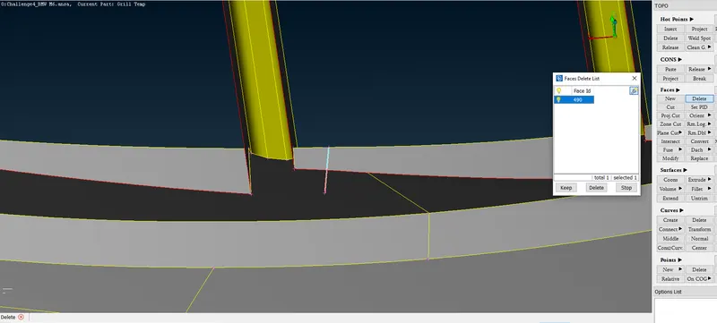
We delete this face as this is not required.
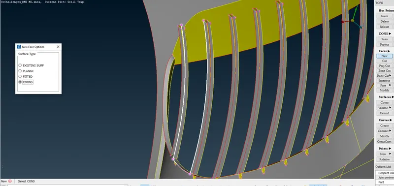
We creating new faces using New under Faces in TOPO.
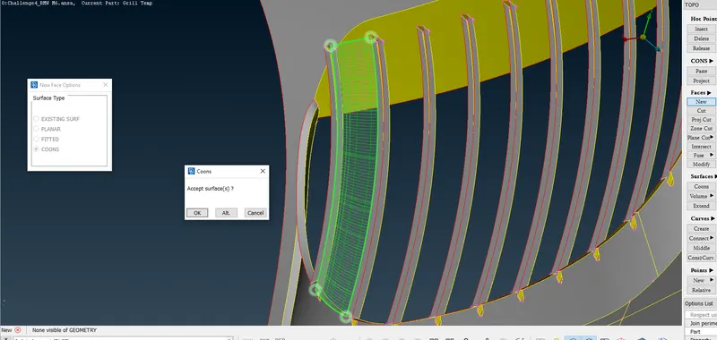
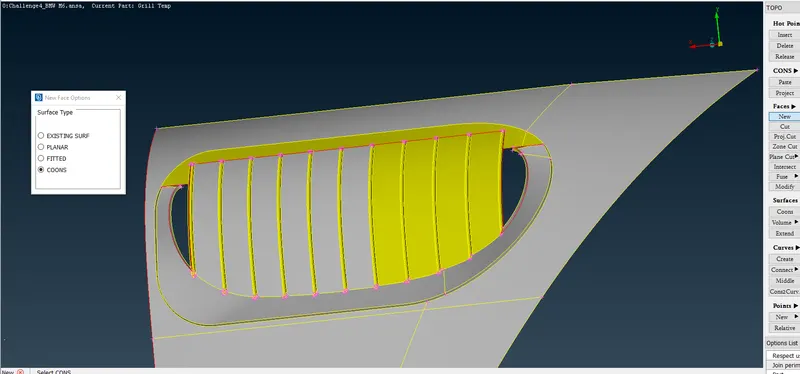
Similarly using the above procedure of creating new faces, we have created the new faces as shown in the above image.
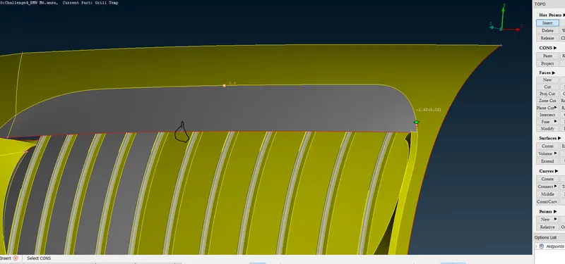
Created a hot point for plane cut
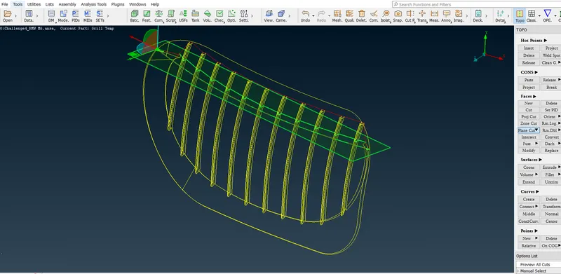
Using three point on the curve we create a plane using plane cut option.
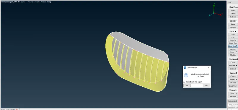
On clicking Yes on the newly pop up window we create plane cut.
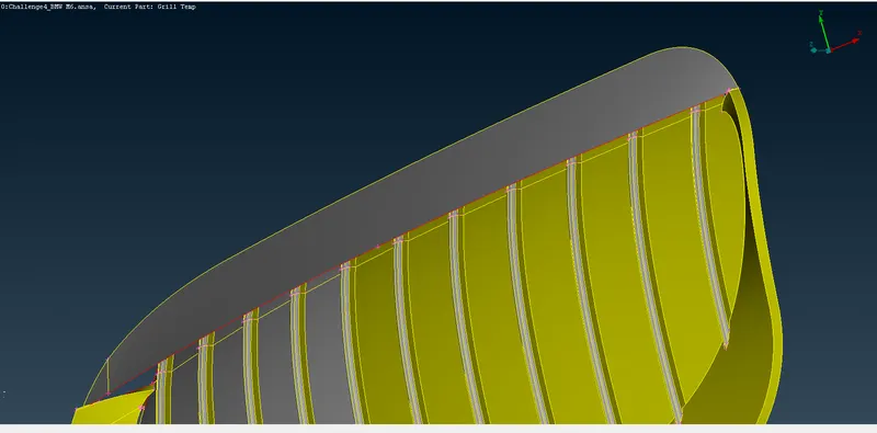
We can see the plane cut generated on the grill and surface.
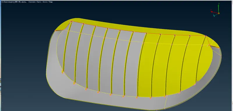
Using Not option we can hide the required portion.
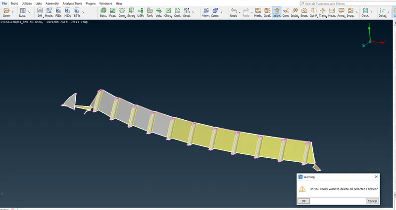
Now we can delete the undesired or not required portion using the universal delete option.
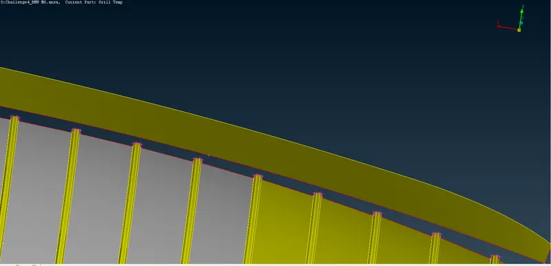
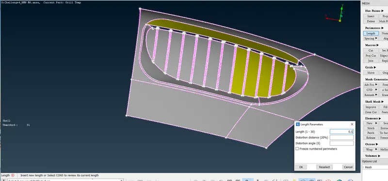
We set the resolution of the selected geometry to 0.1 as shown in the above figure.
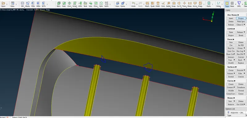
Now we project the hot points, using Project under Hot Points in TOPO. The hot points are projected which are shown in blue encircled.
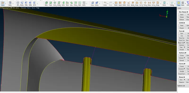
We create curves using Create under Curves in TOPO.
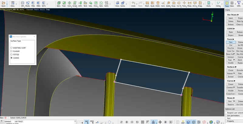
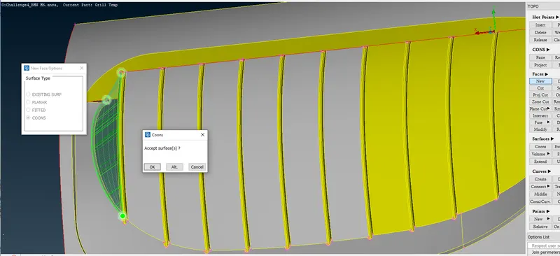
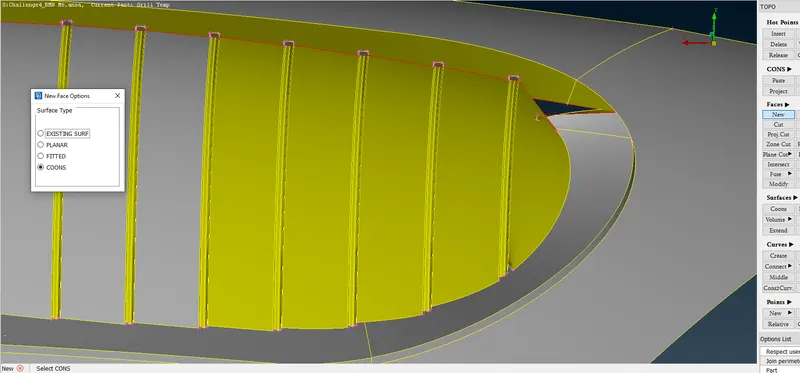
The highlighted cons are selected using New under Faces in TOPO. A new window pops up where we select COONS option.
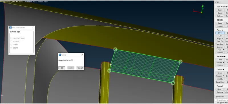
On middle click of the mouse a new face is generatedshowing a temporary view.
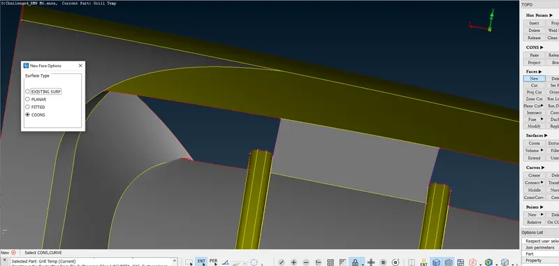
A surface has been created
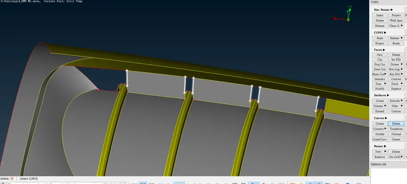
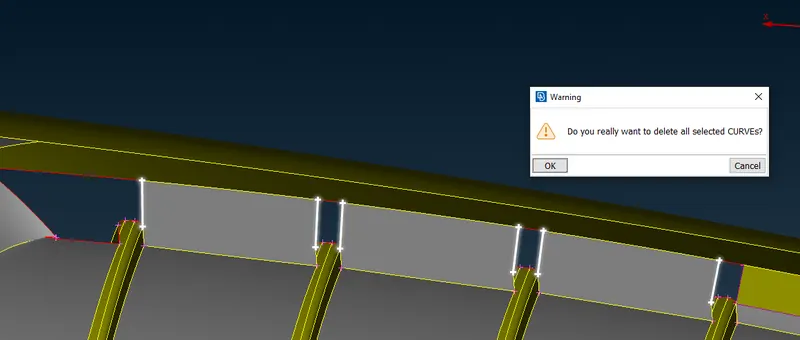
Similarly we will be creating the surfaces.
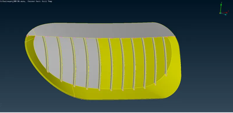
Now the Grill3 is done.
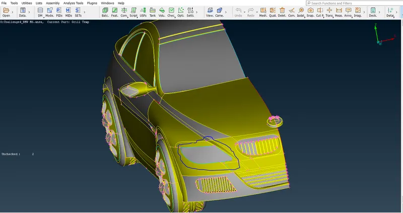
We will now check the blue encircled portion for the errors due to blue cons / triple cons.
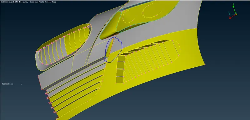
From inside we see that there is an extra projected surface which is forming the blue cons.
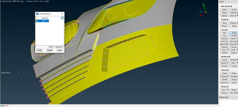
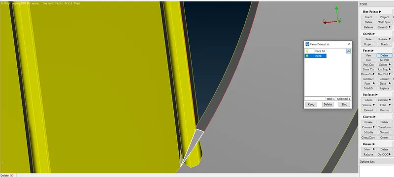
We delete the select face as this is not required.
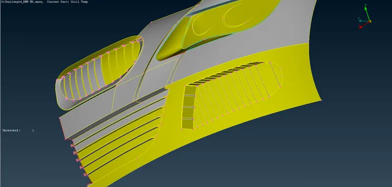
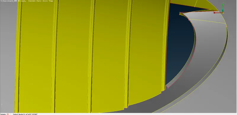
After deleteting the face we see that the one blue cons present is gone.
Now we check for the remaining blue cons
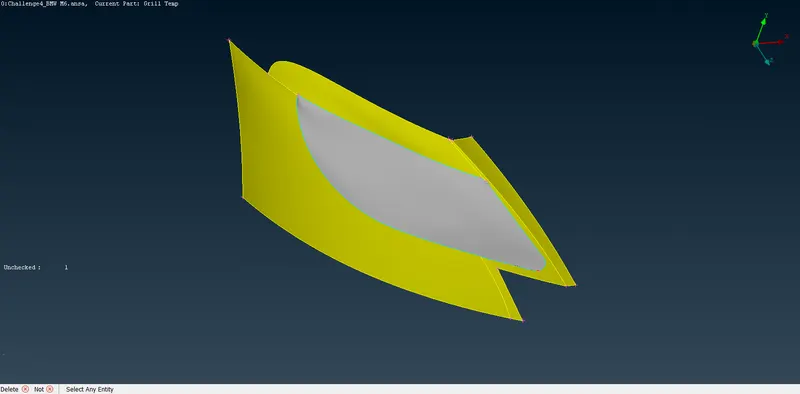
From outside we see that there is one surface where the blue cons is present. From out side it is the perfect shape we require.
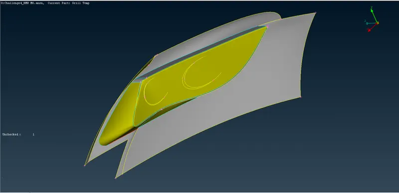
From inside we observe that there is extra surface present which is not required by us as we are are doing the external flow analysis.
Hence we can delete this surface from inside.
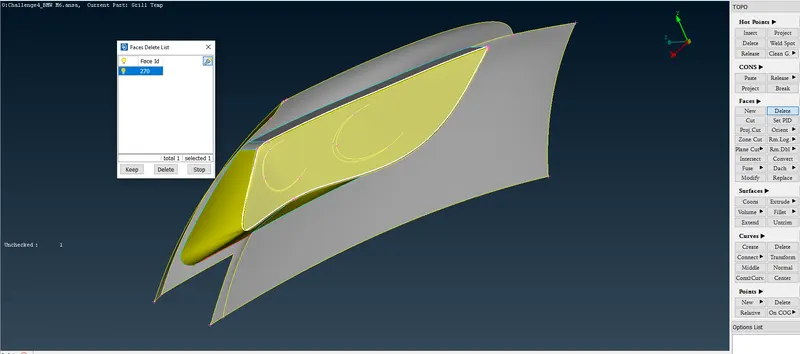
We delete the selected face as this is not required.
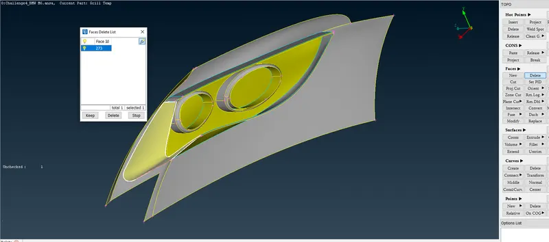
We delete the selected face as this is not required.
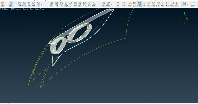
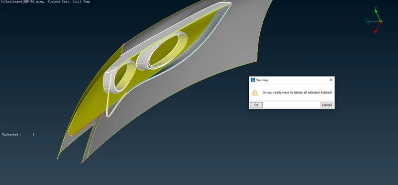
We delete the selected surface using universal delete.
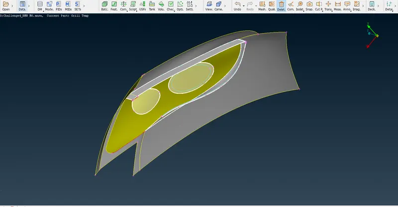
We delete the selected surface using universal delete.
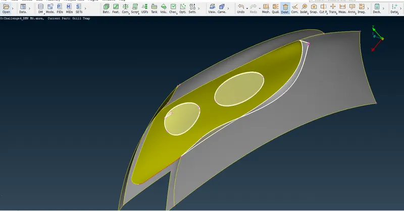
We delete the selected surface using universal delete.
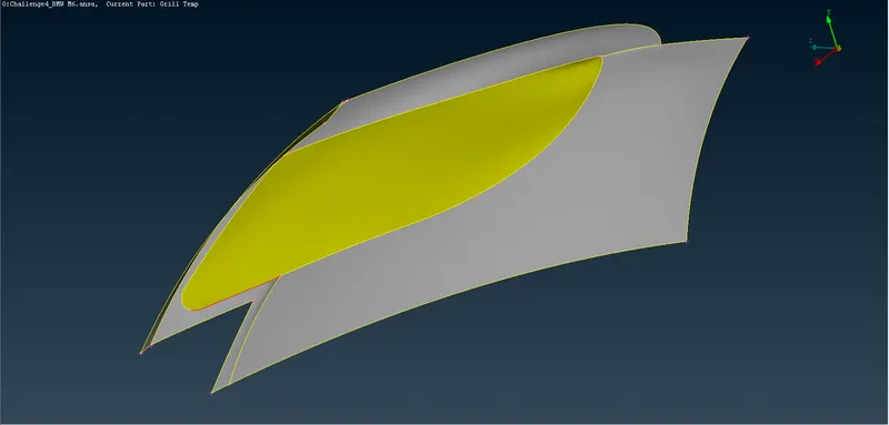
In the above image we see one red cons is present.
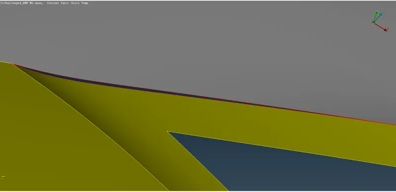
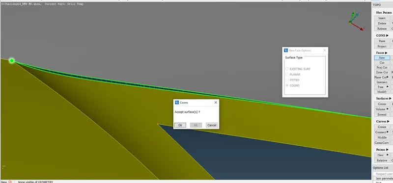
We create a new as shown in the above image.
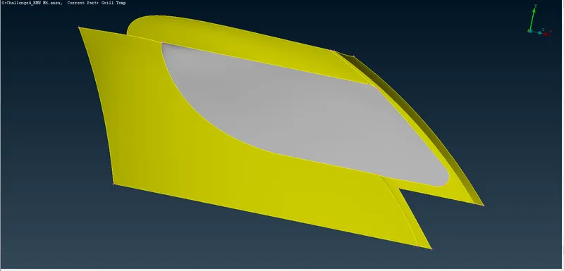
All the errors are resolved in the above part.
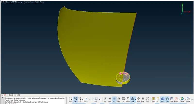
Now we work on the BMW logo. We have isolated the part in the image using Not option.
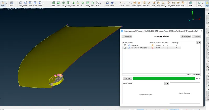
We do the geometry check using Checks Manager.
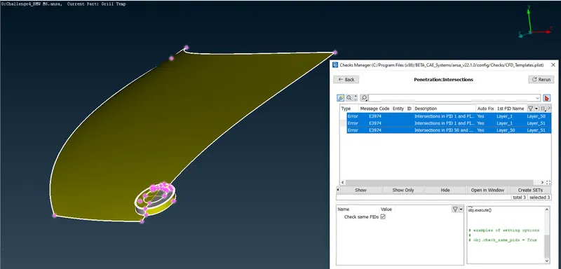
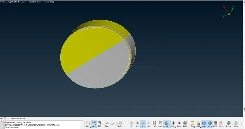
We have isolated the above and we start deleting the surface which are creating the inside volume.
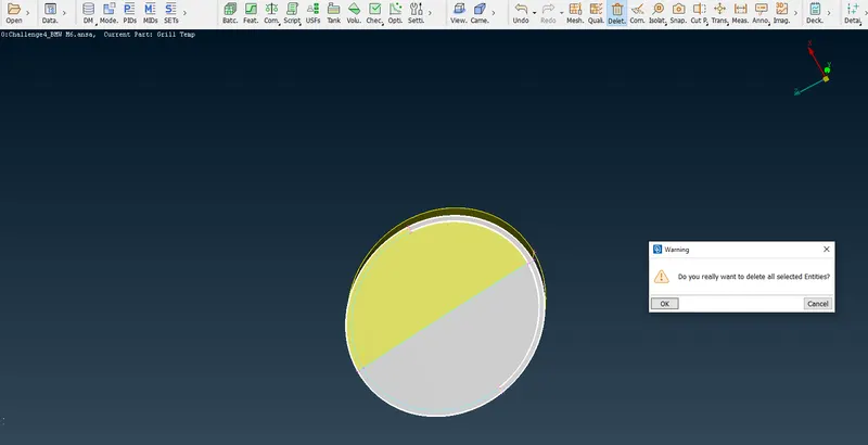
We have selected the after clickin the universal delete.
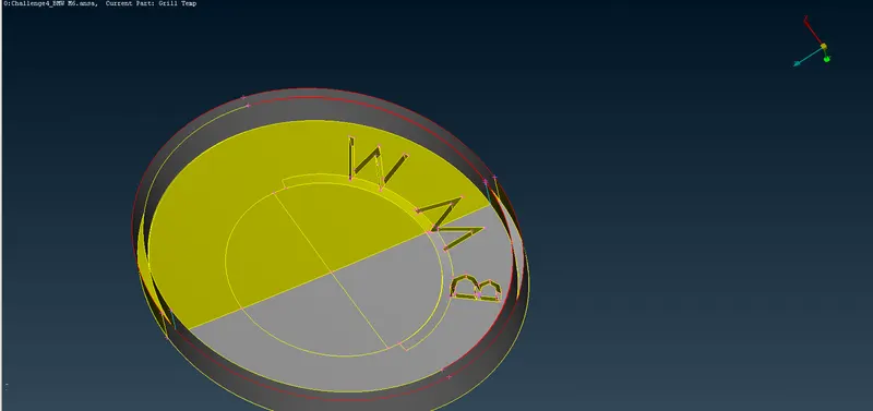
After deleting using universal delete we see there is an inside surface in the logo.
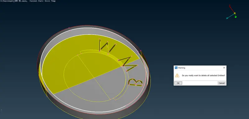
We delete the internal surface using universal delete.
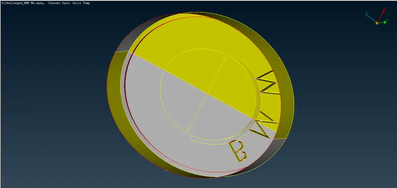
After deleting the internal surface we see there is one red con present near the lettering.
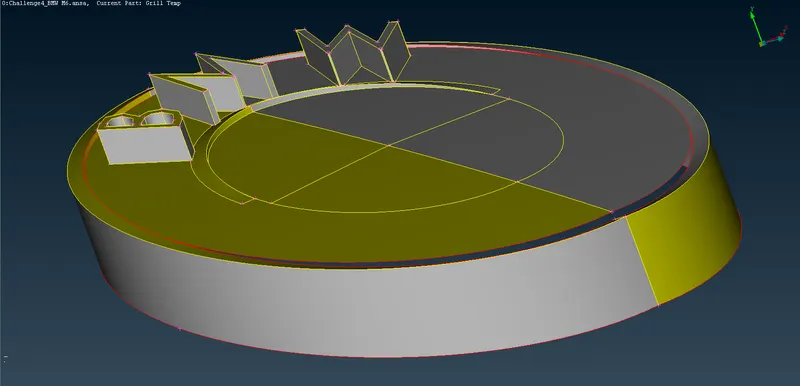
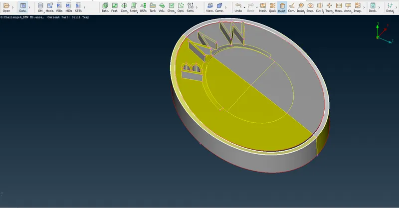
We delete the selected surfaces
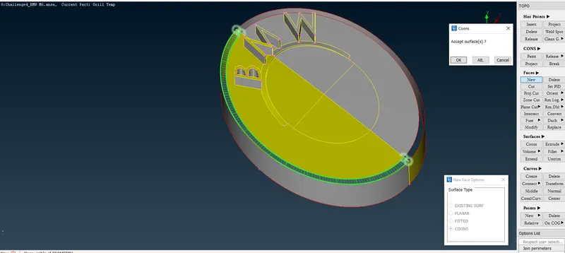
We create the new surfaces as shown in the above image.
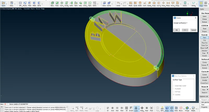
We create the new surfaces as shown in the above image.
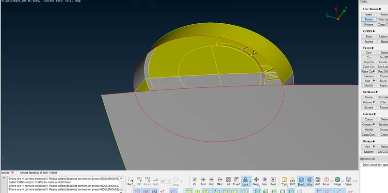
We delete the extra hot points present.
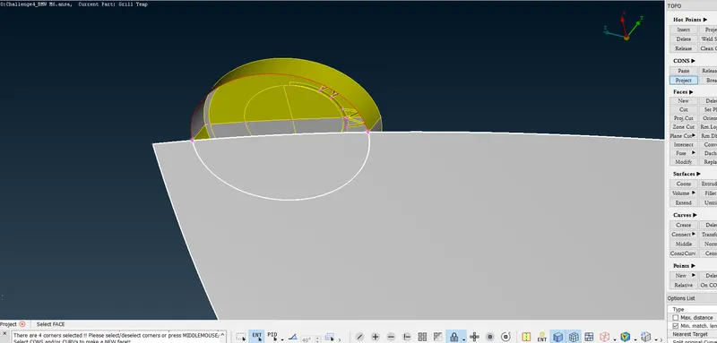
We project the cons from the logo to the selected surface as shown in the above image.
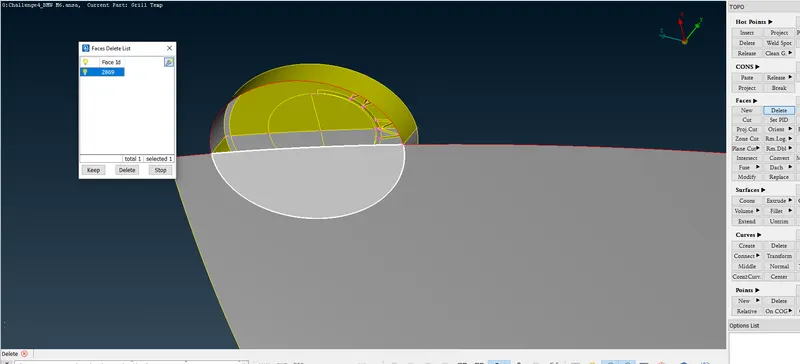
We delete the selected face as shown in the above image.
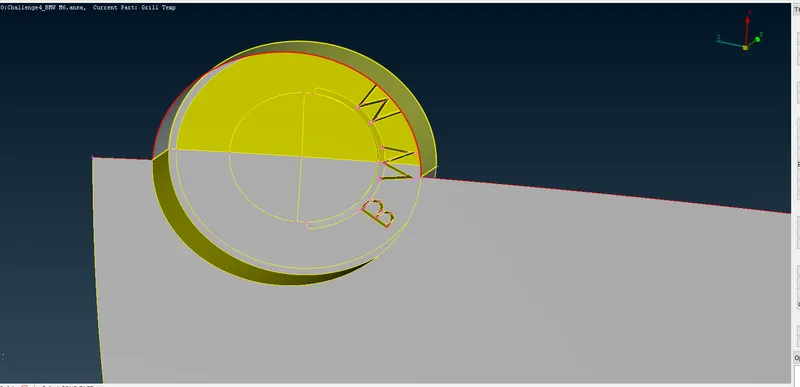
The logo after deleting the surfaces where the intersection error was present.
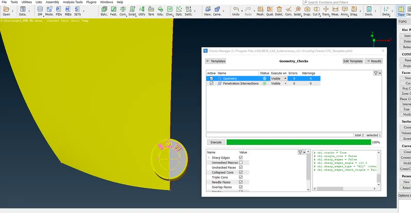
BMW logo after doing the geometry check using Checks Manager. We see that the intersection error are resolved.
Now we will see the warnings that has been shown by the Checks Manager.
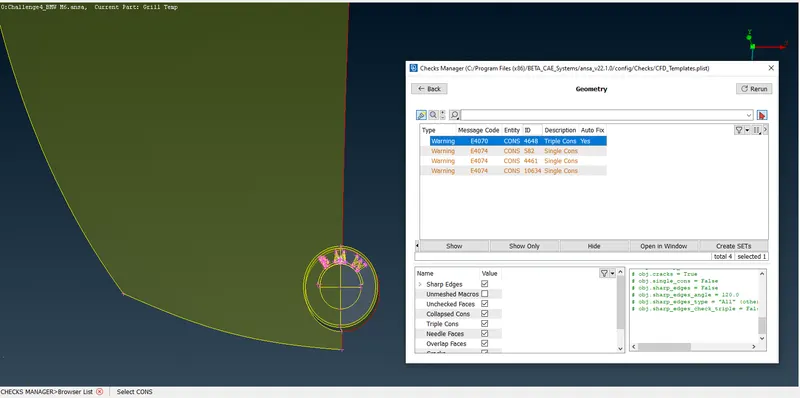
We attempt to resolve the triple cons present.
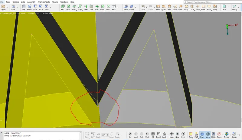
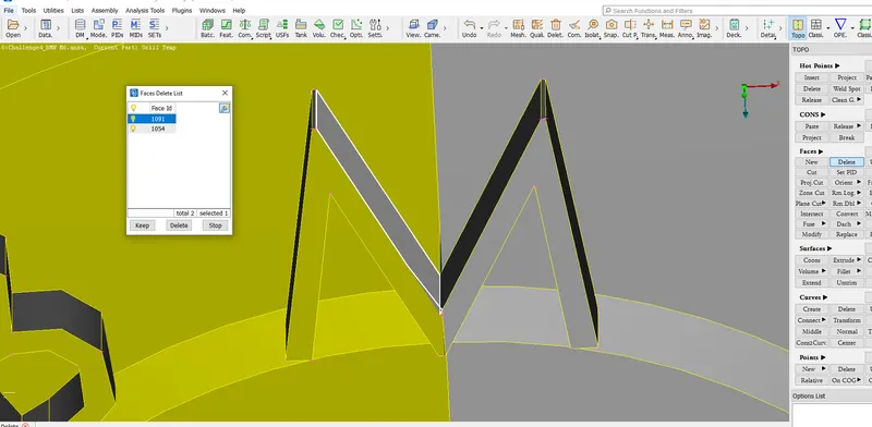
We delete the selected face.
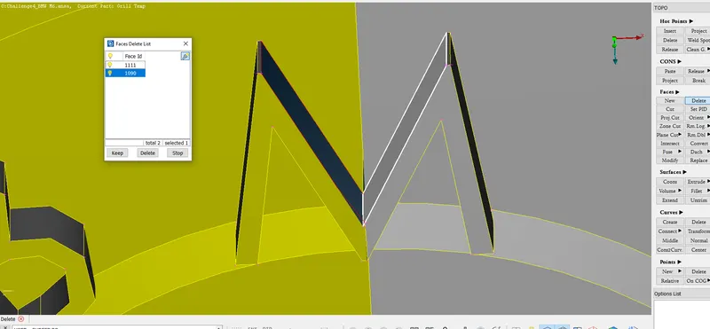
We delete the selected face.
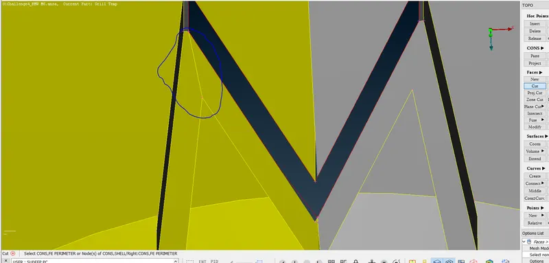
We create cut as shown above.
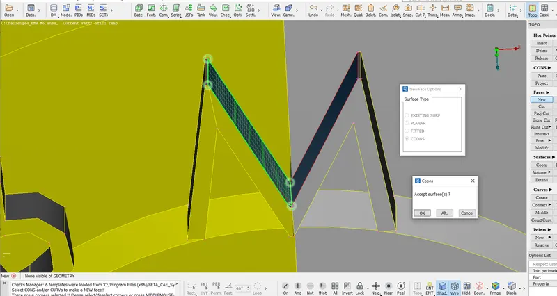
We create the surface as shown in the above image.
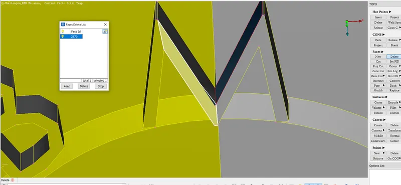
We delete the selected face as this is not required.
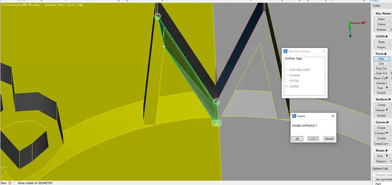
We create the surface as shown in the above image.
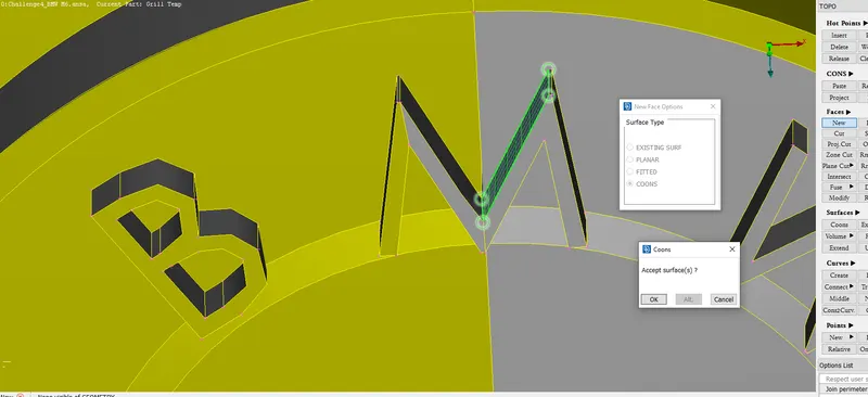
We create the surface as shown in the above image.
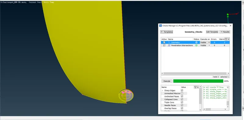
We do the geometry checks using the Checks Manager and found no errors.

There were few warnings which are OK.
With this I have successfully completed the Geometry clean up of the logo.
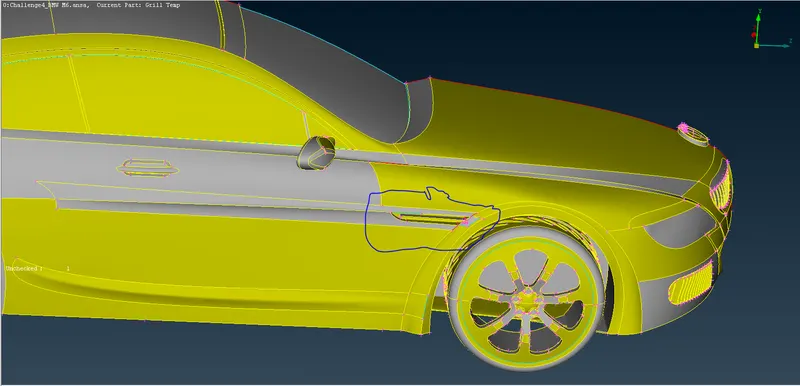
Now we attempt to resolve the errors in the blue encircled portion.
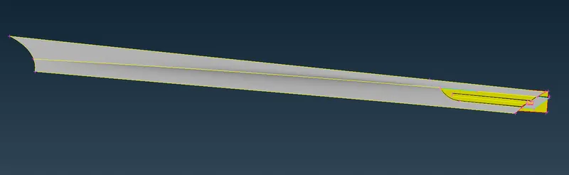
The surface has been isolated using Not option
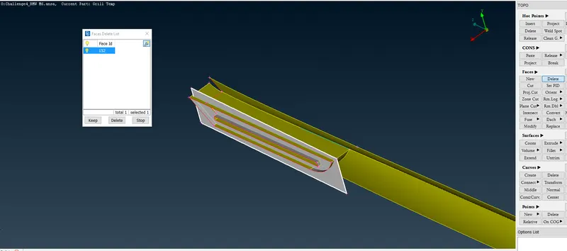
We delete this face as this is intersecting and it is present inside the car.
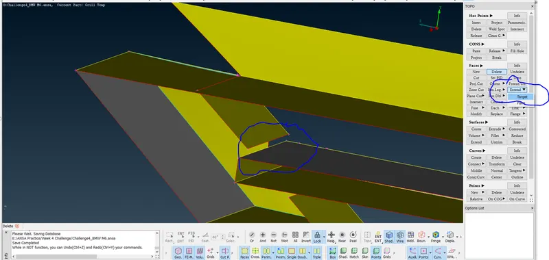
Only red cons can be extended using Extend under Faces in TOPO.
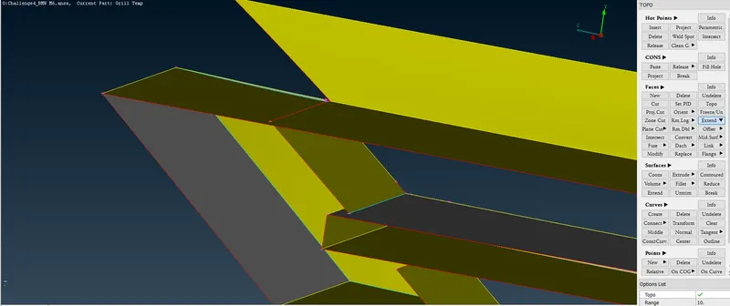
We select Target under Extend, then click the red cons to be extended do the middle click on the mouse, select the surface on which red con surface is to be extended and do the middle click on the mouse.
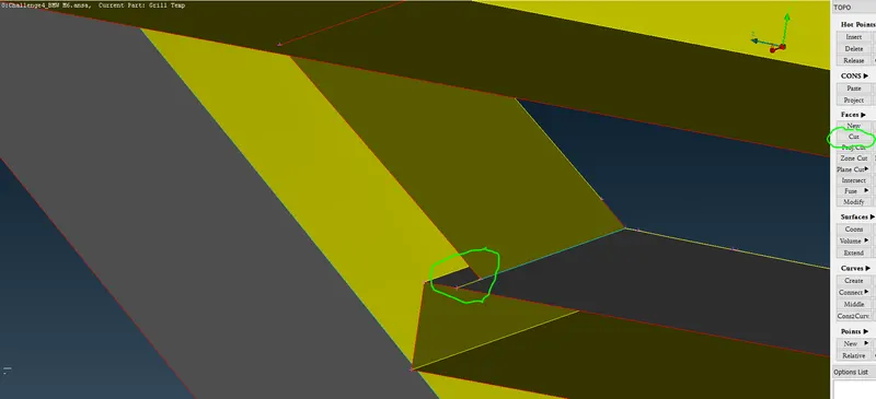
Using Cut option I am creating the cut as shown in the above image.
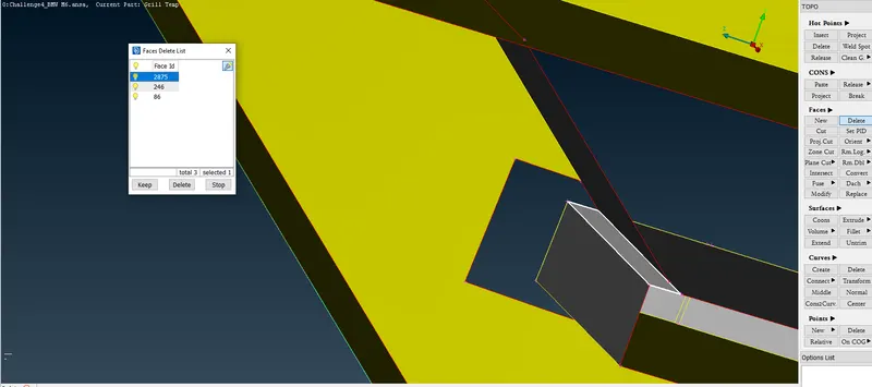
The selected surface is deleted using Delete option as this is not required.
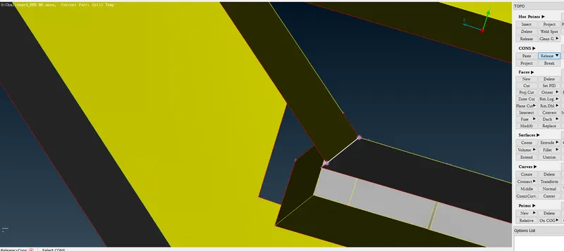
Using the Release option under CONS in TOPO we are converting the selected cons to red cons from double cons
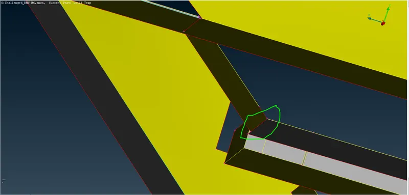
Using Not option we are hiding the surface on the red cons was extended.
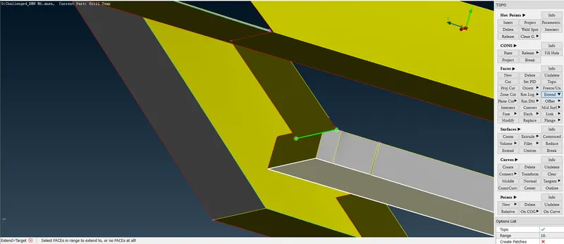
Now again I repeat the procedure to extend.
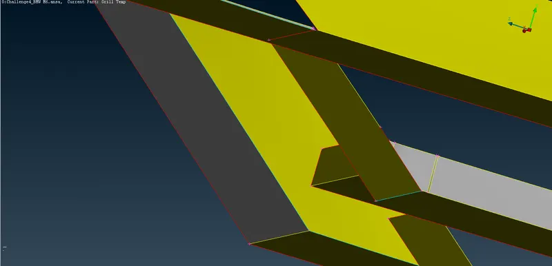
Now I create a cut and delete the unwanted faces.
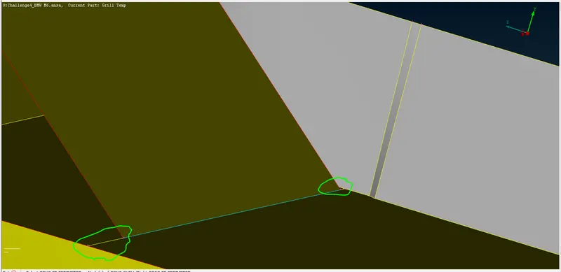
Cut is created in the green encircled position.
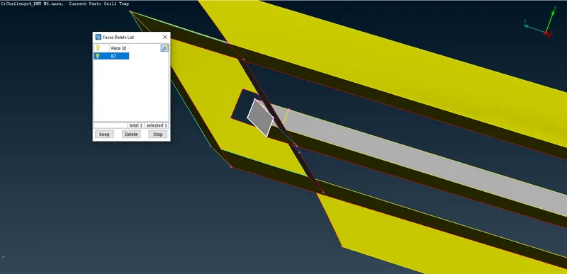
We delete the selected surface.
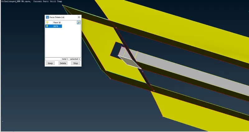
We delete the selected surface.
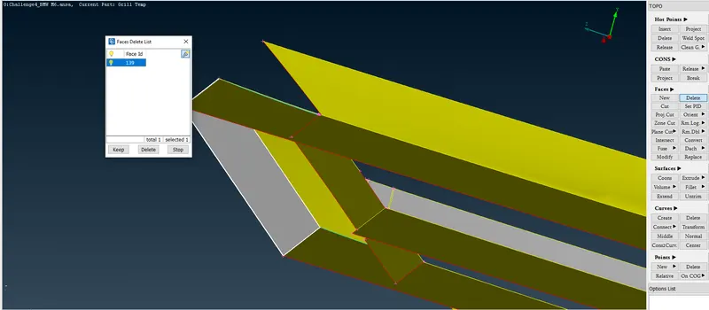
We delete the selected surface.
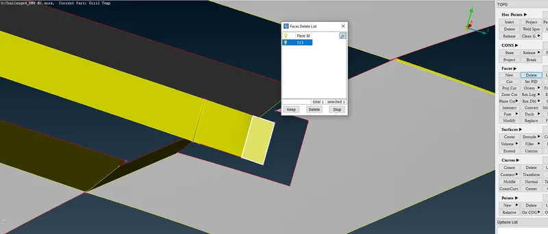
The surfcace seleted in the above image is deleted.
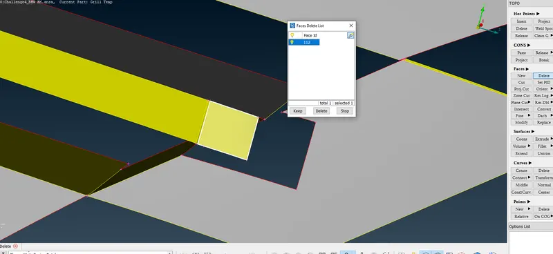
The surfcace seleted in the above image is deleted.
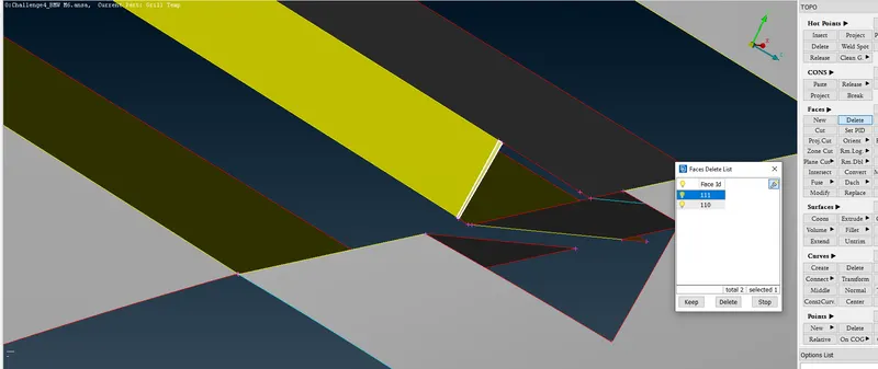
The surfcace seleted in the above image is deleted.
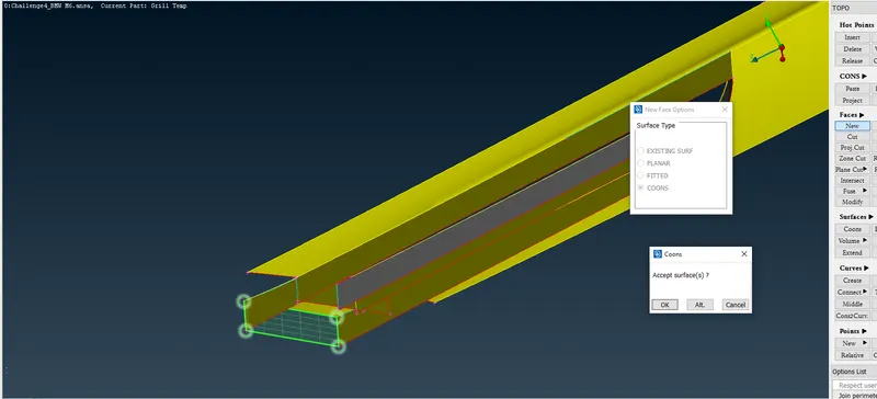
We create a surface as shown in the above image.
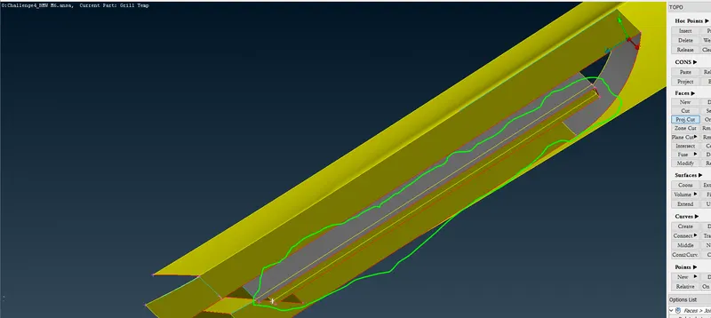
In the green circled portion project cut has been applied.
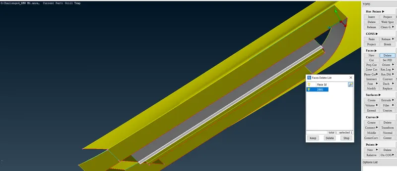
The surfcace seleted in the above image is deleted.
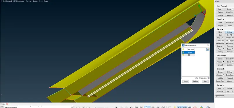
The surfcace seleted in the above image is deleted.
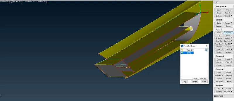
The surfcace seleted in the above image is deleted.
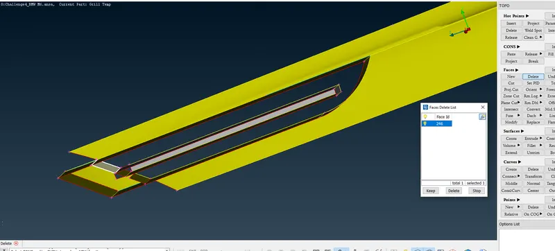
The surfcace seleted in the above image is deleted.
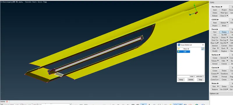
The surfcace seleted in the above image is deleted.
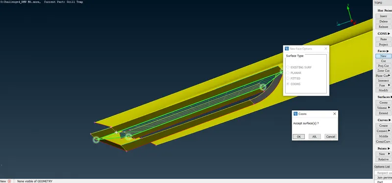
The surface is created as shown in the above image.
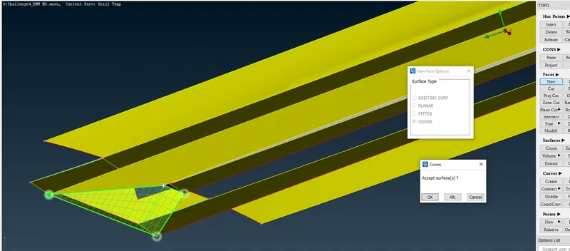
The surface is created as shown in the above image.
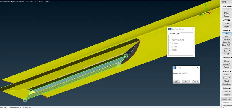
The surface is created as shown in the above image.
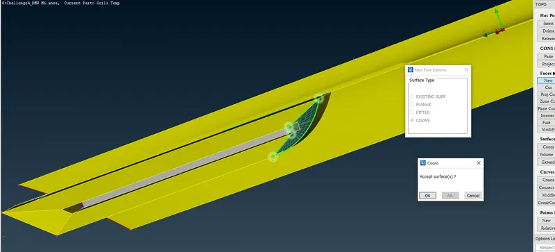
The surface is created as shown in the above image.
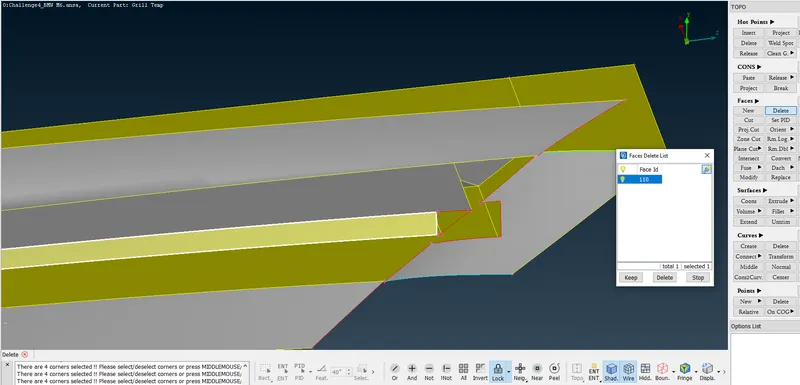
The selected surface in the above image is deleted.
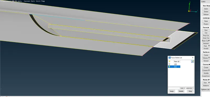
The selected surface in the above image is deleted.
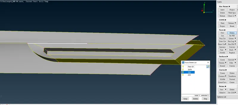
The selected surface is deleted.
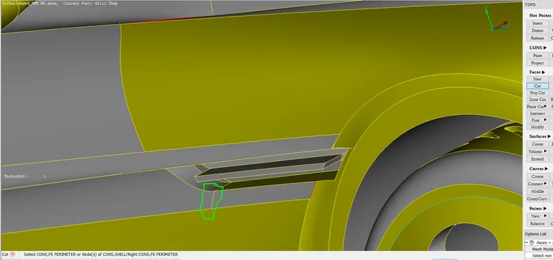
A cut is created in the green encircled portion.
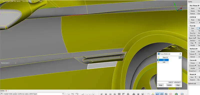
The selected surface is deleted.
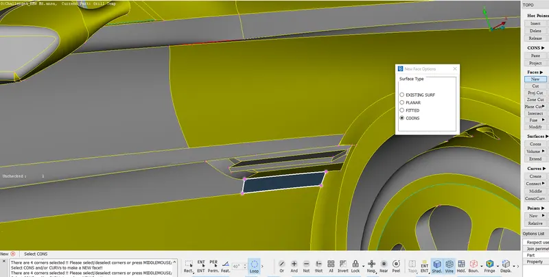
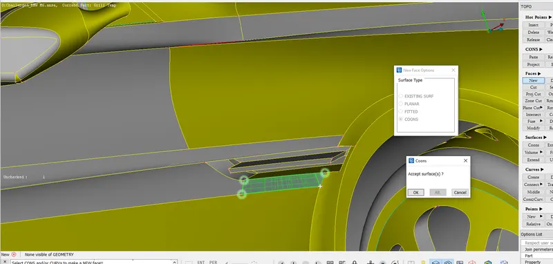
The surface is created as shown in the above image.
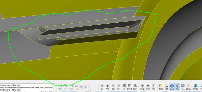
All the errors in the green encircled portion has been resolved.
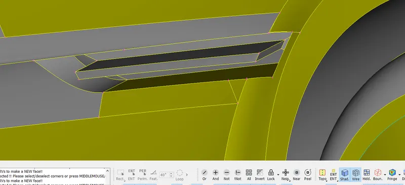
Now I work on the front wind screen . There is triple con present on the front wind screen.
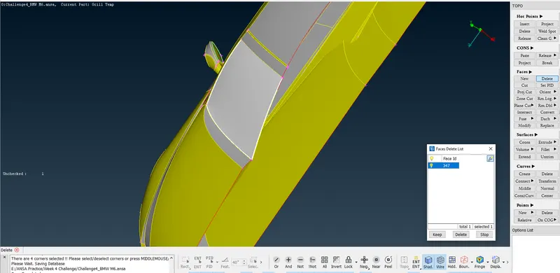
The selected surface in the above image is deleted.
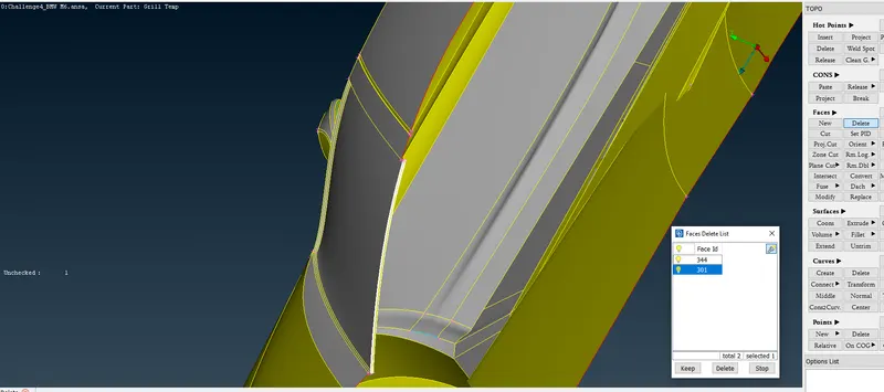
The selected surface in the above image is deleted as this was forming the thickness of the inside extra volume.
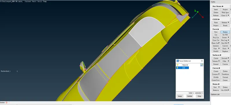
Now front screen error is resolved. I attempt to resolve the back wind screen. The selected surface in the above image is deleted.
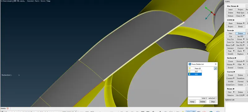
The selected surface in the above image is deleted.
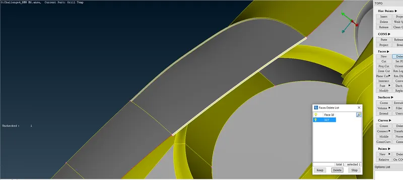
The selected surface in the above image is deleted.
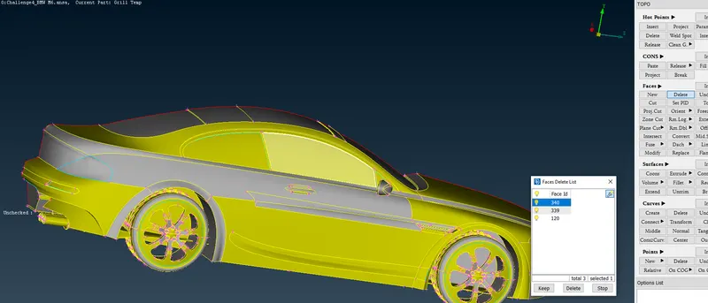
Now I attempt to resolve the error on front window. The selected surface in the above image is deleted.
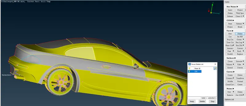
Now I attempt to resolve the error on back window. The selected surface in the above image is deleted.
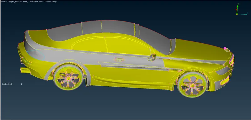
All the wind screen and window errors is resolved.
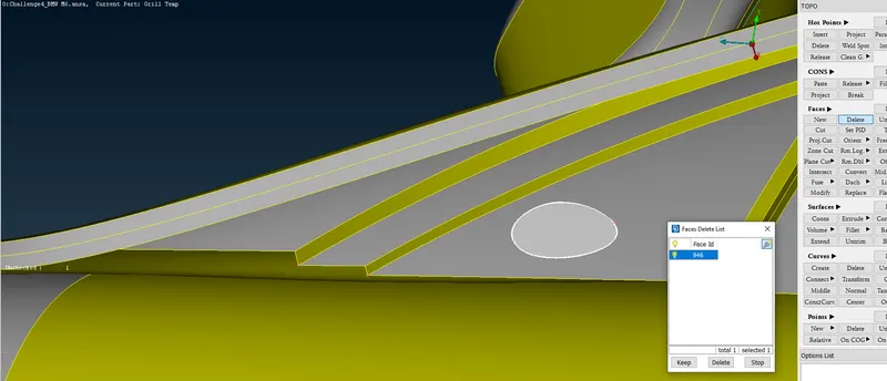
The selected surface in the above image is deleted.
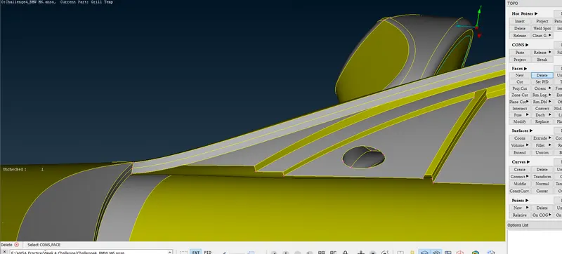
The intersection error at the mirror is taken care.
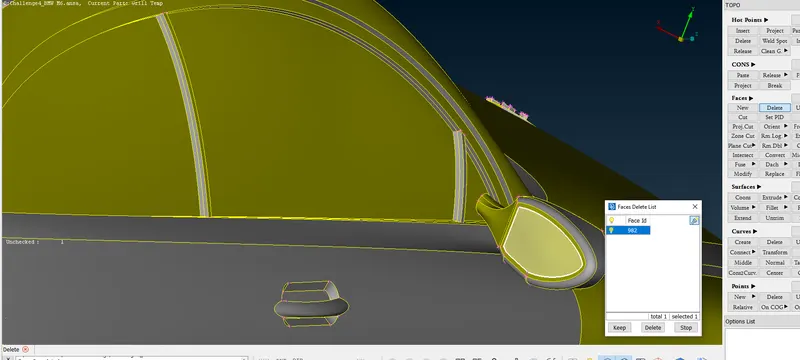
Now I attempt to resolve the error on mirror. The selected surface in the above image is deleted.
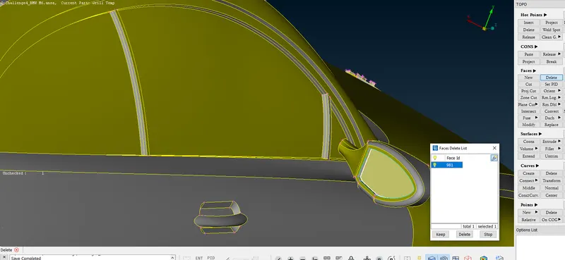
The selected surface in the above image is deleted.
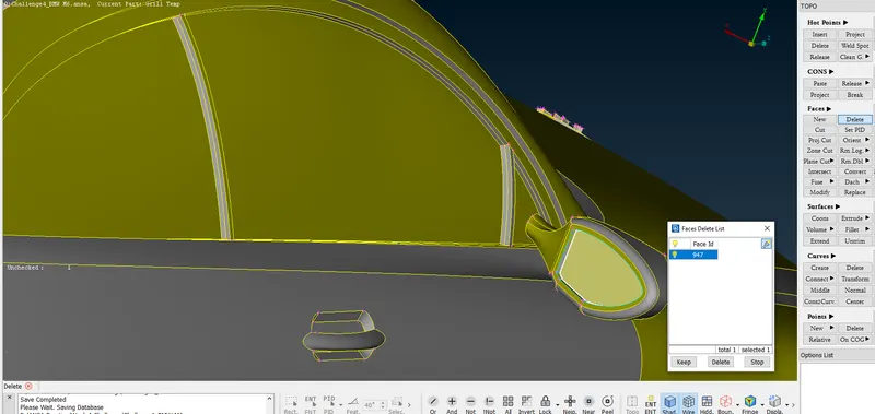
The selected surface in the above image is deleted.
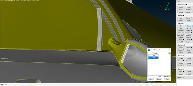
The selected surface in the above image is deleted.
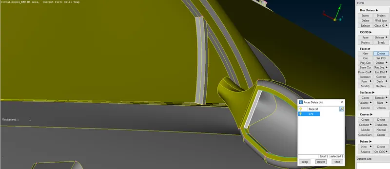
The selected surface in the above image is deleted.
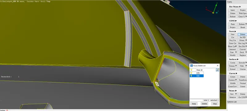
The selected surface in the above image is deleted.
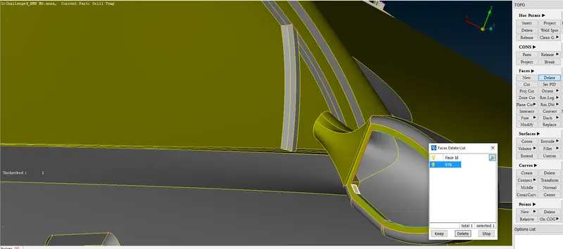
The selected surface in the above image is deleted.
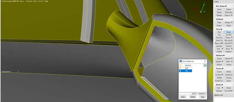
The selected surface in the above image is deleted.
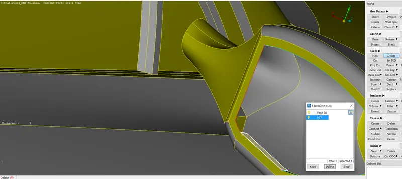
The selected surface in the above image is deleted.
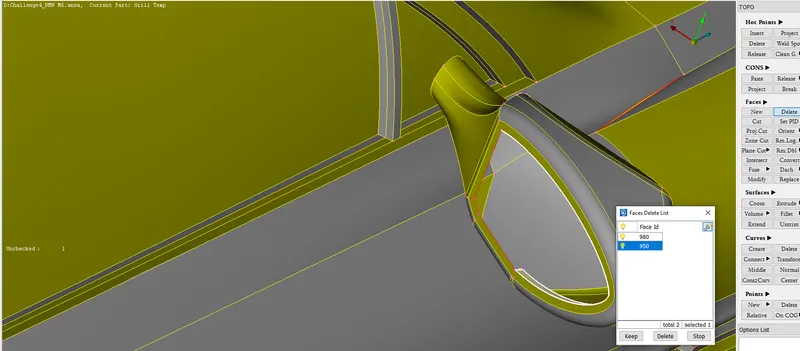
The selected surface in the above image is deleted.
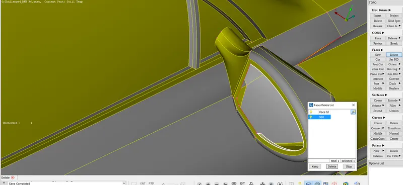
The selected surface in the above image is deleted.
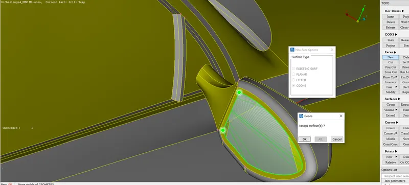
We create the new surface as shown in the above image.
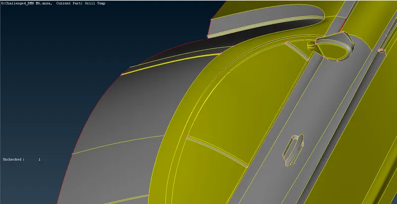
Errors on the mirror has been resolved.
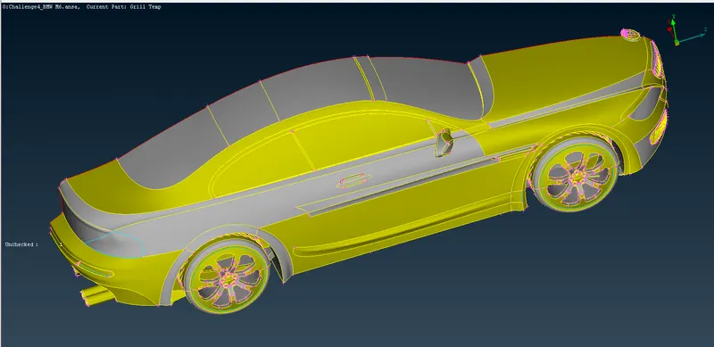
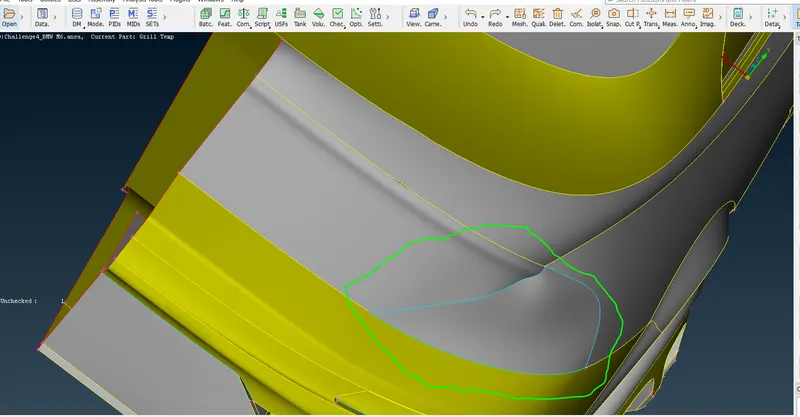
Now I attempt to resolve the green encircled triple cons.
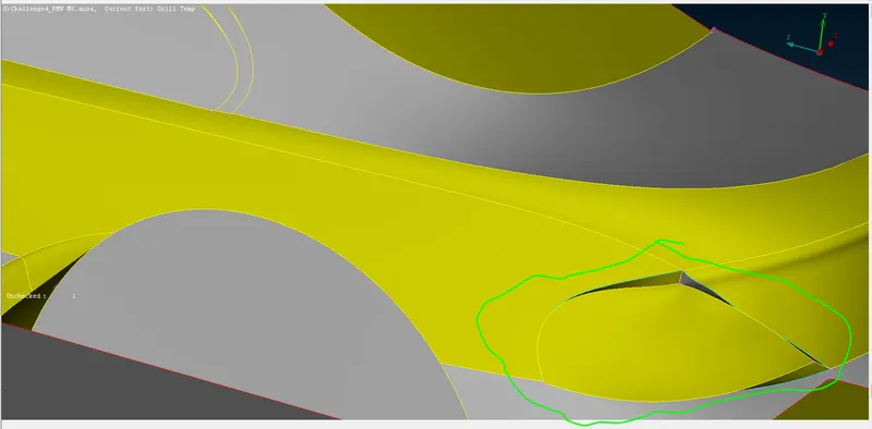
There is an internal volume generated which I can delete as this is not desired.
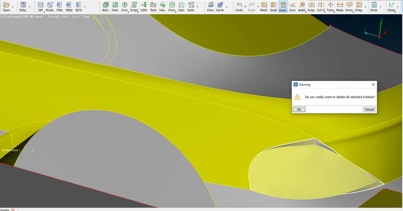
The selected surface is deleted using universal delete.
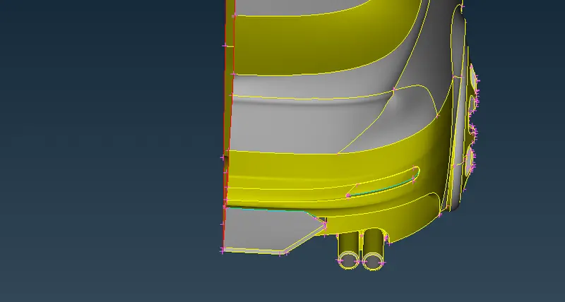
Now he attempt is to resolve the remaining two tripple cons on th back side.
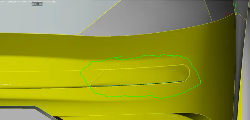
First we attempt to resolve the green encircled one.
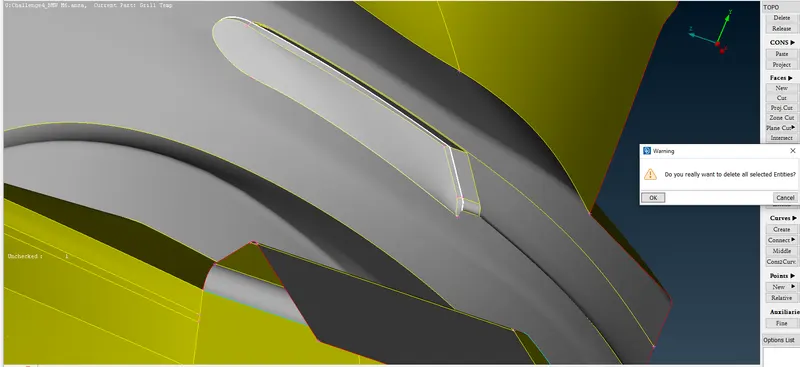
From inside we see that there is an internal volume generated which is not desired. The selected surface is deleted using universal delete.
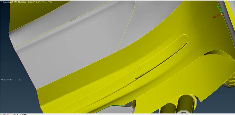
The error is resolved.
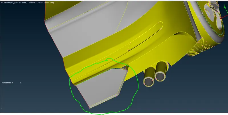
Now I attempt to resolve the green encircled portion.
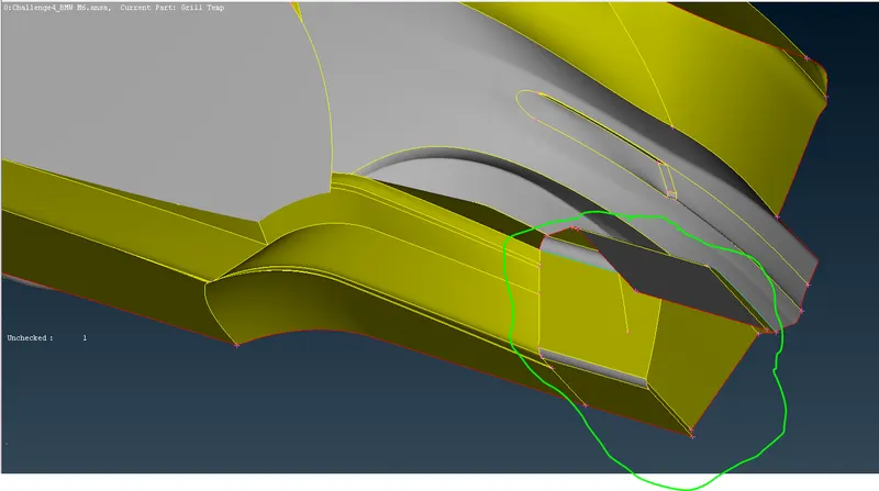
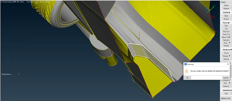
The selected surface is deleted using universal delete.
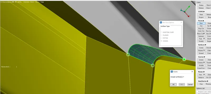
The selected surface is created as shown in the above image after deleting the extra hot points.
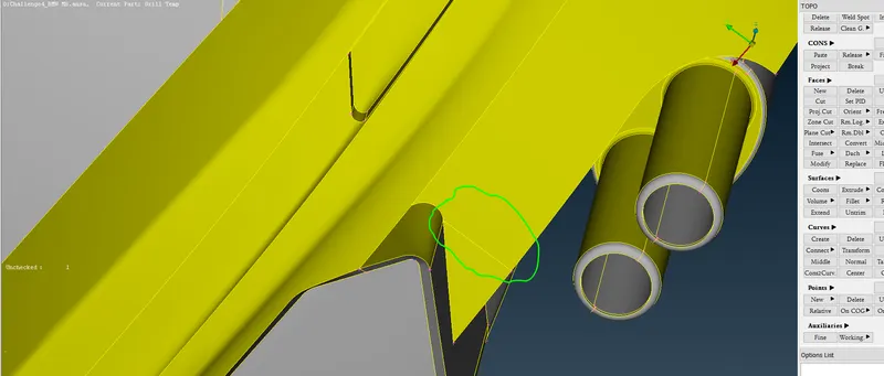
A cut is created as shown in the green encircled in the above image.
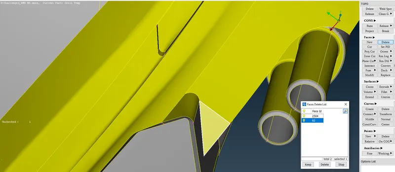
The selected surface is deleted in the above image.
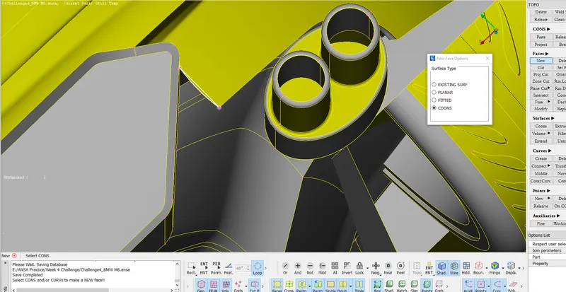
The selected surface is created as shown in the above image because after deleteing the cut portion red con is generated.
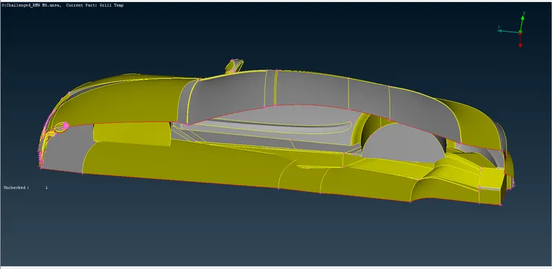
Now I attempt to resolve the errors on the floor.
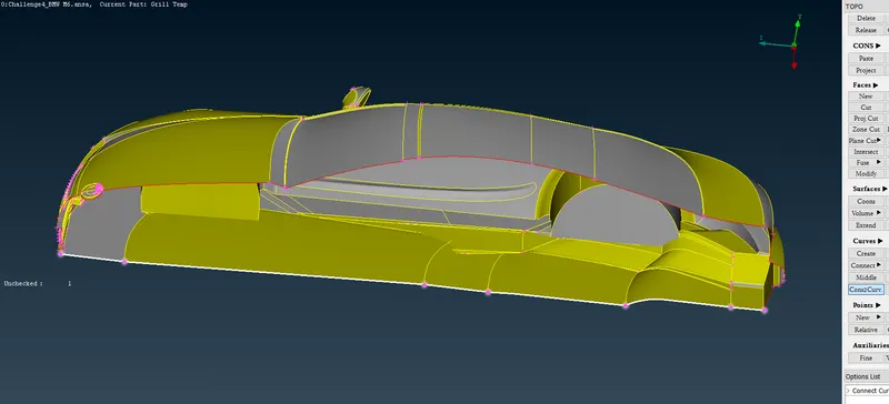
Using Cons2Curv under Curves in TOPO. We create the curves at the highlighted portion.
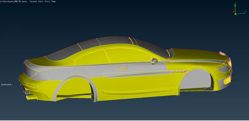
We hide the tyres using Not option along with PID and PID region.
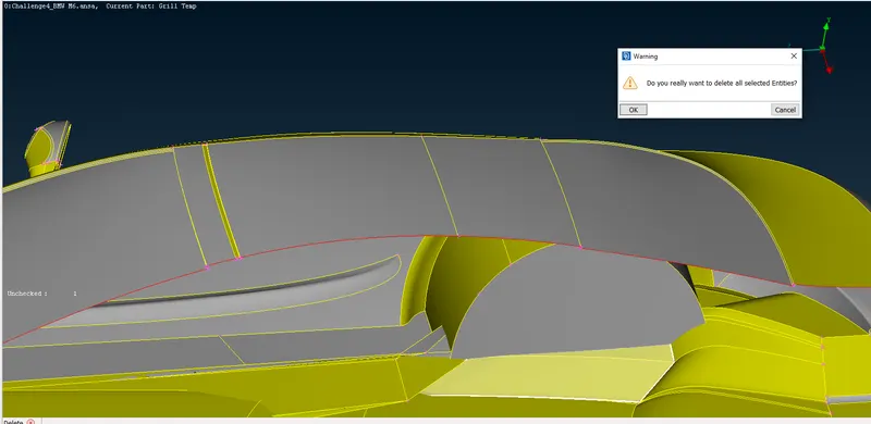
The selected face in the above image is deleted using universal delete.
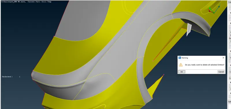
The selected face in the above image is deleted using universal delete.
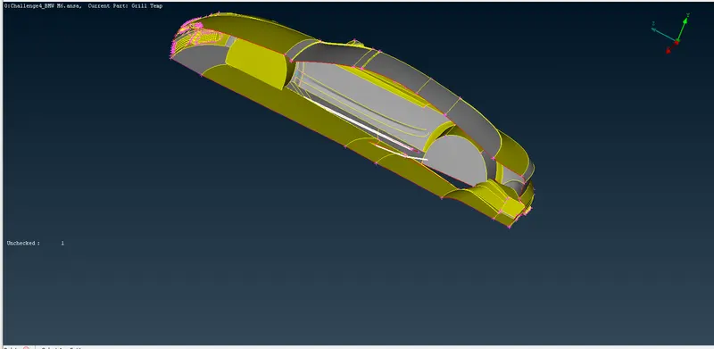
The selected face in the above image is deleted using universal delete.
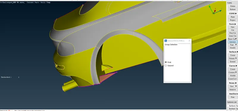
I attempt to delete these surface as shown in the above image by using Intersect under Faces in TOPO.
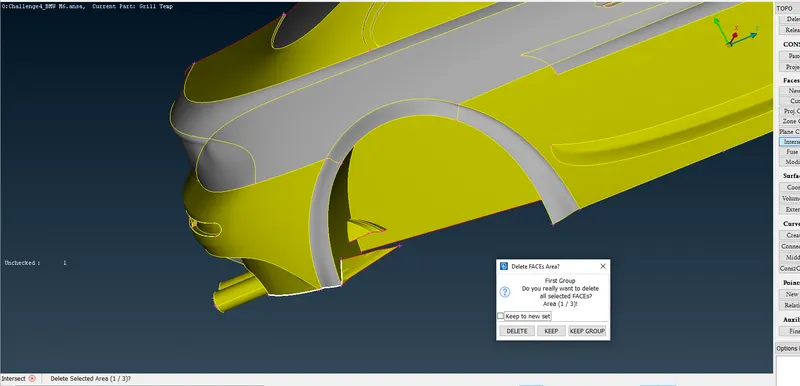
The selected face is kept or not deleted.
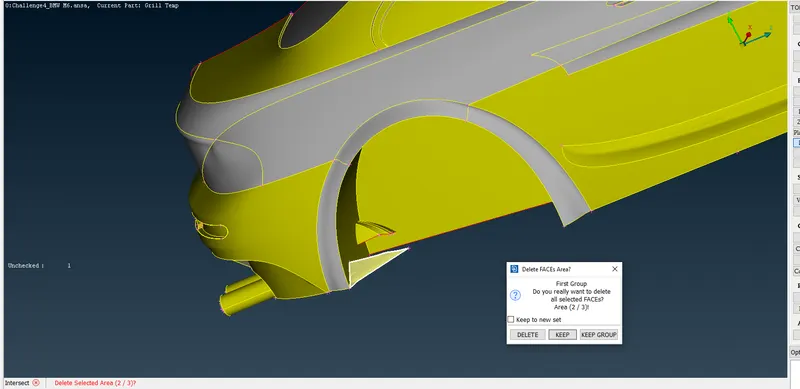
The selected surface in the above image is deleted.
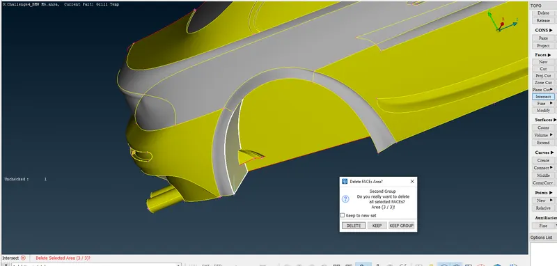
THe selected face is kept or not deleted.
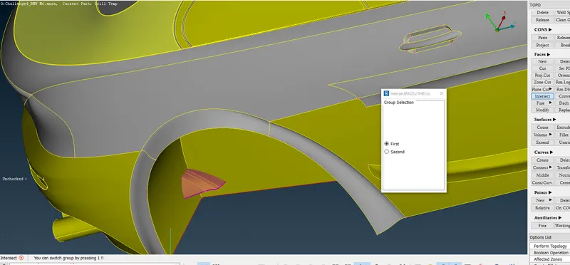
I attempt to delete these surface as shown in the above image by using Intersect under Faces in TOPO.
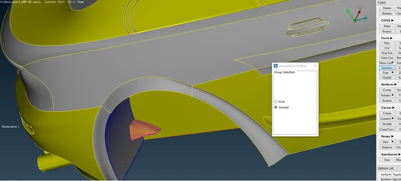
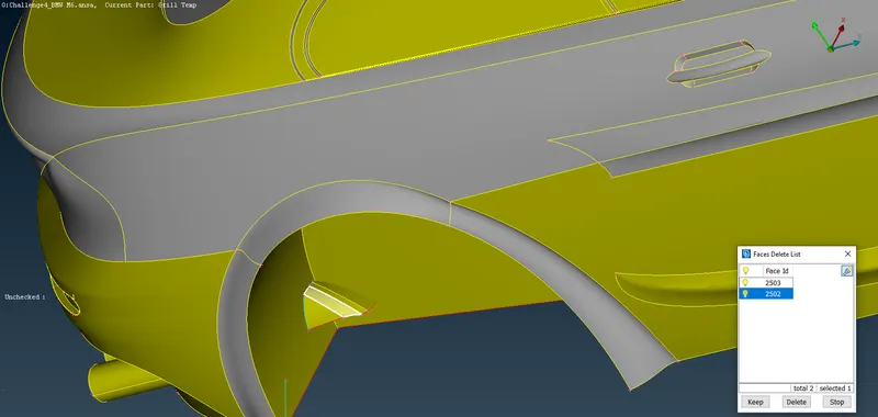
The selected surface in the above image is deleted.
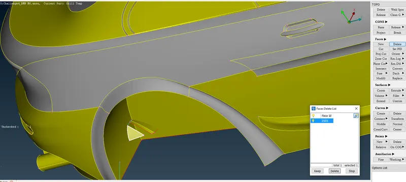
The selected surface in the above image is deleted.
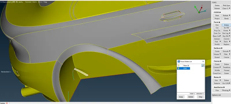
The selected surface in the above image is deleted.
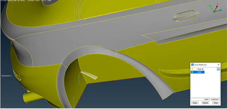
The selected surface in the above image is deleted.
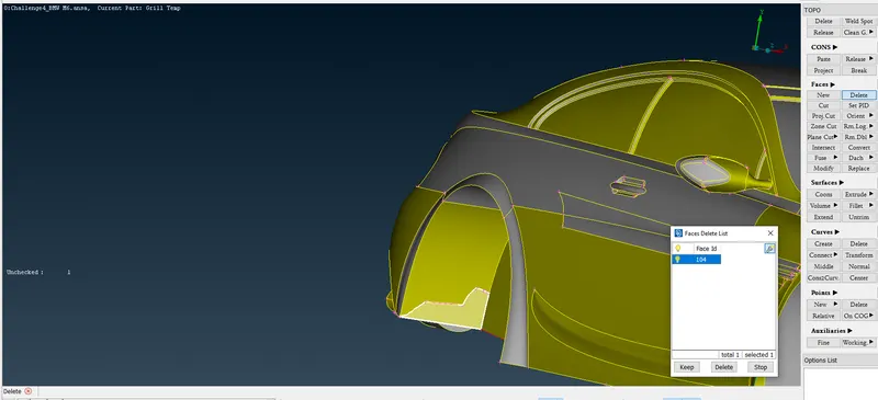
The cut is created using Cut option and the selected surface in the above image is deleted.
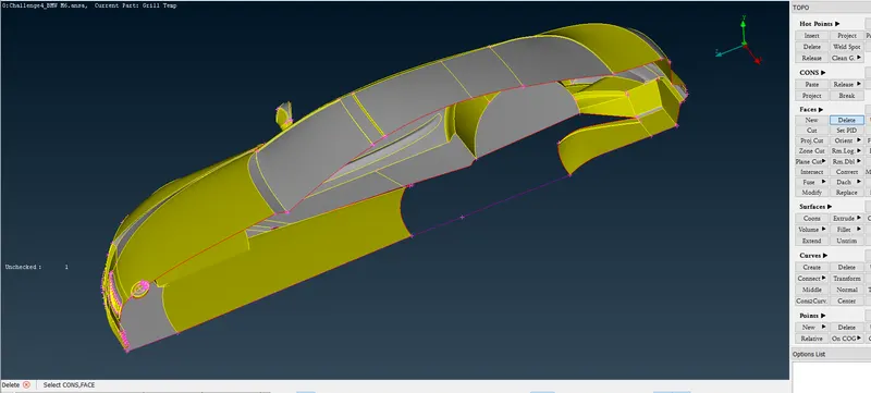
In the above image I have deleted some faces on the floor.
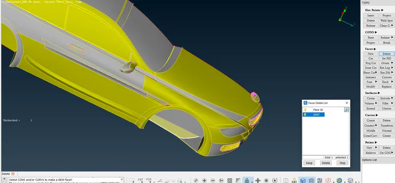
The selected surface in the above image is deleted.
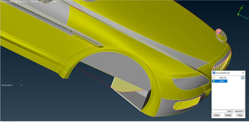
The selected surface in the above image is deleted.
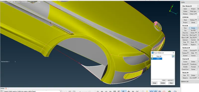
The selected surface in the above image is deleted.
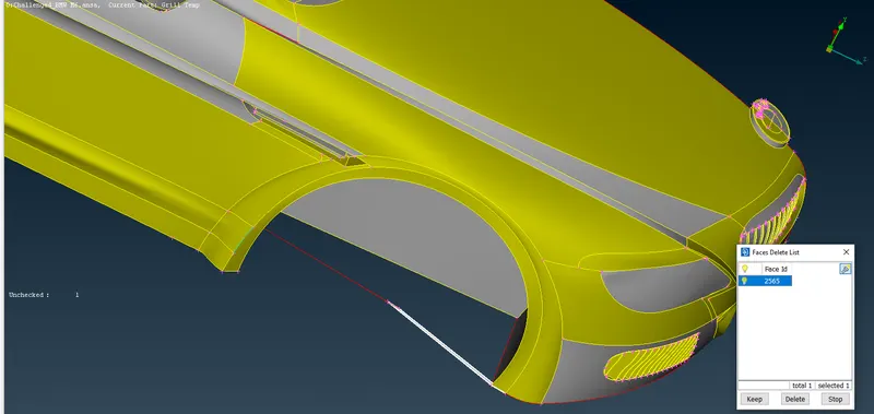
The selected surface in the above image is deleted.
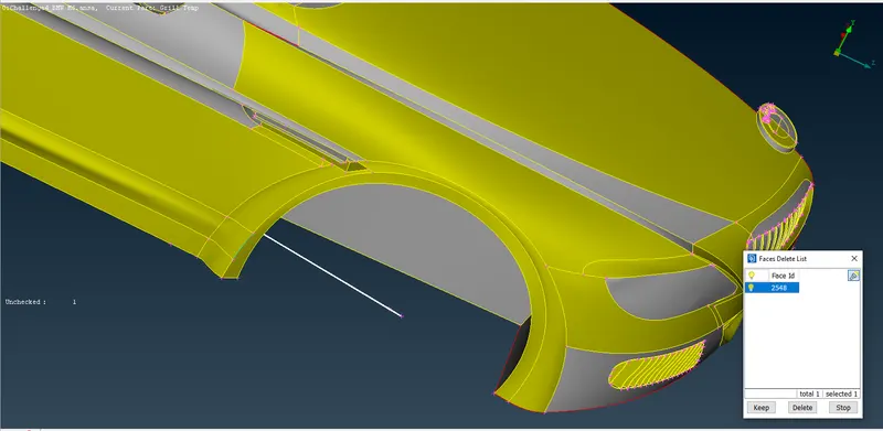
The selected surface in the above image is deleted.
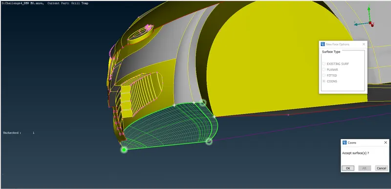
Now I am creating the surfaces / faces on the floor as shown in the above image.
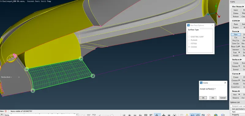
Now I am creating the surfaces / faces on the floor as shown in the above image.
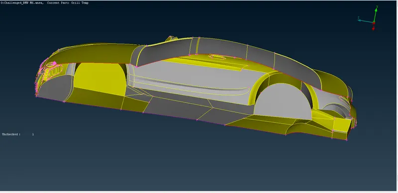
The final look after creating the entire floor of the BMW car.
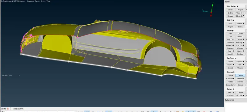
I am deleting the curves created as shown in the above image.
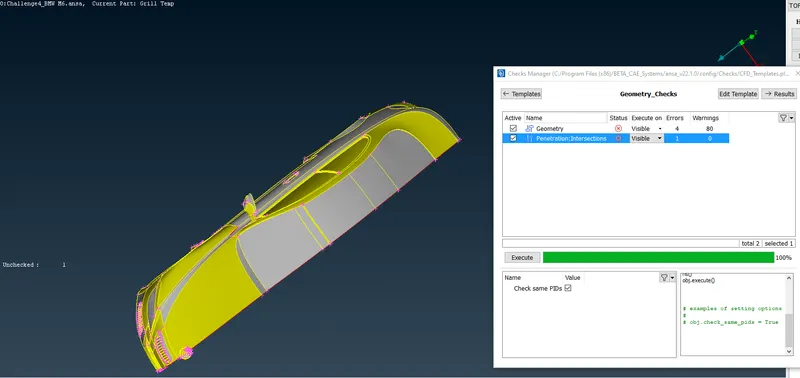
I perform the geometry checks using the Checks Manager.
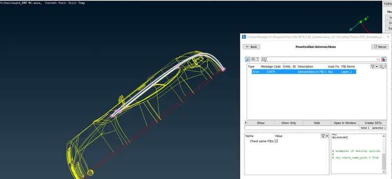
The intersection error is highlighted as shown in the above image which I will try resolve.
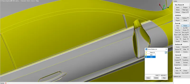
The selected surface in the above image is deleted.
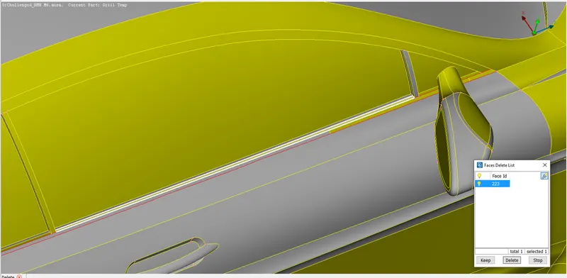
The selected surface in the above image is deleted.
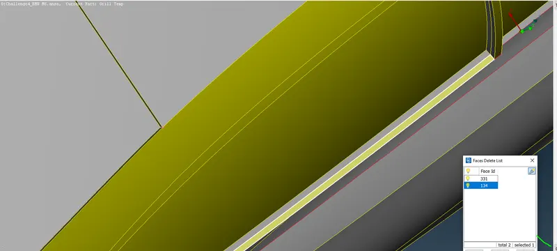
The selected surface in the above image is deleted.
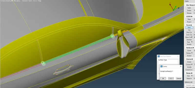
After deleting the surface I create the new surface as shown in the above image.
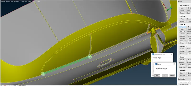
The green highlighted surface / face is created.
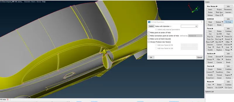
Using Fill Hole I fill the gaps near the door window.
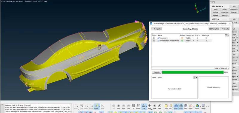
I perform the geometry check sing Checks Manager and conclude that intersection errors are resolved.
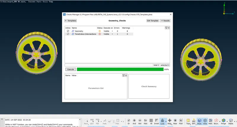
Using Invert operation we isolate the tyres as shown in the above and do the geometry checks using Checks Manager.
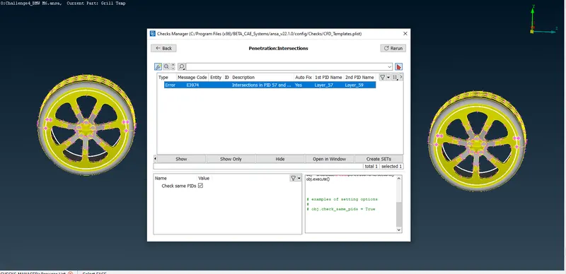
The intersection error present in the tyre is highlighted in the above image.
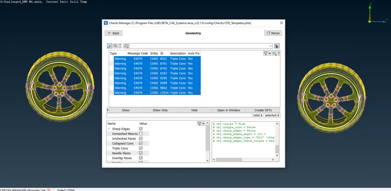
Triple cons are also present in the geometry as warnings which I will try to resolve.
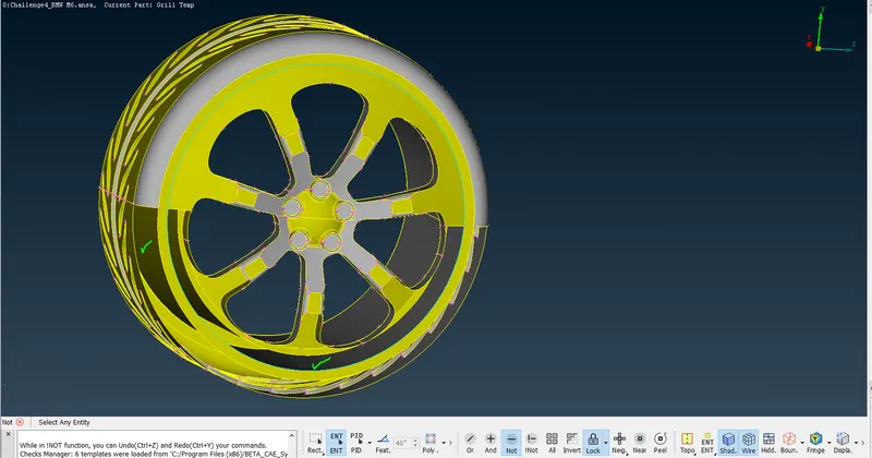
I have hidden some surface from outside using Not. After hiding the faces I am able to able to see th extra face which are causing the triple cons to be formed.
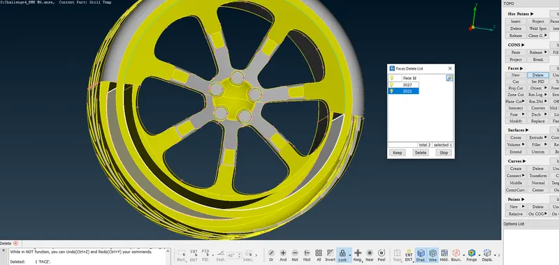
The selected surface in the above image is deleted.
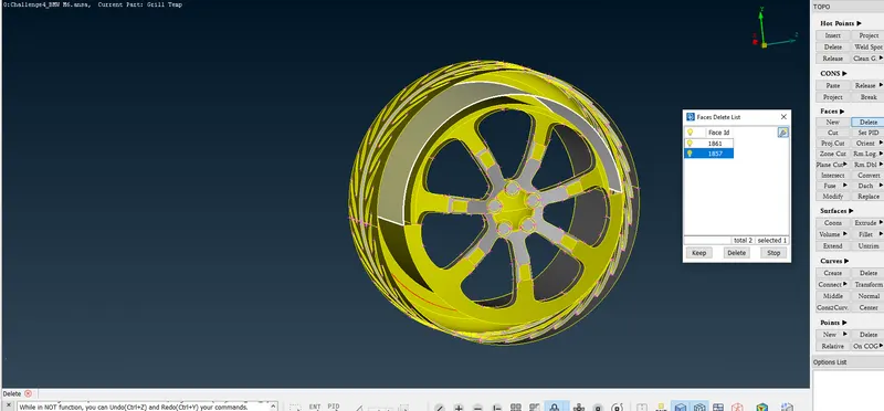
The selected surface in the above image is deleted.
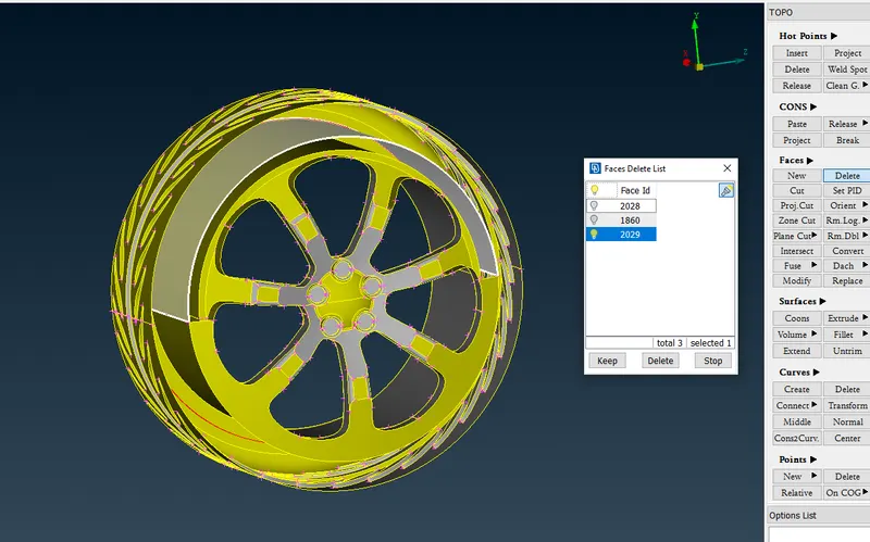
The selected surface in the above image is deleted.
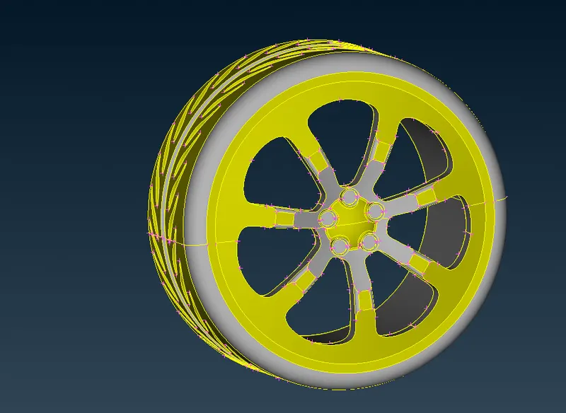
From outside we can see that the triple cons are gone.
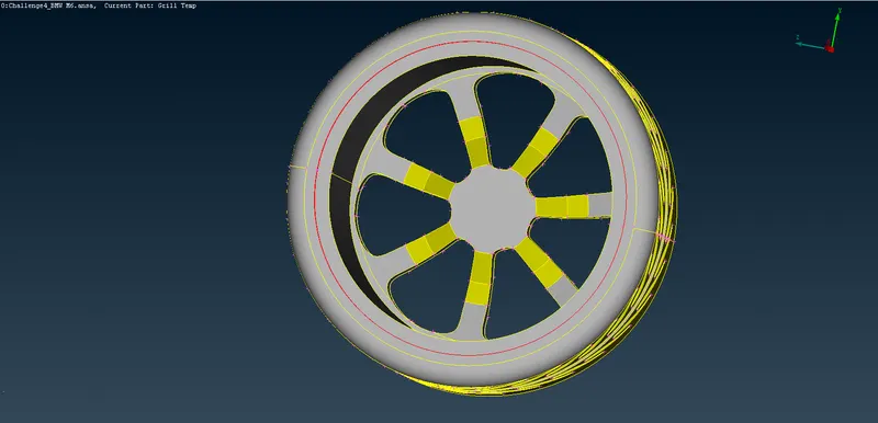
When viewed from the other side we see one red con.
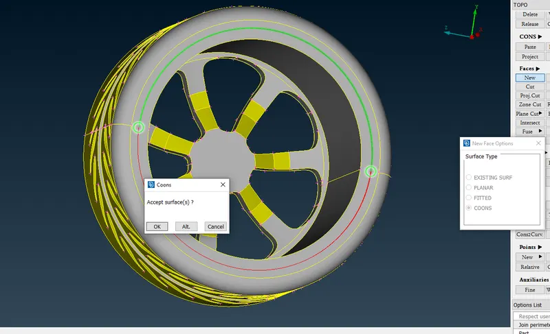
I generate the face as shown in the above image.
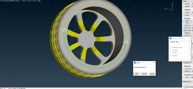
THe surface is generated using loop option.
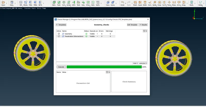
The geometry check for the rims and tyre show no error. Hence the errors are resolved.
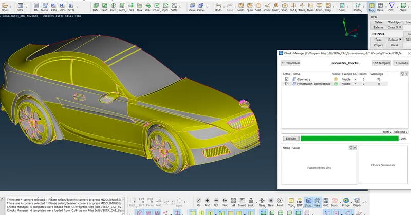
After that I do ALL and do the geometry check for the entire geometry and found no errors.
Hence the Geometry Clean up for the BMW car is done.
Now we assign the PIDs one by one as per given.
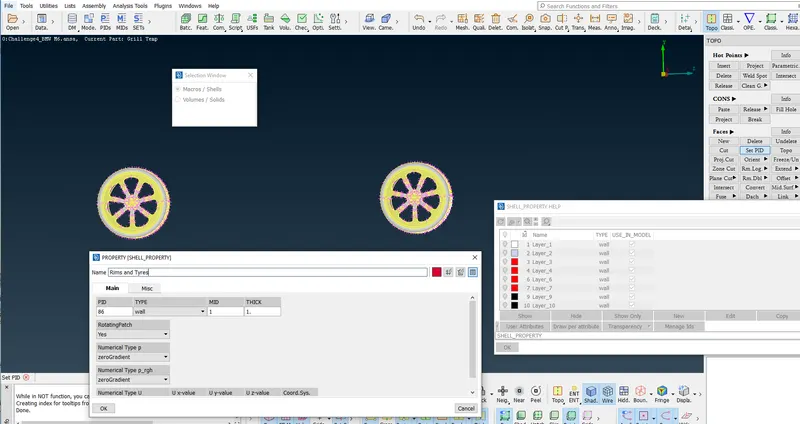
The above procedure is followed for assigning the PIDs.
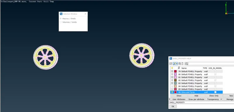
Rims and Tyres PID is assigned.
Similarly I will assign the PIDs for other parts.
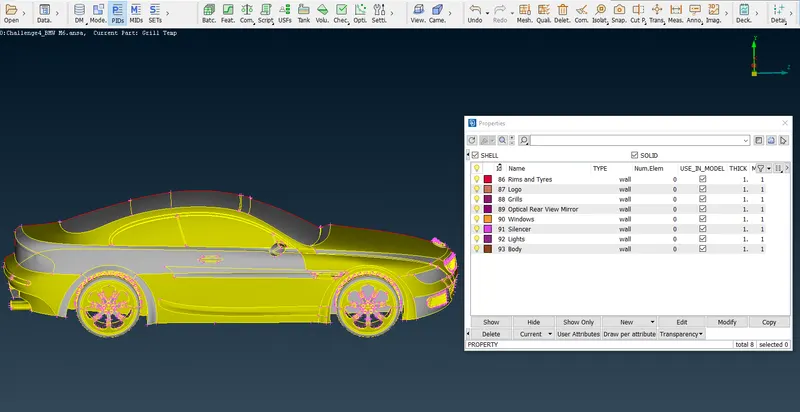
I have assign the PIDs as shown in the above image.
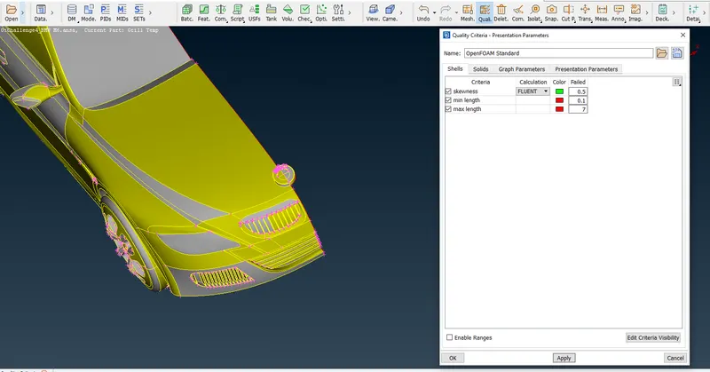
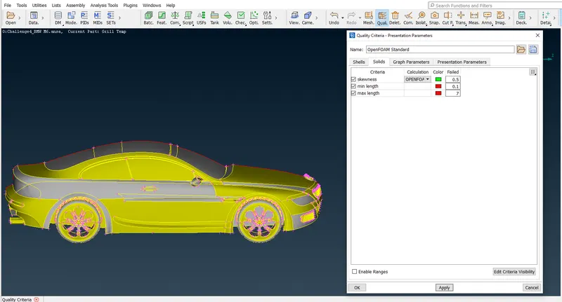
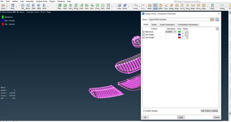
I assign the parameters for Quality Criteria (Given) as shown in the above image.
SURFACE MESHING OF GRILLS and LOGO
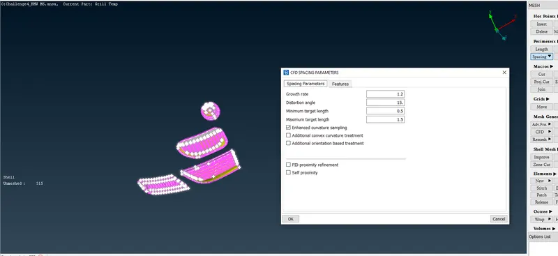
Using Auto CFD under Spacing under Parameters in TOPO I set the Target length of 1mm in the range of min 0.5 and max 1.5 (For Perimeters)
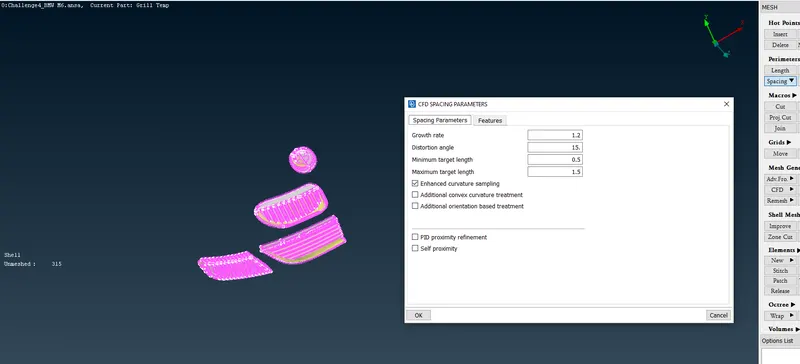
I set the Target length of 1mm in the range of min 0.5 and max 1.5 (For Macros). Using Visible under CFD under Mesh Generation the mesh is generated.
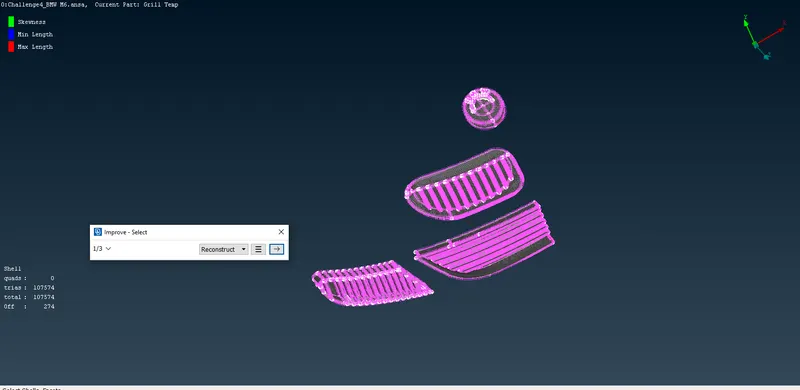
There were 274 off elements. Off elements are the elements that didn't satisfy the Quality Criteria Set.
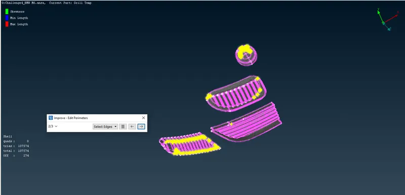
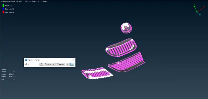
Using Reconstruct the off elements are reduced to 2.
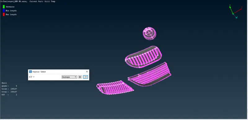
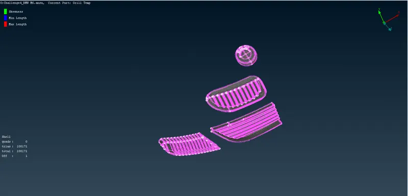
Now using Reshape the off elements are reduced to 1.
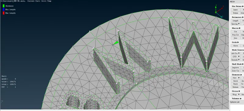
Green element near the M in logo had element that didn't satisfy the skewness.
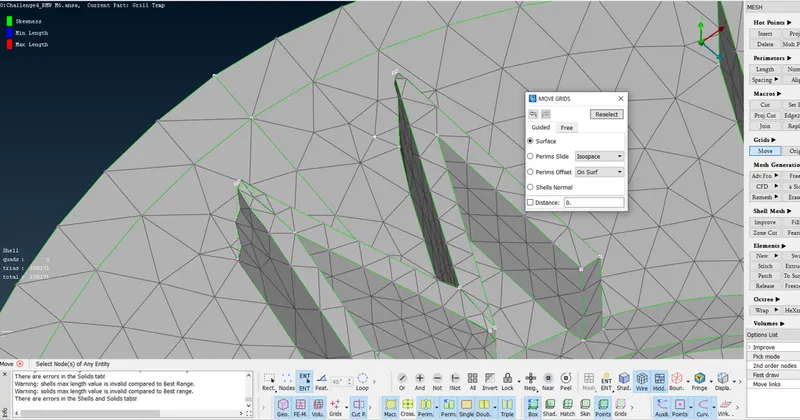
Using Move under grids we rectify the skewness of the elements and the all the off elements are resolved.
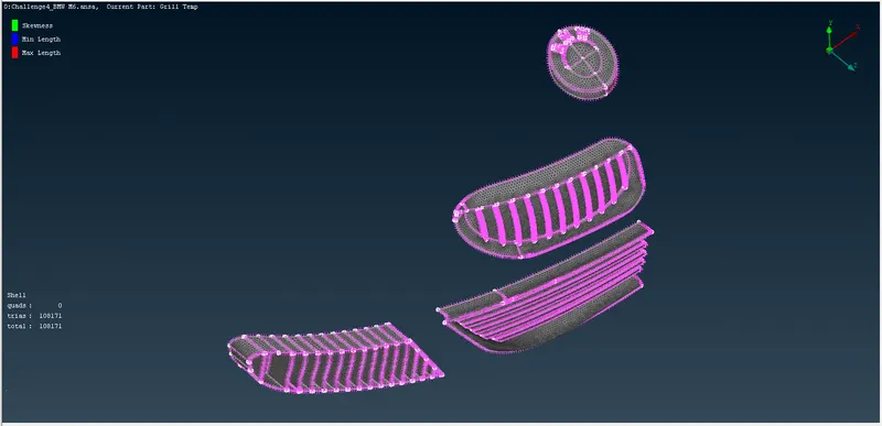
The surface meshing is done successfully.
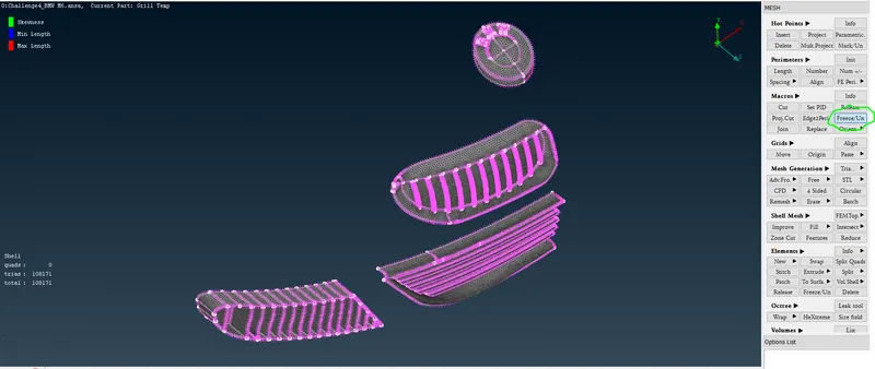
Finally we freeze the elements.
SURFACE MESHING OF Rims and Tyres, Windows, Optical Rear View Mirror
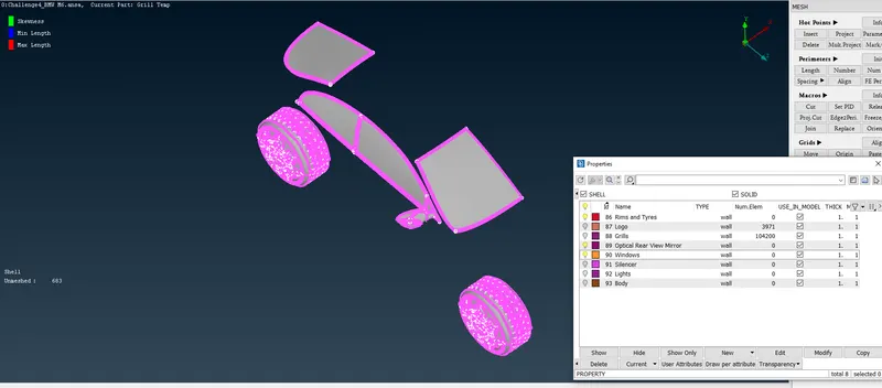
We isolate the parts using PID Manager
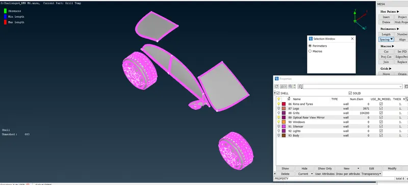
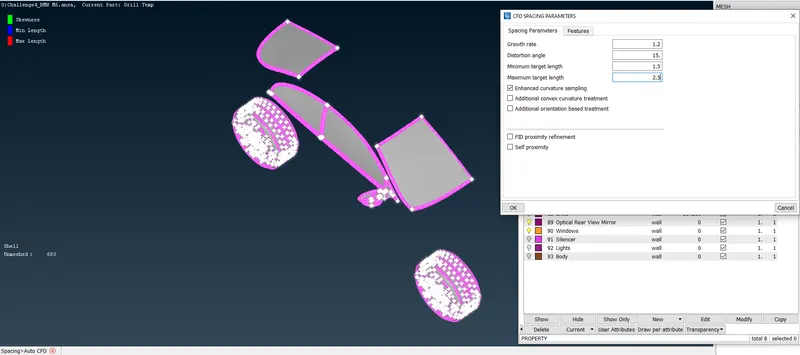
Using Auto CFD under Spacing under Parameters in TOPO I set the Target length of 2mm in the range of min 1.5 and max 2.5 (For Perimeters)
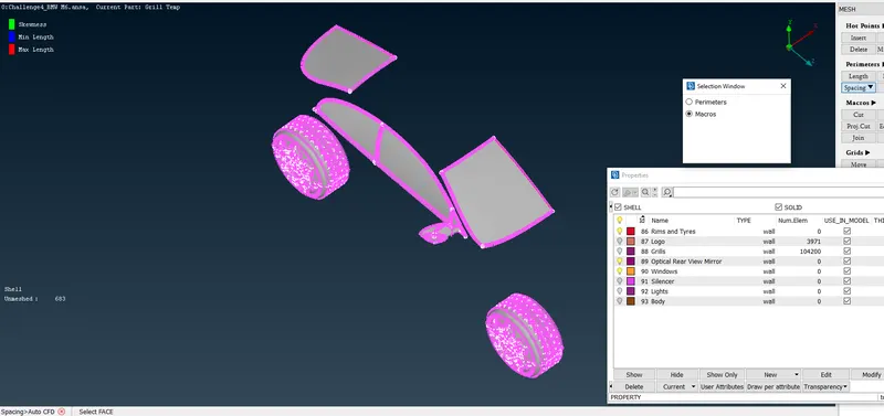
I set the Target length of 2mm in the range of min 1.5 and max 2.5 (For Macros)
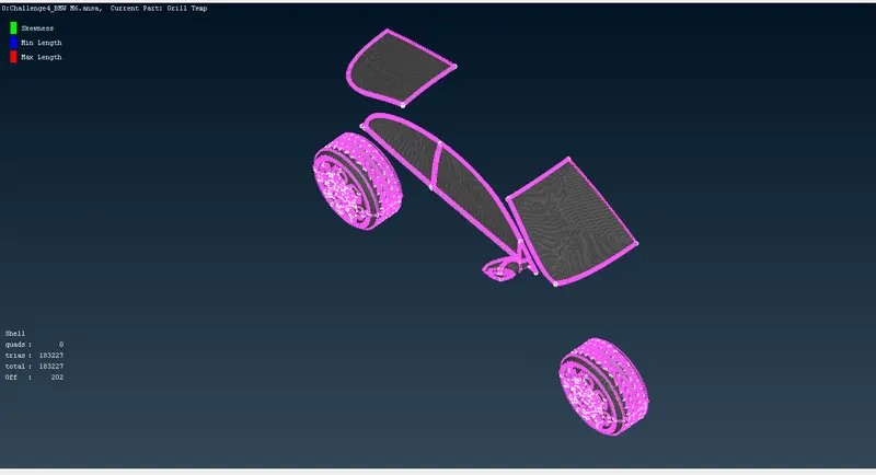
202 off elements were encountered.
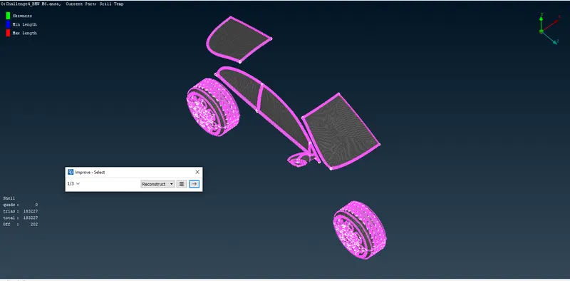
Using Reconstruct as shown in the above image we try to eleimnate the off elements.
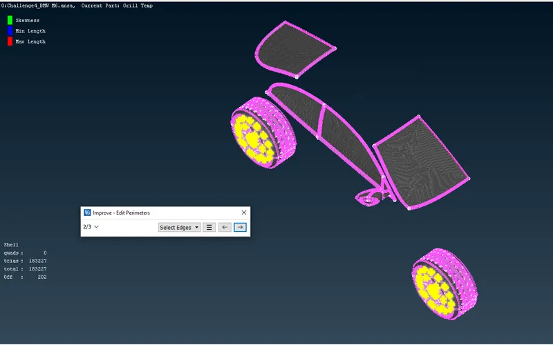
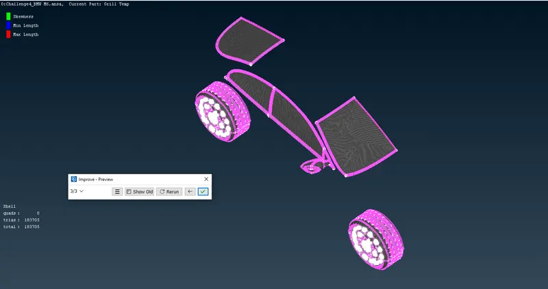
Off elements are taken care off. No more off elements found.
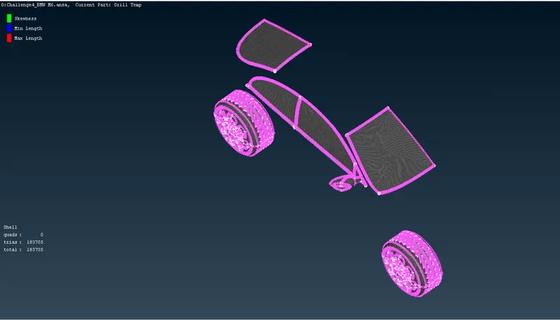
The surface meshing of windows, mirror and tyres along with the rims is done sucessfully.
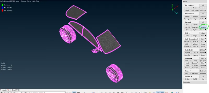
Finally we freeze the elements.
SURFACE MESHING of Silencer
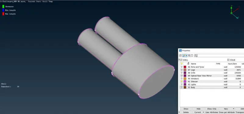
Now the silencer is isolated for surface meshing
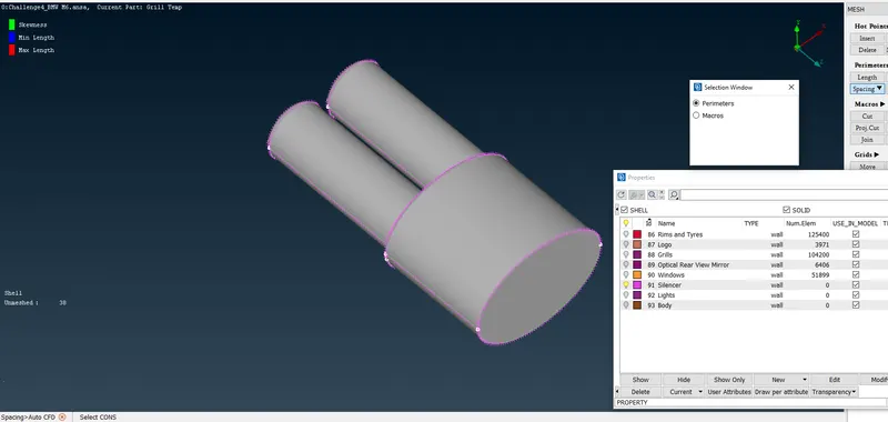
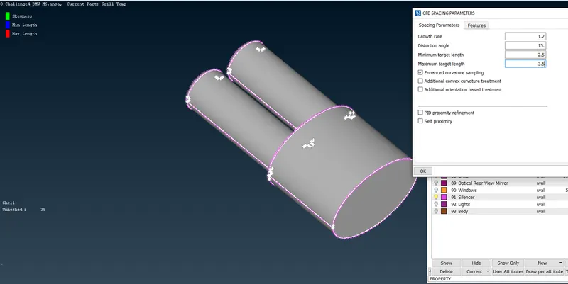
Using Auto CFD under Spacing under Parameters in TOPO I set the Target length of 3mm in the range of min 2.5 and max 3.5 (For Perimeters)
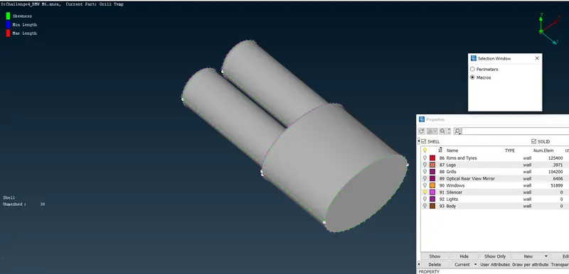
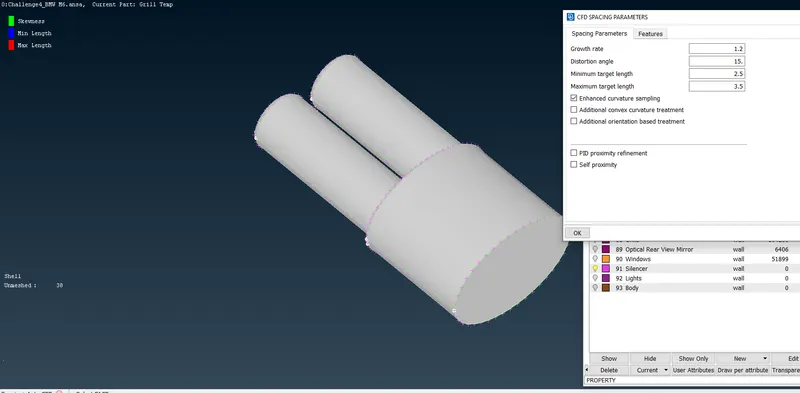
I set the Target length of 3mm in the range of min 2.5 and max 3.5 (For Macros)
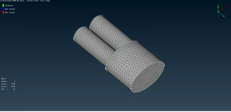
After Meshing 41 off elements were found.
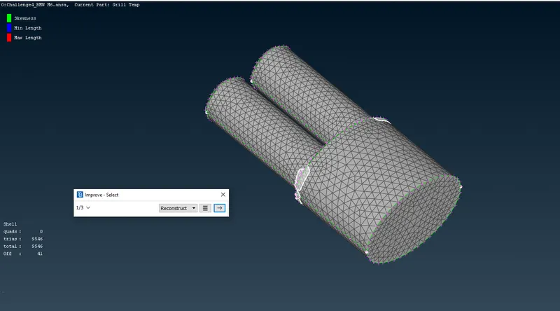
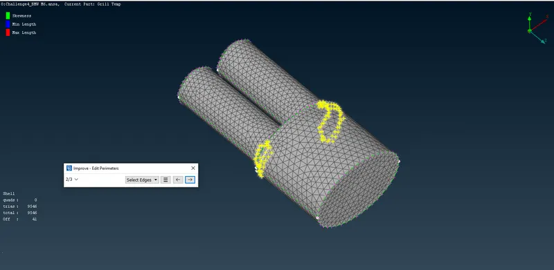
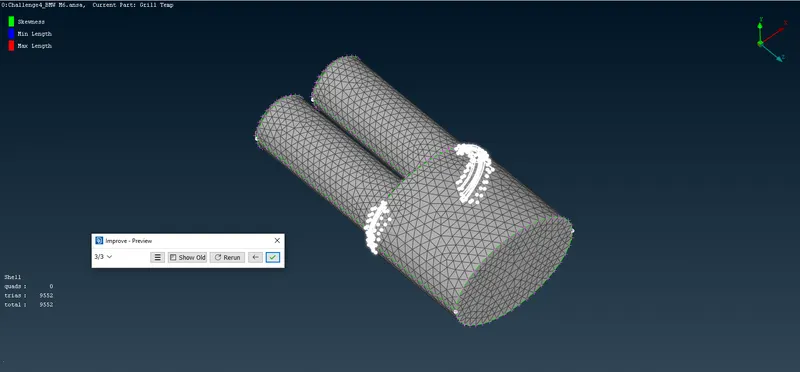
After using reconstruct all the off elements were resolved.
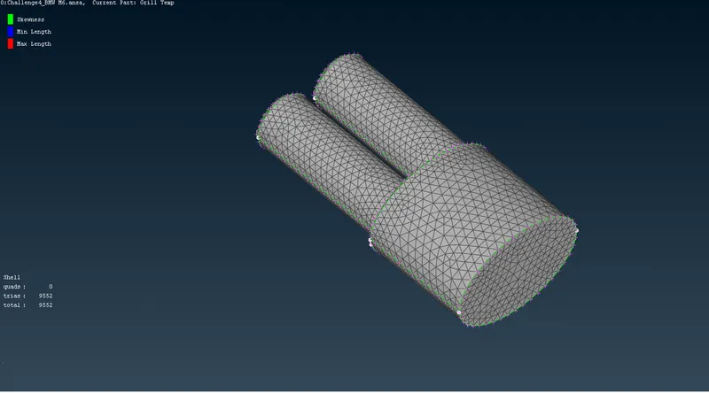
Surface meshing of the silencer is done.
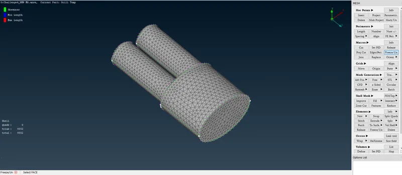
Finally we freeze the elements.
SURFACE MESHING of Body
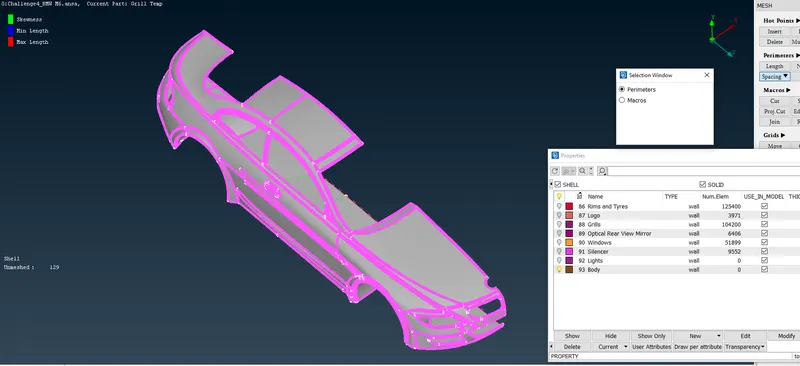
We isolate the Body of the car using PID Manager.
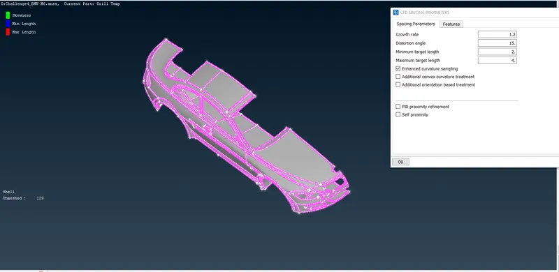
Using Auto CFD under Spacing under Parameters in TOPO, I set the Target length of 3mm in the range of min 2 and max 4 (For Perimeters)
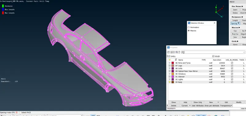
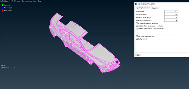
I set the Target length of 3mm in the range of min 2 and max 4 (For Macros)
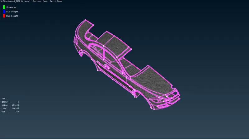
After surface meshing, 329 off elements were found.
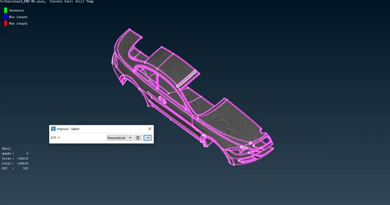
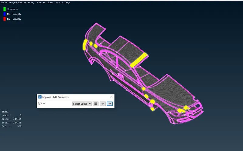
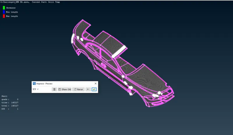
Using Reconstruct 329 off elements were reduced to one.
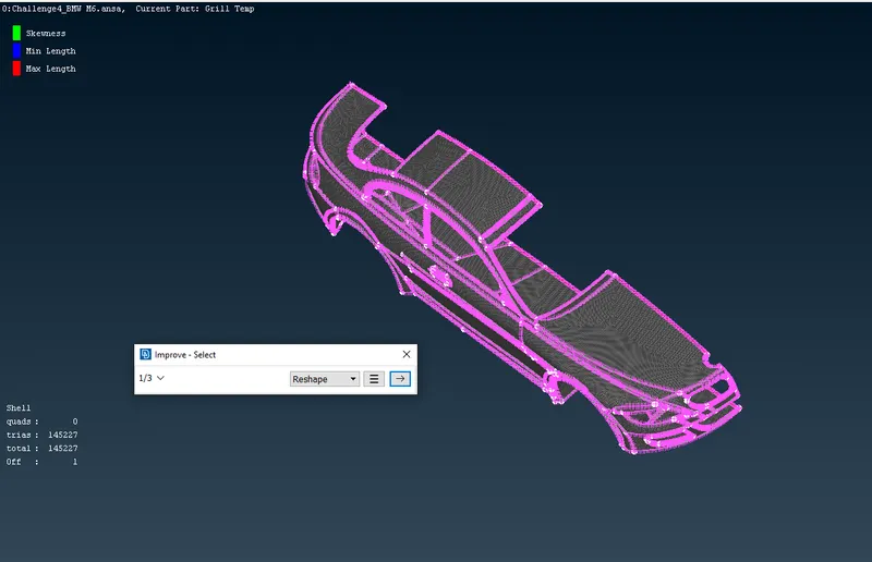
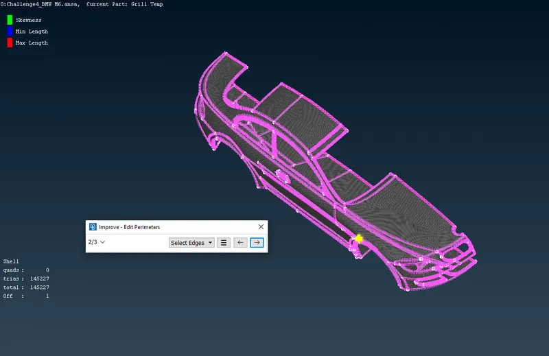
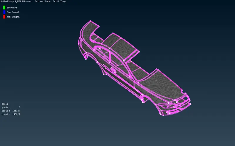
Using Reshape 1 off element was rectified. Finally the surface meshing of the Body is done.
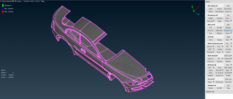
We freeze the elements.
SURFACE MESHING of Lights
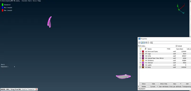
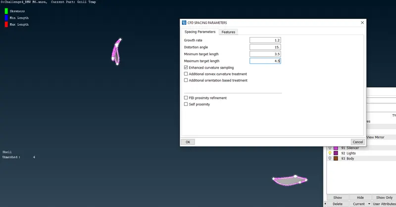
Using Auto CFD under Spacing under Parameters in TOPO, I set the Target length of 4mm in the range of min 3.5 and max 4.5 (For Perimeters)
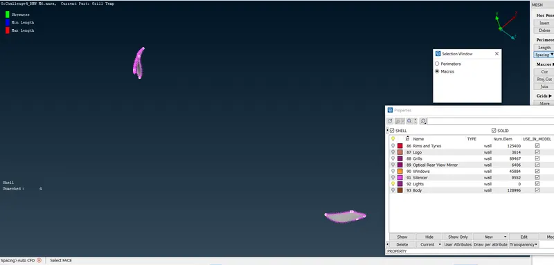
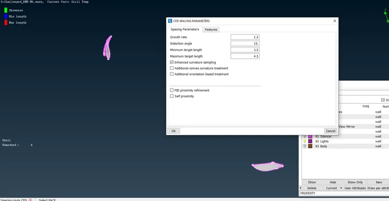
I set the Target length of 4mm in the range of min 3.5 and max 4.5 (For Macros)
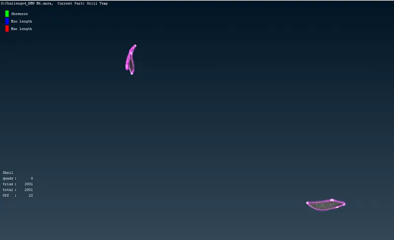
22 off elements were encountered.
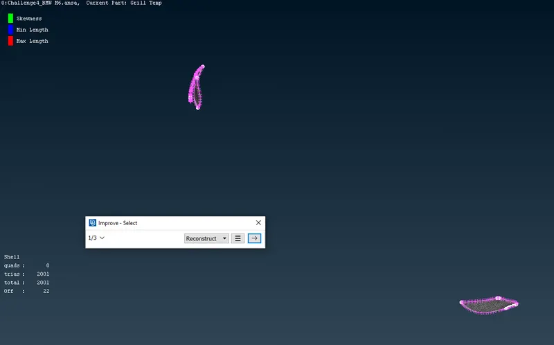
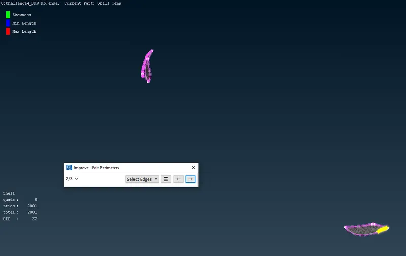
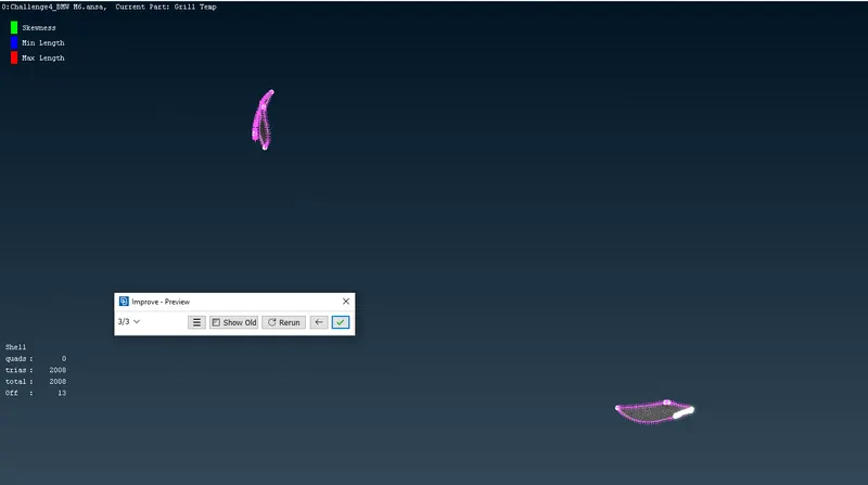
Using Reconstruct 22 off elements were reduce to 13.
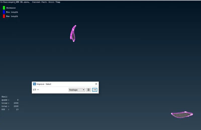
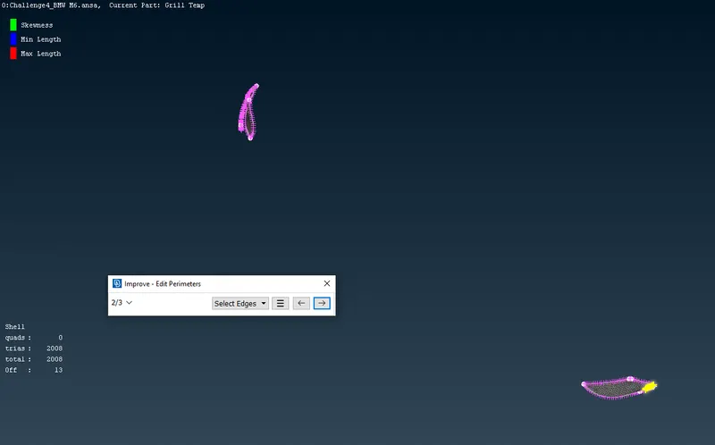
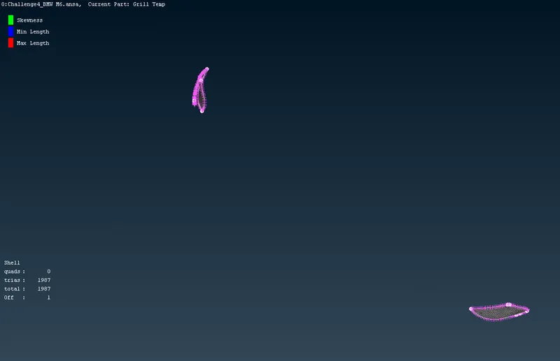
Using Reshape 13 elements were reduced to 1.
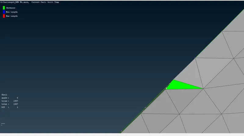
THe 1 off element was failing the criteria of Skewness.
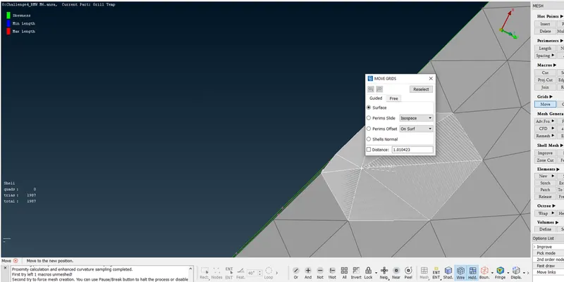
Using Move under Grids we resolve the off element as shown in the above image.
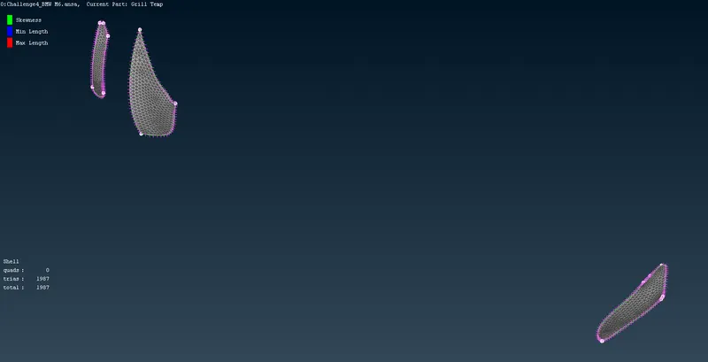
Surface meshing of the lights is done.
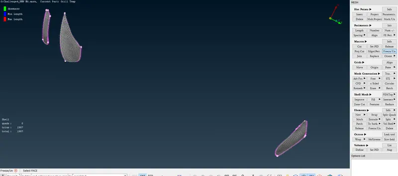
Finally we freeze the elements.
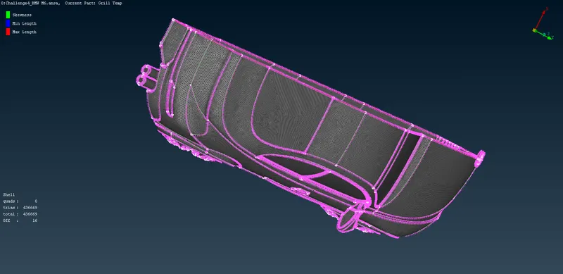
After doing All 16 off elements were found.
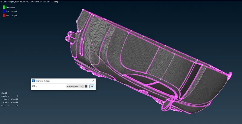
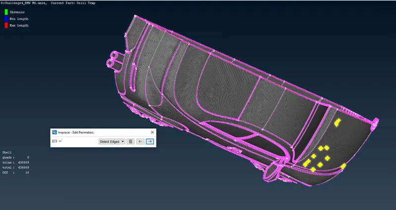
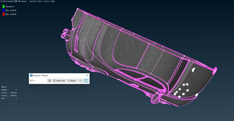
Using Reconstruct 16 off elements were reduced to 1.
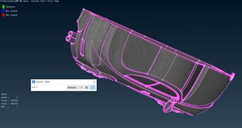
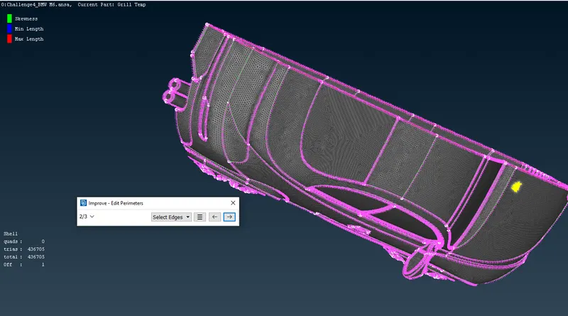
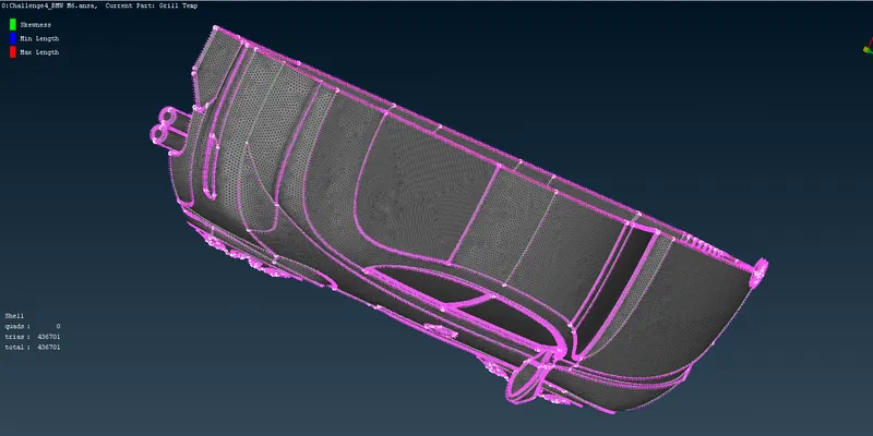
Using Reshape 1 off element is resolved. Finally the surface meshing of the half part is done. We freeze the elements.
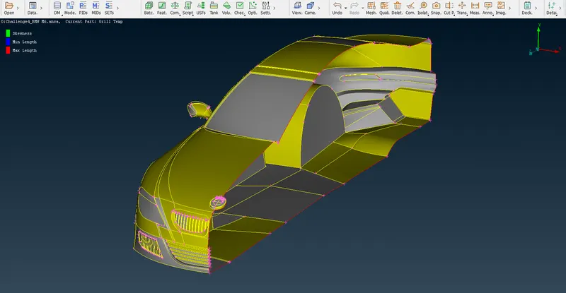
Now we will create the other half of the BMW car.
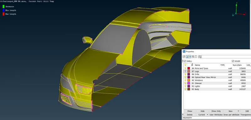
Using PID Manager we hide the Logo.
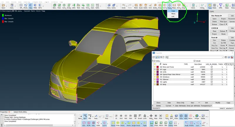
Using Copy under Transform, we create the copy of the half portion of the body.
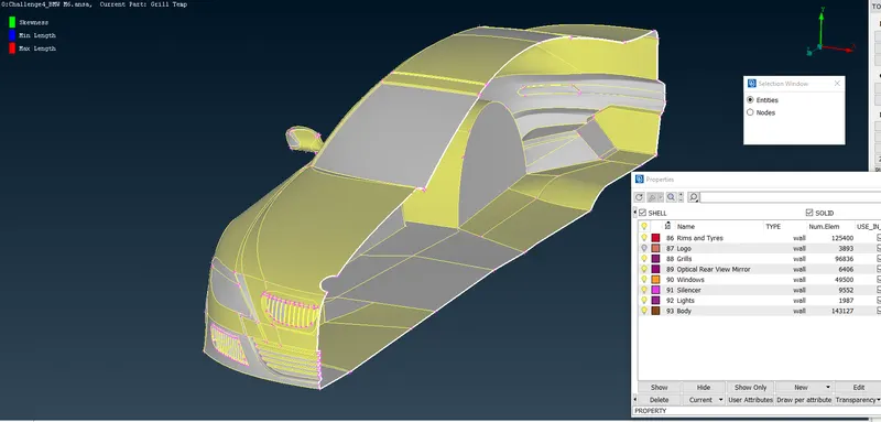
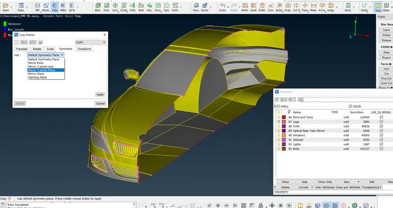
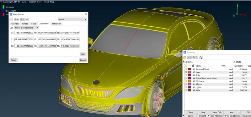
Click Finish and the copy is done. Total 3 red cons appear after copy operation is done.
Using TOPO the Red cons near the Logo was resolved.
Using Merge Faces we resolve the red cons present on the window.
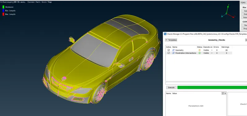
The geometry check is carried out using Checks Manager and no errors were found.
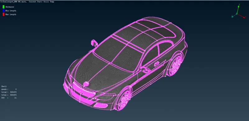
Now surface meshing is performed on the entire car, 21 off elements were found.
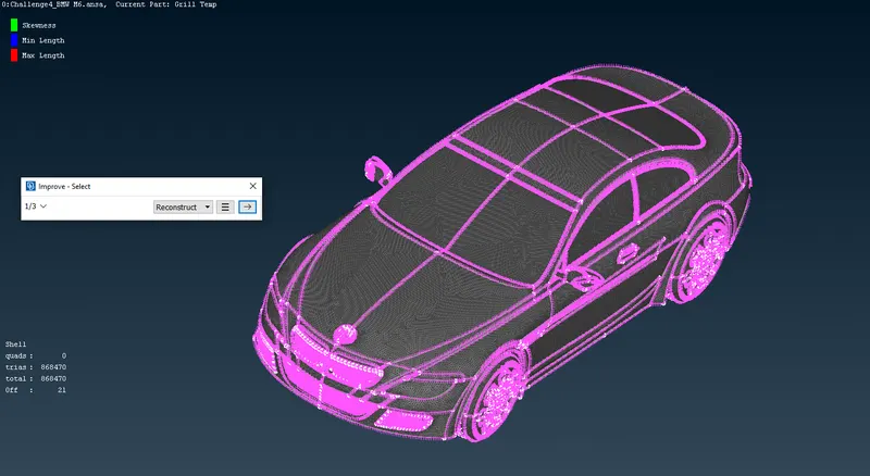
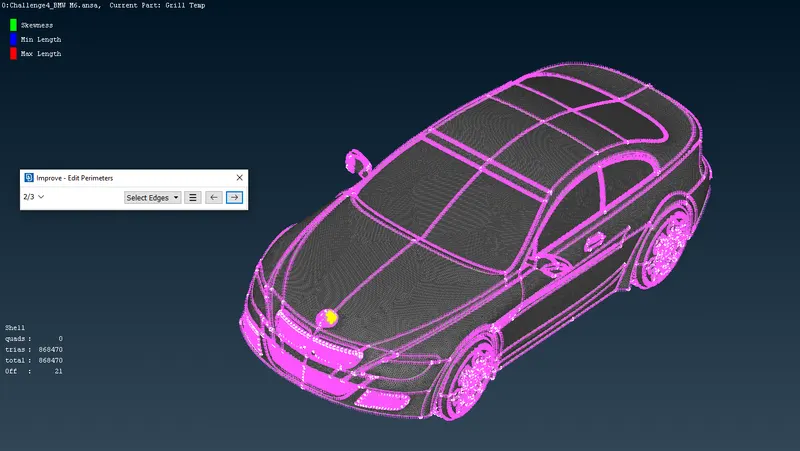
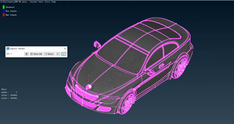
Using Reconstruct 21 off elements were resolved.
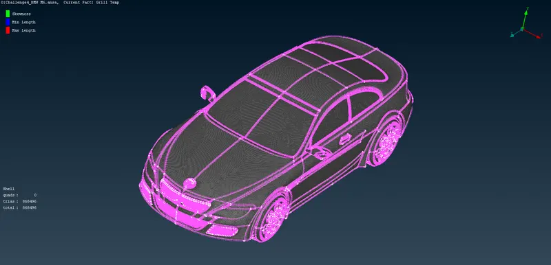
Finally the surface meshing of the BMW car is completed.
I am done with meshing now I need to create wind tunnel with given parameters now.
WIND TUNNEL CREATION AND MESHING
The parameters are as follows-
- 4x from front of the car
- 6x from rear of the car
- 3x from top of the car
- Bottom close proximity with tyres
- 1x from the centre plane for left and right sides
Where x = length of the car which comes out to be approx. 1310 mm for the given model.
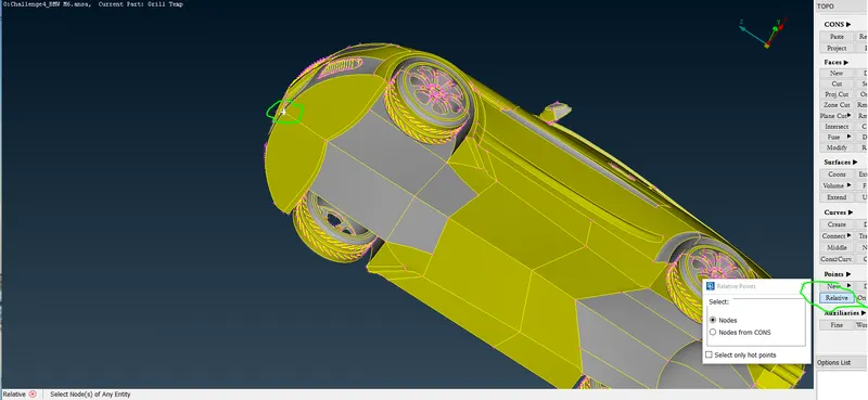
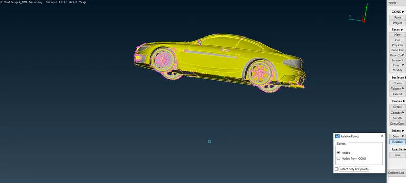
We generate points using the option shown in the above image.
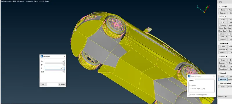
The distance was estimated using Measure.
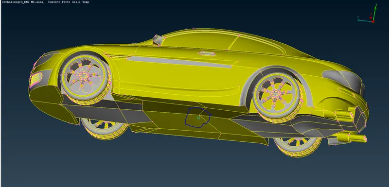
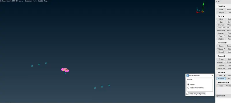
A point is created. Now using this point we create the other points
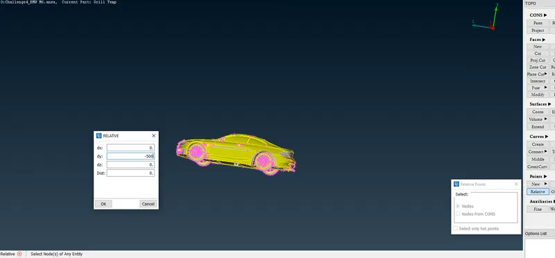
This distance is just a random selection in order to avoid the tyre intersection with bottom surface of the wind tunnel.
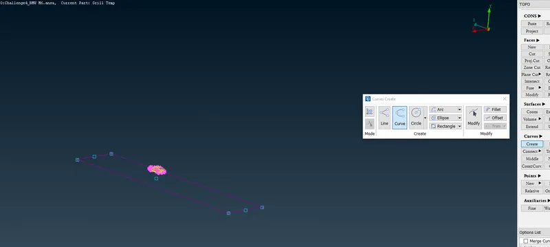
Now a curve is created using the points generated.
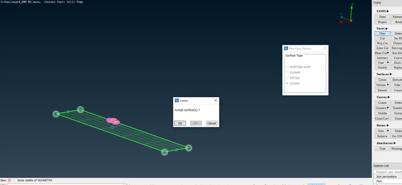
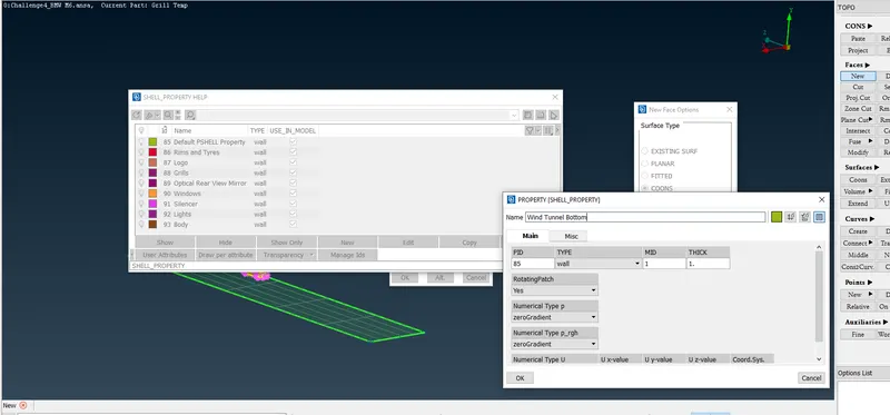
wind tunnel surface is created and a New PID is assigned to it.
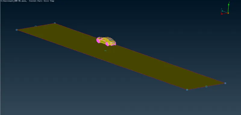
Wind tunnel bottom surface is created
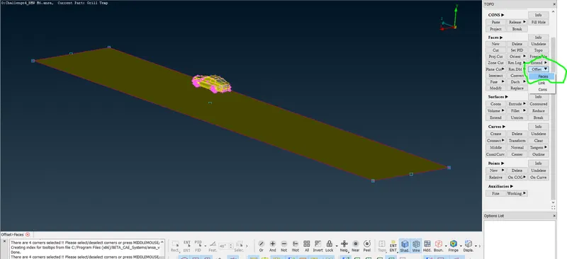
Using an Faces under Offset in Face of TOPO we create a TOP face of the wind tunnel.
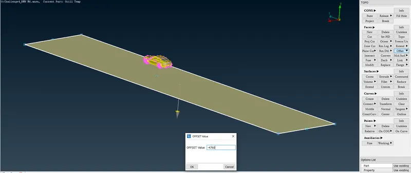
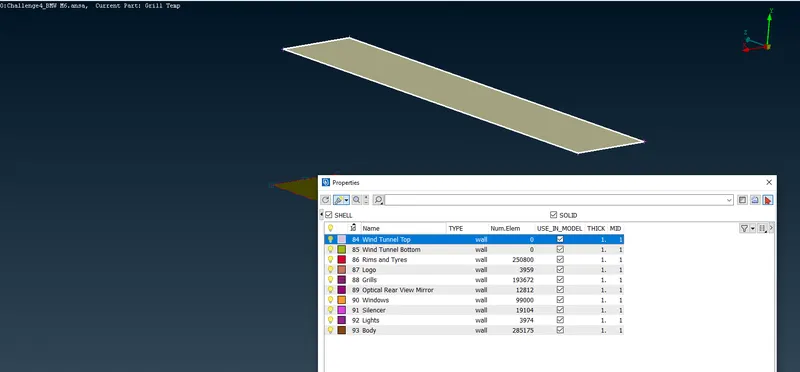
Wind tunnel Top surface is created and a PID is assigned to it.
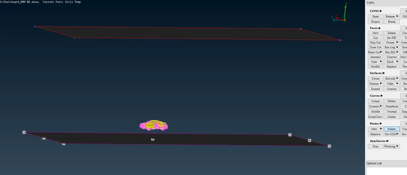
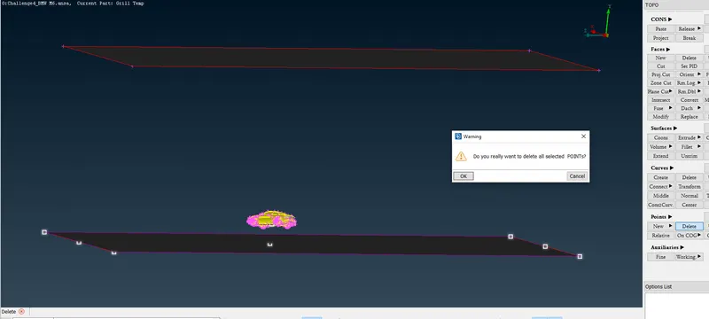
Now the selected points are deleted.
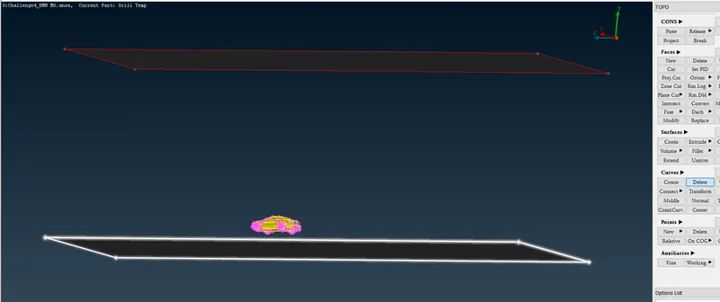
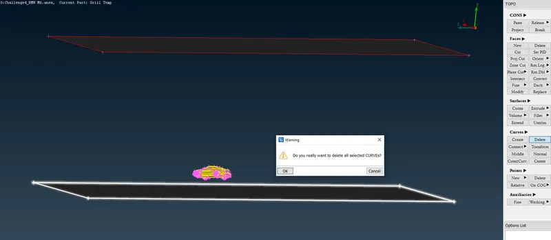
Curves created are deleted.
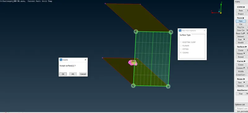
The back surface of the wind tunnel is created.
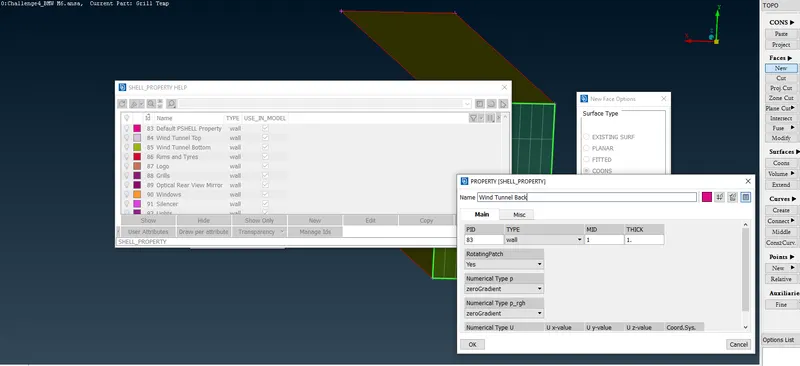
A PID is assigned to the back surface of the wind tunnel.
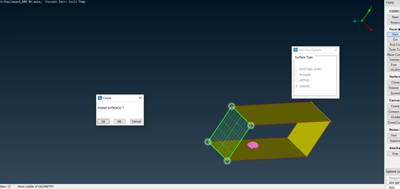
Front surface of the wind tunnel is created.
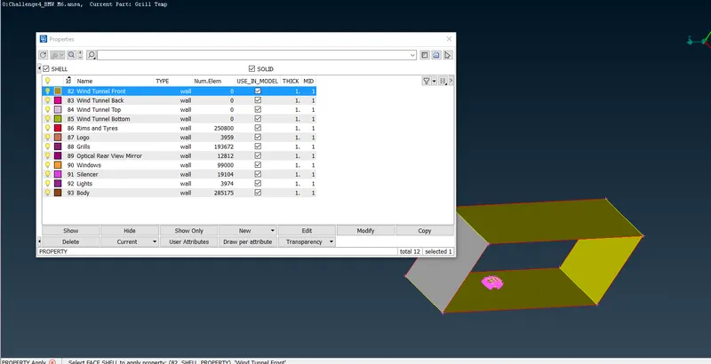
A PID is assigned to front surface of the wind tunnel
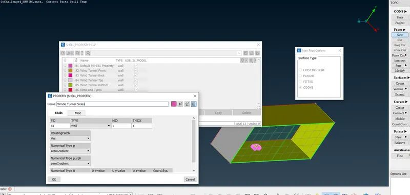
Side surface of the wind tunnel is created and PID is assigned to it
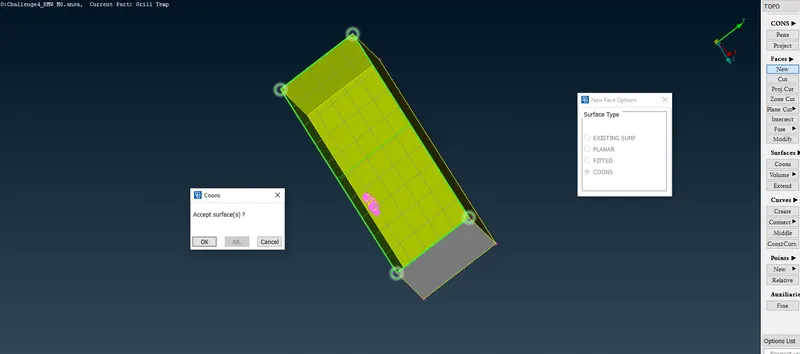
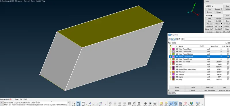
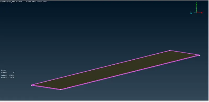
Surface Meshing of the bottom surface is done.
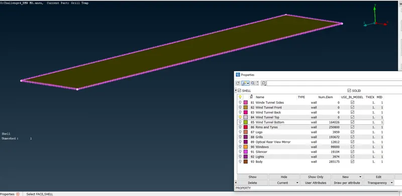
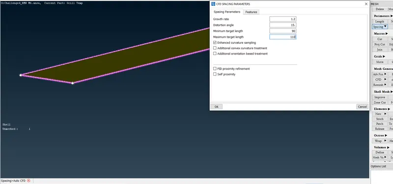
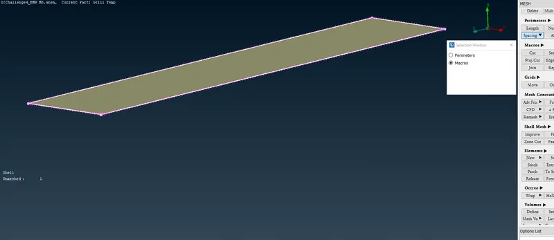
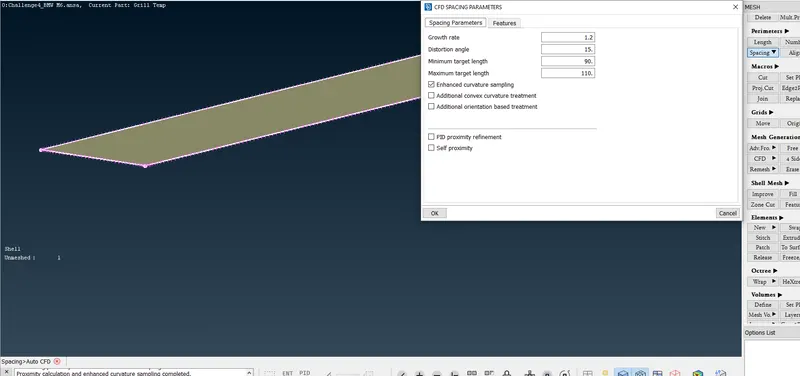
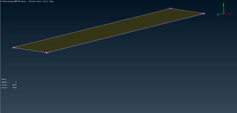
Surface Meshing of the top surface of the wind tunnel is done.
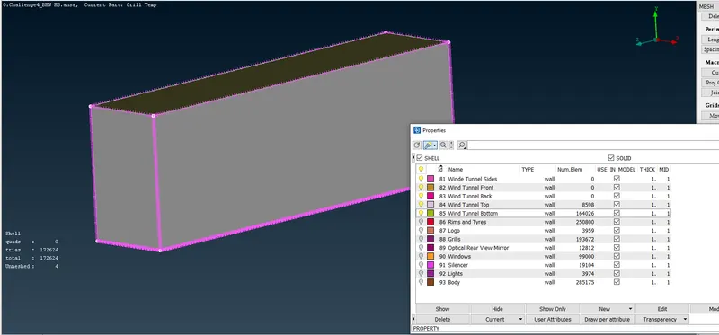
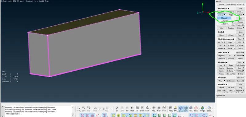
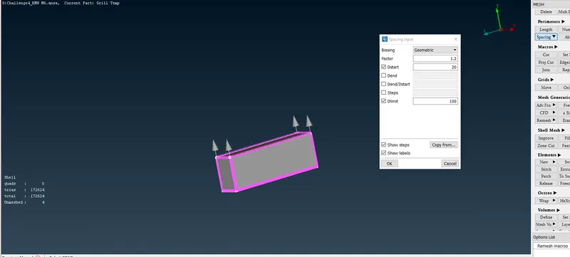
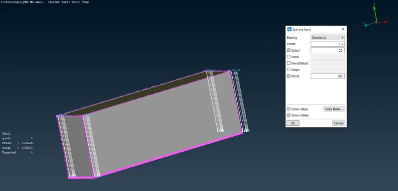
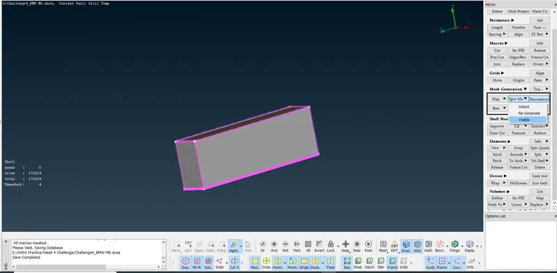
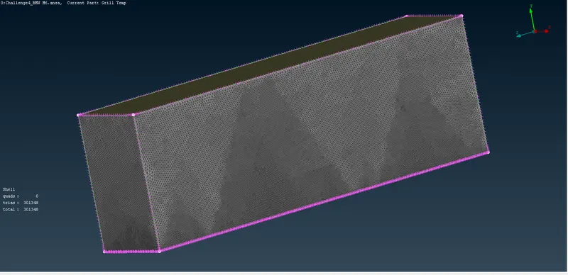
Surface Meshing of the wind tunnel is done.
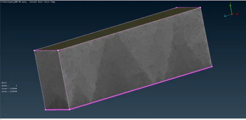
After doing All no off elements or Unmeshed surface were found.
Hence we conclude that surface Meshing of the BMW ca is done along with Wind Tunnel creation and it's Surface Meshing.
To view Challenge4_BMW M6 - After Geometry Cleanup.ansa file click below link
https://drive.google.com/file/d/1b4-96uzhfyszVU7PPPymtXX9c5odYDQ2/view?usp=sharing
To view Challenge4_BMW M6 - After Surface Meshing.ansa file click below link
https://drive.google.com/file/d/1bVJ4v4Qb_ytyPZqWvHfy6AjM_qB9FwYf/view?usp=sharing
To view Challenge4_BMW M6 - Final after Wind Tunnel Surface Meshing.ansa file click below link
https://drive.google.com/file/d/15imIWbYPFZZVV_reJ5DzQRCe_wRpdUz6/view?usp=sharing
Conclusion:
- Geometry clean up of BMW is done.
- Surface Meshing of BMW with Quality Criteria is done.
- Wind Tunnel creation is done.
- Surface Meshing of Wind Tunnel is done.