Geometry preparation and Meshing of automotive body for aerodynamic analysis using ANSA.
OBJECTIVE
Perform geometrical cleanup after performing geometry check for multiple checks & rectify them to ensure a close surface for performing a CFD meshing using specified element size. The nature of the element shape should be TRIA element.
TOOLS USED:
- FILL HOLE
- HOT POINTS(INSERT)
- TRANSFORM(SYMMETRY)
- TOPO
- CONS(PROJECT)
- CONS(RELEASE)
- FACES(EXTEND)
- DELETE
- FACE(FITTED)
- FACE(PLANAR)
- FACES(CUT)
- FACES(OFFSET)
- FACES(ORIENT)
- CURVES(CREATE)
- CURVES(DELETE)
- CURVES(CONS2CURVE)
- AUXILIARIES(FINE)
- PERIMETER(LENGTH AND MACROS)
- PERIMETER(SPACING)
- MESH GENERATION(ERASE)
- ELEMENTS(SPLIT)
- GRIDS(MOVE)
- GRIDS(PASTE)
- SPOT MESH
- CFD MESH
- UNFREEZE
- V MESH( VOLUME=>DEFINE)
- VOLUMES(LIST)
PROCEDURE:
- As this is a geometry for external airflow simulations all unnecessary surfaces would be deleted inside geometry.
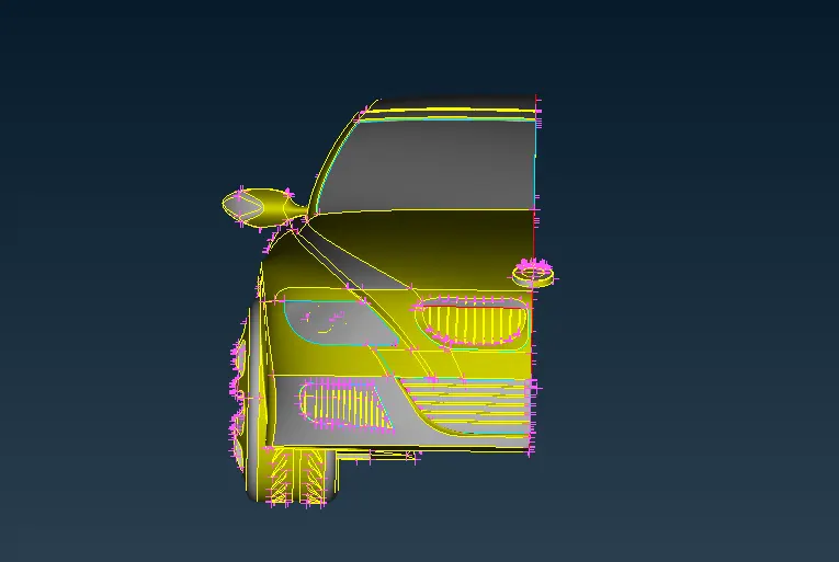
- While opening up ANSA geometry is visible as shown below. PIDs are not assigned properly.
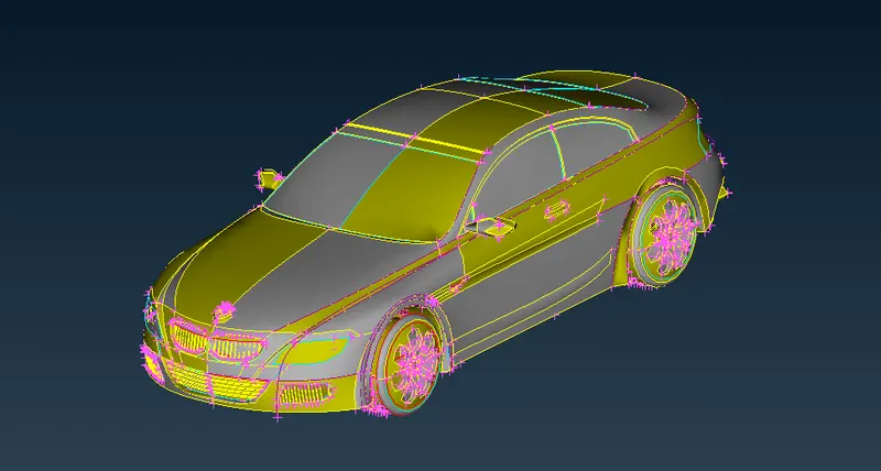
- Hide all double cons(yellow). The following geometry is displayed as mentioned below. By visually inspecting the given figure it can be hypothesized that geometry consists of triple cons and red cons.
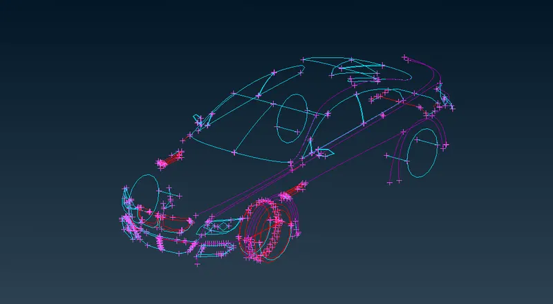
- Initially, geometry is appearing distorted due to the lower resolution. Keep resolution between 0.1-1 for better and more accurate curvature and geometry details. Use Classic mesh--> Length--> Perimeters--> Box select full geometry--> middle click--> give length perimeters as 0.1--> OK.
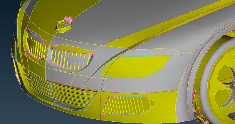
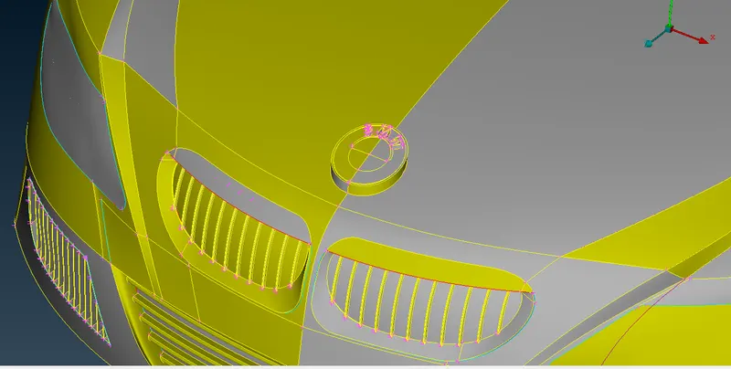
- After changing the resolution, the geometry is visible properly. Running diagnosis in the checks manager it can be concluded that geometry consists of 243 errors and 58 intersections. The first step of proceeding with the car models taking care of the geometrical error of the entire car which would be a tedious process for solving the entire car model.

- As a solution to this, Due to the symmetrical property of geometry, half part of the geometry can be deleted and all the geometry repair and mesh operations can be performed with the remaining geometry. After completion, the symmetrical part would be mirror copied.
- Faces---> Box Select the faces--> Delete a symmetrical part except logo.
--------------------------------------------------------------------------------------------------------------------------
GRILL DELANTERO
- Starting with grills, the lower middle grill was selected and isolated for CAD cleanup. This grill is known as grill delantero.
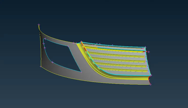
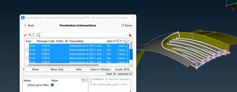
- Intersections were repaired using Intersect tool and Project cons and face cut options were used to repair other parts. Unecessary internal surfaces were deleted.
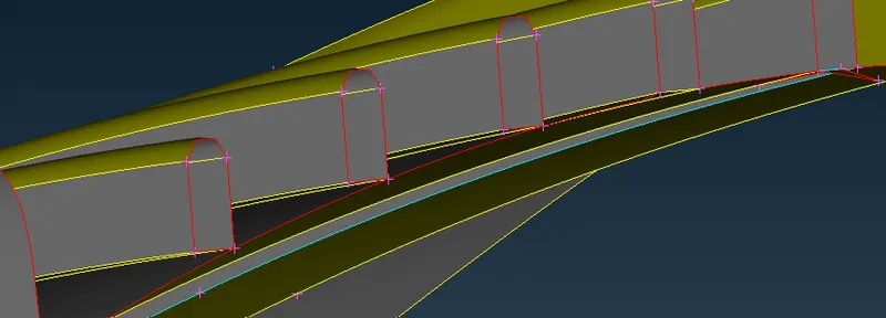
- This misalignment in grills is treated using project surface option, then furthur extended features were done using surface--> cut option. Extra surfaces were deleted.
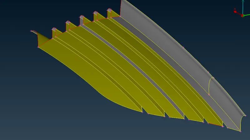
- Pre-processing of grill delantero is completed.
------------------------------------------------------------------------------------------------------------------
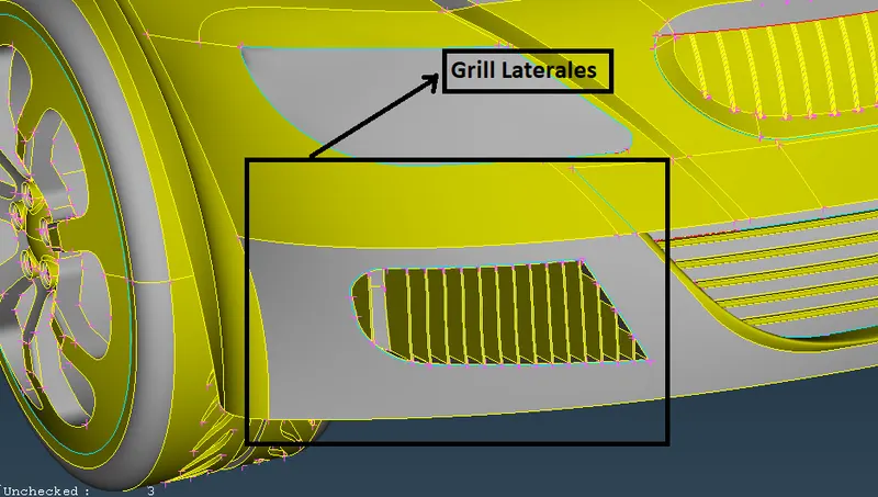
GRILL LATERALES
- After this grill, grill from lower bottom corner was identified, this grill is known as grill laterales. This grill was isolated and repaired.
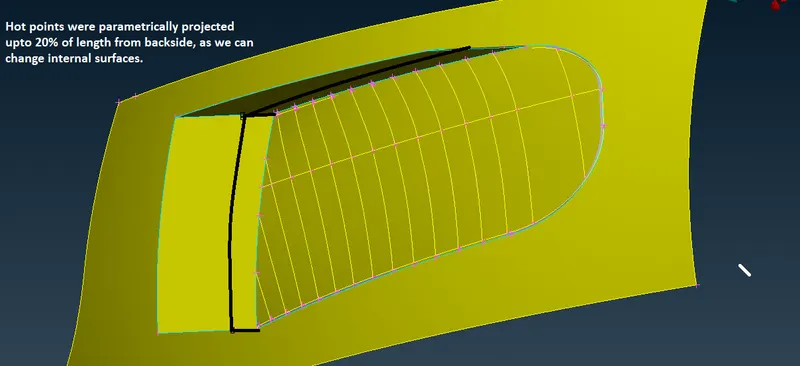
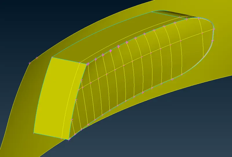
- Hot points were projected from back and a cut is done. After the face cuts a surface was created using Coons option. After New surface formation, a new PID was assigned to new surface and by using surface option 20% of external surfaces were deleted.
|
Hot point parametric projection. |
 |
|
Cutting of faces using projected hot points with faces--> Cut option. |
 |
| Make a new surface using fitted algorithm and do a TOPO. Assign this surface to a new PID. | 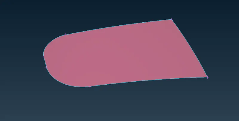 |
| Use intersection option to separate these surfaces and delete the backside 20% portion. | 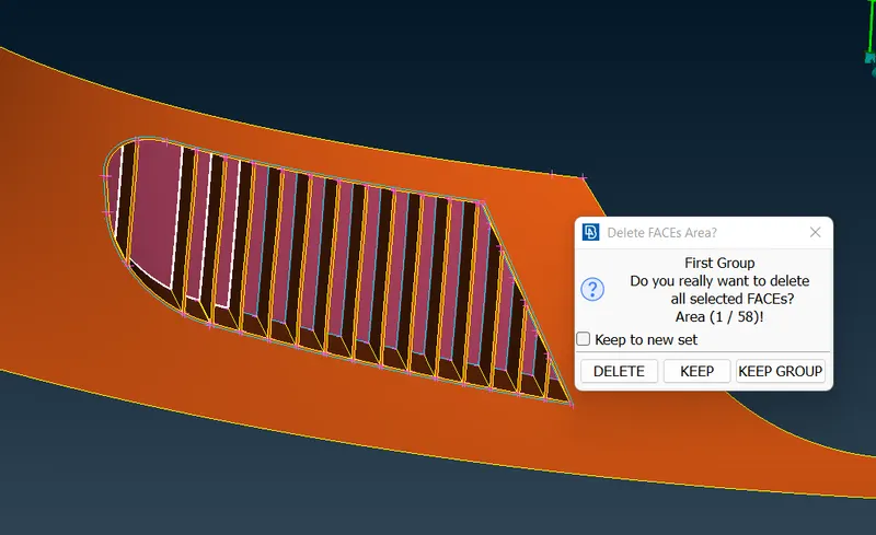 |
| Finished grill Laterales. | 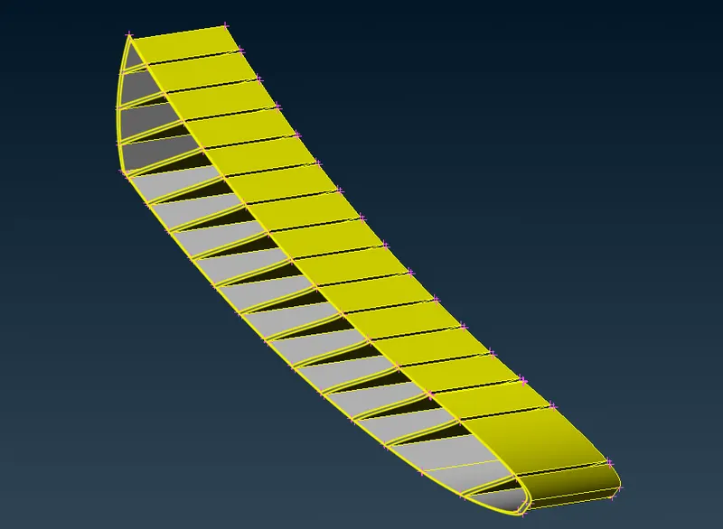 |
----------------------------------------------------------------------------------------------------------------
FRONT GRILLS
- Front grill was isolated using NOT option and LOCK option was used to hull screen condition. Front grey part is coming in front of the grill bars, due to this grill bars and surface parts which are hidden by grey surface were deleted. Detailed eplaination for pre-processing is described in detail.
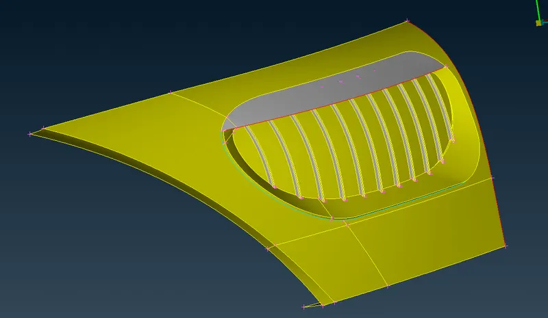
Detailed explaination for pre-processing is described below.
| Highlighted face conflicted with some surfaces and geometries therefore it was deleted. Surfaces with Blue/Triple cons were also deleted. | 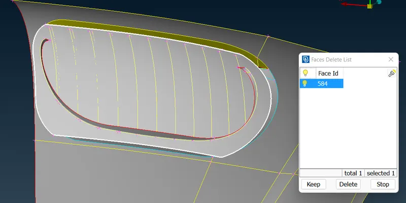 |
| Backside surfaces of grill-bars were deleted because they would have been considered as Closed volumes by ANSA while applying Volume Meshing. | 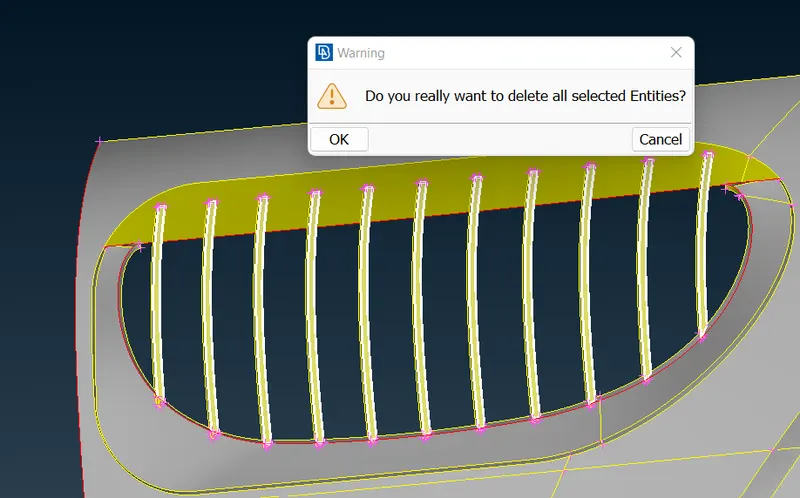 |
| In this figure, it can be seen that grill bars are sheared/distorted about the base surface, as a rework face cut were made on each and every grill except grills at the end. Distoted surface was deleted. | 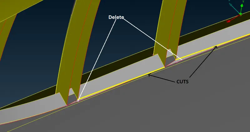 |
| New surfaces were created between each pair of grills, due to gap. These surface will stop the air at the body only, otherwise air would flow inside the BMW volume. | 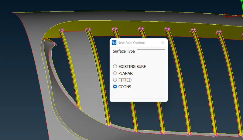 |
| Hide all extra surfaces except front surface of grills and backside. Use Hotpoints--> Insert to add a hot point at mid of upper grey surface of grill. This hot point would be used to plane cut the backside surfaces with the reference of front surface. | 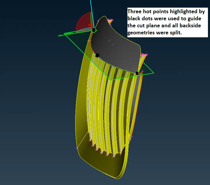 |
|
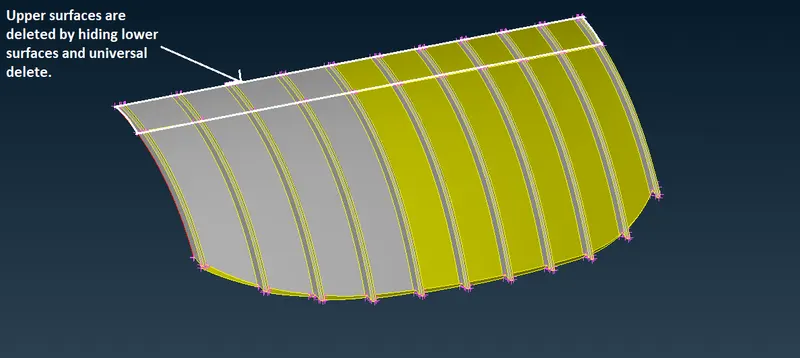
Highlighted surfaces were deleted. Lower surface was hidden using NOT option. Note: These highlight is just for visual representation. |
 |
|
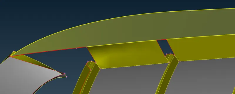
Hot points are inserted at grill surface to join the gap between top surface and top of grill bars. First bigger parts were created and then remaining grill-bar curvature parts were joined. Do this for each part. |
 |
|
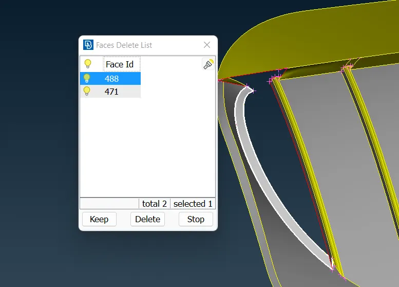
For Intersecting geometry Delete and Patch surfaces part by part as needed. At the end there must be no intersection errors left. |
 |
No Errors and warnings were present with no intersections and errors.
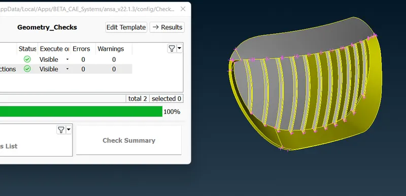
----------------------------------------------------------------------------------------------------------------
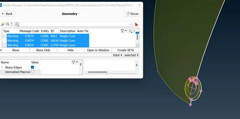
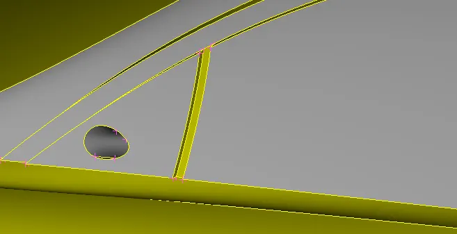
Now as major parts errors are finished we will carry with minor parts such as LOGO, Headlamps, Indicators,
Inside parts of headlamp would not be the part of CFD analysis therefore inside surfaces were deleted.
| PART | BEFORE | AFTER |
| Headlamp | 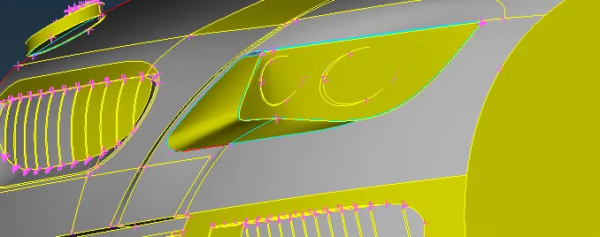 |
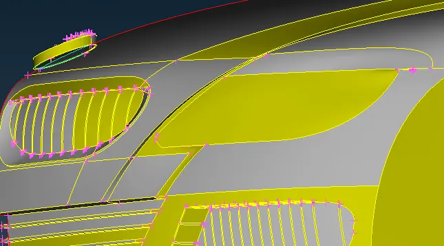 |
| Logo | 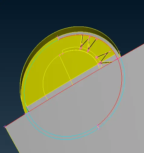 |
 |
| Optical rear-view mirror. | 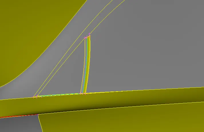 |
 |
| Silencer | 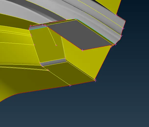 |
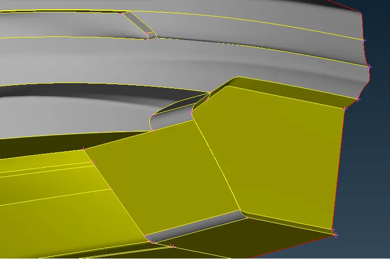 |
| External | 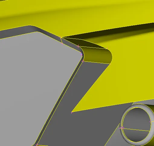 |
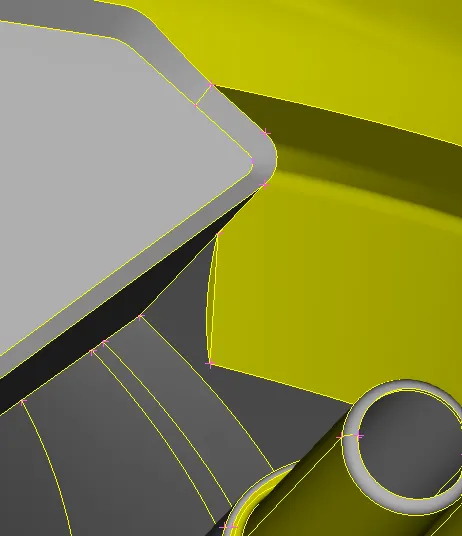 |
----------------------------------------------------------------------------------------------------------------
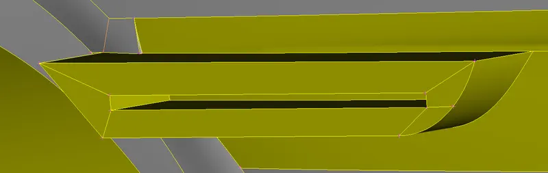
INDICATOR
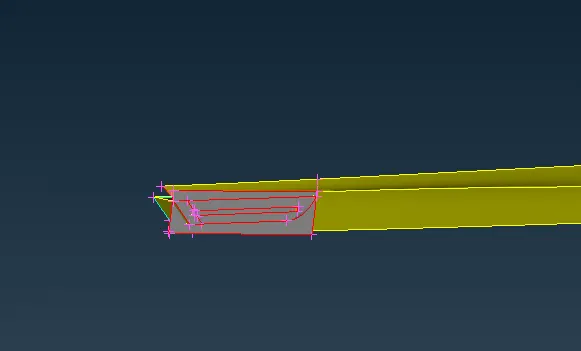
Indicator intersection errors were cleared and geometry was prepared for required airflow analysis.
| Deleting this surface from backside which was causing intersection errors. | 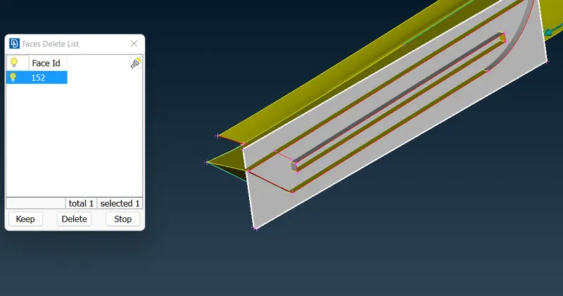 |
|
Deleted some more surfaces to clear all single and triple coons. Patched inside surface with faces--> New--> Coons option. |
 |
----------------------------------------------------------------------------------------------------------------
FLOOR CLEANUP
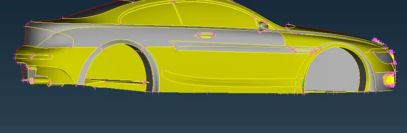
| Before starting clean-up use cons2curve tool to make overlapping curves on edges which will be utilised for reforming of similar surfaces after cleanup. | 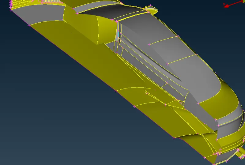 |
|
Delete the intersecting surfaces which were intersecting with wheels and lower body of cars. Extra surfaces were deleted which were present inside of body. |
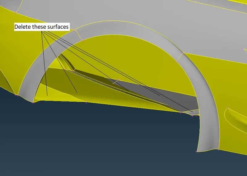 |
|
These geometries were not deleted completely due to their complex curvature. Instead intersection option was used to create boundary and then delete the intersecting surfaces. |
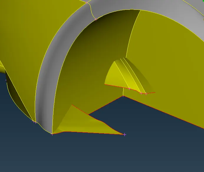 |
| Delete the highlighted surfaces from front side. | 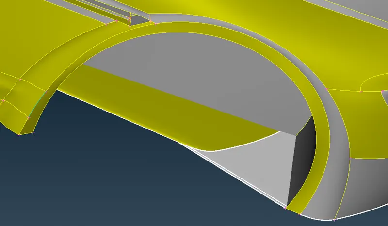 |
| Removed almost all intersecting parts except the complex geometries which were difficult to amend. | 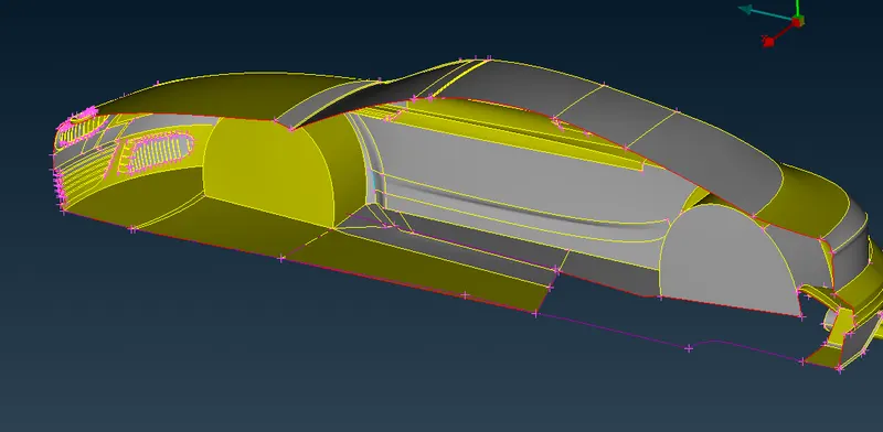 |
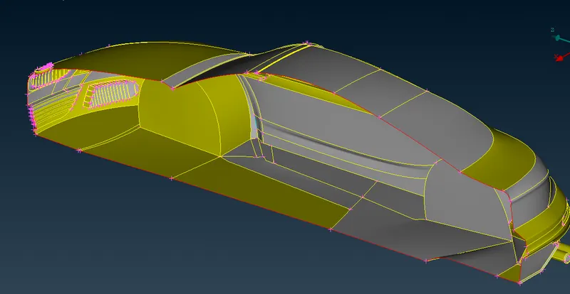
Floor cleanup completed without any intersections and errors.
----------------------------------------------------------------------------------------------------------------
|
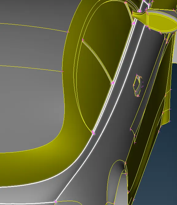
Intersection error between these surfaces was cleared by removing thin surface and making a new surface by inserting hot points between connecting edge of larger surface. Before/After comparison is shown-->. |
 |
|
----------------------------------------------------------------------------------------------------------------
TYRES AND RIMS
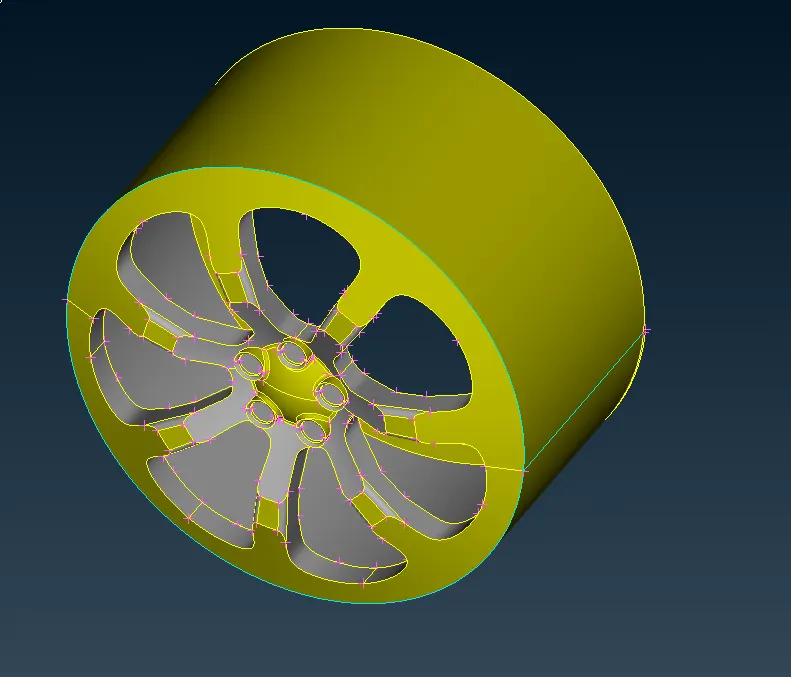
Tyres are having triple cons in rims these are two overlapping semicircular surfaces which were deleted.
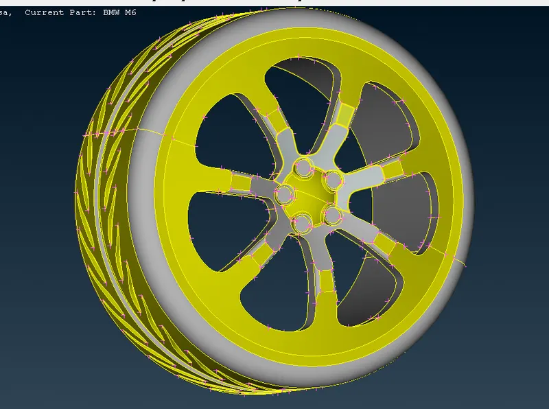
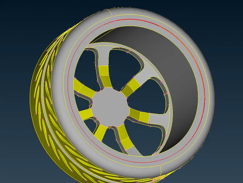
These red cons were removed using faces--> New---> Coons option. Similarly other tyre was cleared from errors.
----------------------------------------------------------------------------------------------------------------
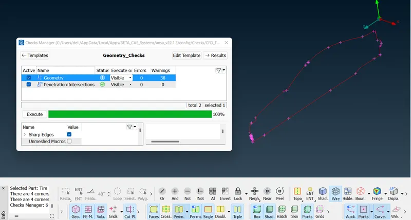
Upto this stage geometry clean-up is completed, all errors and intersections are vanished. Next steps would be mesh-generation for given target lengths and quality parameters, Volume formation of wind-tunnel, Volume meshing and Finally copying of symmetrical geometry.
----------------------------------------------------------------------------------------------------------------
PID ASSIGNMENT
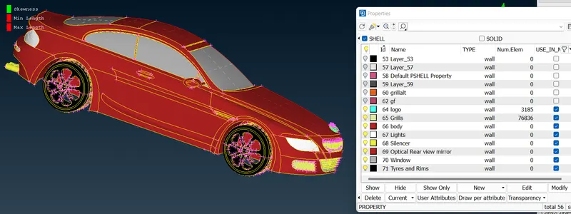
PID was assigned successfully for differenet parts for assignment of different target lengths.
----------------------------------------------------------------------------------------------------------------
MESHING
Specified Element Size
|
COMPONENTS |
Target Size in mm |
Minimum Size in mm |
Maximum Size in mm |
|
Body |
3 |
1 |
5 |
|
Lights |
4 |
2 |
5 |
|
Grills |
1 |
0.4 |
2 |
|
Rims and Tyres |
2 |
1 |
3 |
|
Optical Rear-view mirror |
2 |
1 |
3 |
|
Window |
2 |
1 |
3 |
|
Silencer |
3 |
1 |
5 |
|
Logo |
1 |
0.4 |
2 |
Skewness:0.5
Minimum Length:0.5
Maximum length:7
Freeze/Unfreeze commands were utillized throughly.
Perimeters Spacing---> Auto CFD algorithm was used for meshing.
For smooth transition; free-mesh algorithm was utilized.
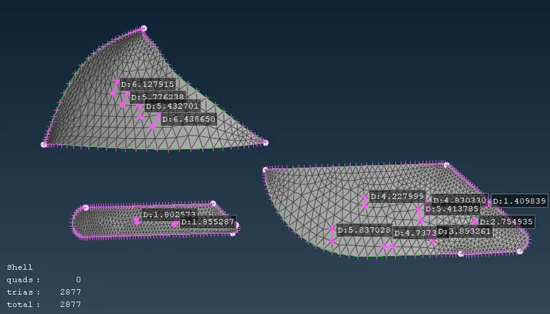
Lights=4mm
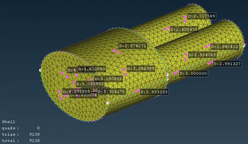
Silencer =3mm
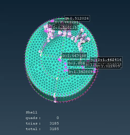
Logo =3mm
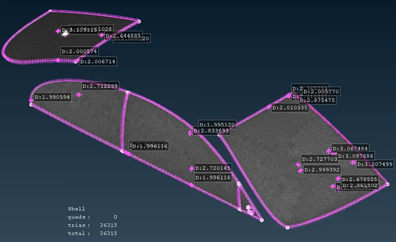
Window =2mm
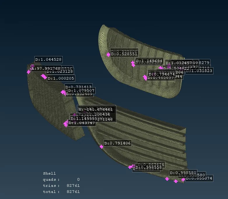
grills=1mm
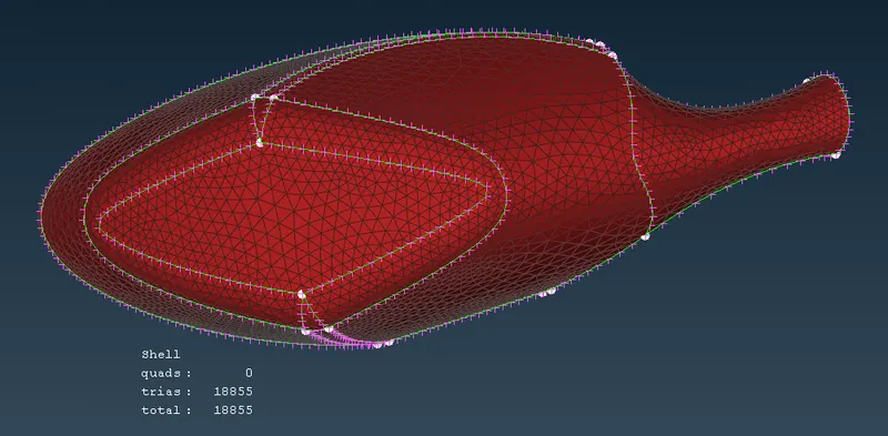
Optical Rear View Mirror: 2mm
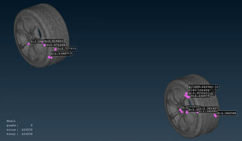
Rims and Tyres=2mm
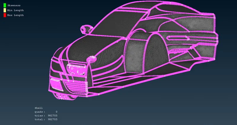
Body=3mm
----------------------------------------------------------------------------------------------------------------
Symmetrical part Mirrored.
Transform tool was used to copy mirror part. Mirror 3 Points Plane from dropdown menu was utilised to select three points from the symmetrical edge.
There were options X1 X2 & X3, these box is required to be filled with coordinates.
Select three points then boxes will be automatically take coordinates of those points.
remaiming errors were rectified after symmetry operation.
There was no penetration and intersections in full body geometry, warnings were visible due to convex and concave cons.
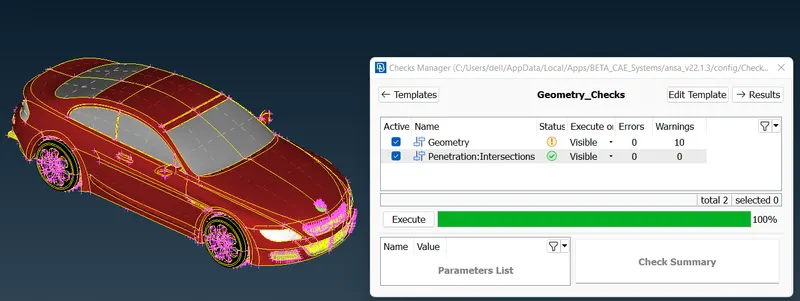
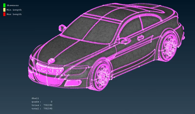
All off-elements were eliminated.
----------------------------------------------------------------------------------------------------------------
WIND TUNNEL CREATION
Create a wind tunnel around car.
Measurement for wind tunnels as parametrized by experimentalists and researchers.
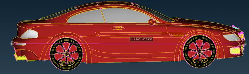
- Consider length of car as X where X~1310.
- Wind tunnel at `150mm distance from bottom of car
- Length of wind tunnel from front of car should be 4X, total length of tunnel in front is half length of car added to 4X length
- Length of wind tunnel from back of car should be 6X, total length of tunnel from rear side is half length of car added to 6X length
- Height of wind tunnel should be 3X
- Enable cons.
- select relative points option from point tool and select a point in middle of car from bottom side
- A dialogue box will appear, see your coordinate axes, To create a point at bottom of car say 200.
- With reference to that point create a point in front of car at distance 5820 in Z direction.
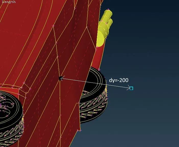
A point is created using TOPO--> Points--> Relative--> Select the hot point/Nodes and then Middle click. Assign demension dy as -200.
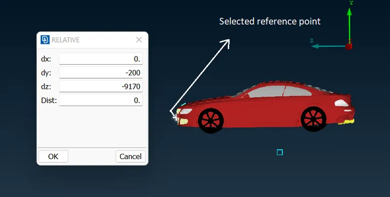
Distance of back face reference point from frontmost point would be:dz=`6x+x`=`7x=7*1310=9170`; dy=200.
Distance of back face reference point from frontmost point would be:dz=`4x`=`4x=4*1310=5240`; dy=200.
For side faces length equal to body longitidnal dimension can be kept.
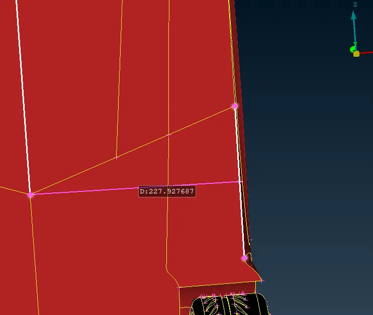
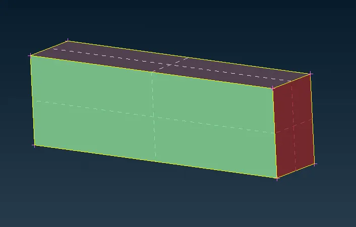
Translate these points to left and right sides of geometry by 1310+230=+/-1540 +/- for both sides of dx. These coied points were joined by curves and new surface was created using COONS option.
|
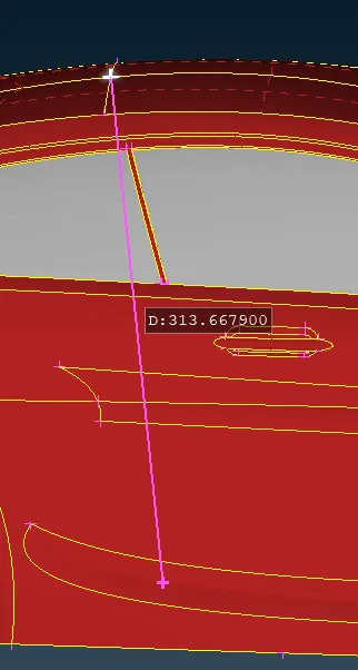
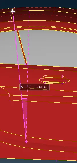
Height of car can be calculated as `313.67cos(7.13^@)=313.331`.
Bottom face is copied as top face by transform--> Copy by `315+200+3x=4445`
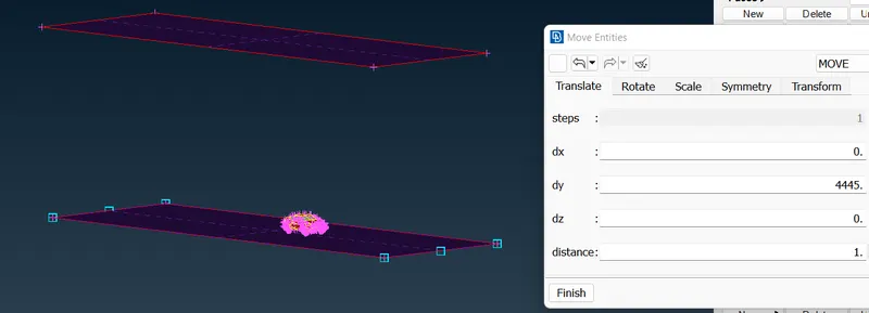
Surfaces are created using coons command.
- Top surface of wind tunnel would be meshed with 100mm mesh length
- Bottom surface would be meshed with 20mm mesh length.
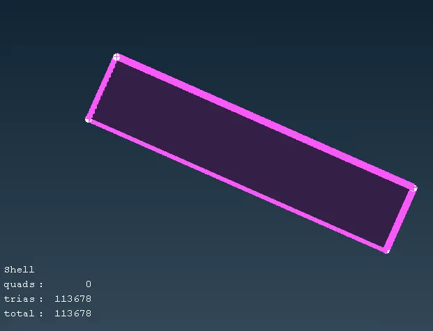
Bottom face meshing of target length 20mm.
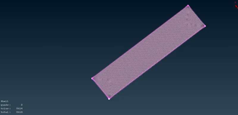
Top face meshing of target length 100.
Now, at other surfaces mesh growth would take place from 20 to 100mm
For transition mesh on side walls, inlet and outlet we need to utilize manual spacing option. As aerodynamic studies are done on automotive body, there is no need of finer mesh at top walls and size walls. In most simulations side walls are kept as 2D walls thus having symmetry boundary conditions. To capture Near wall effect we need more finer mesh for flow over automotive body. Mesh size increases in y+ direction (Dimensionless wall parameter).
USE OF SPACING TOOL
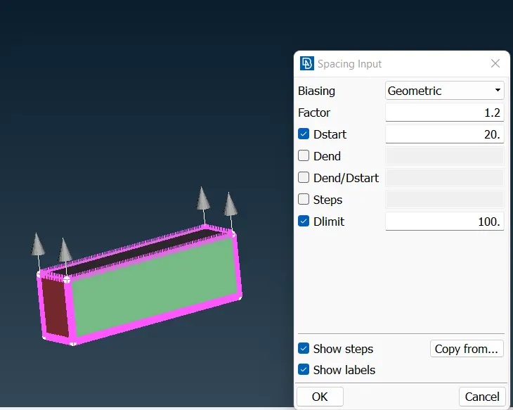
Arrow direction appears in the direction of mesh growth.
After creating top and bottom meshes it time for meshing sides of tunnel. In order to mesh sides of tunnel we will use spacing
Spacing tool varies mesh length from bottom to top, given min length as 30mm and max limit as 100mm and select factor of 1.1.
Steps involved
- Spacing tool give dmin and dlimit and spacing factor 1.2. Spacing factor varies length from bottom top by factor of 1.2.
- click on ok and select sides and do middle click.
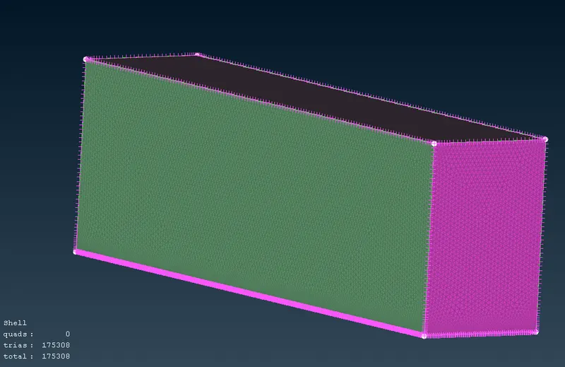
ANSA File link: BMW M6 meshed with wind tunnel
CONCLUSION-
- Working on BMW model made ANSA preprocessing faster due to practice.
- Different tools other than common cut, TOPO were used such as project cut, face extend etc.
- Curve tool was utilised for copying profile of floor curves by cons2curves.
- Free mesh algorithms, Freeze/Unfreeze algorithms were utilised for treatment of common perimeter problems.
- Mesh was constructed within quality paramaters.
- Off elements were cleared using Reshape, Reconstruct and Move commands.
- Creation of wind tunnel with help of points and curves.
- Advance topo-cleanup is done.