Week 4 Challenge
1. TOOLING AXIS:
In the process of manufacturing of any component using moulding approach, it is necessary to find a proper direction in which the product can be practically placed between the core and cavity of the mold. By utilising this direction, the material can be easily withdrawn from the mold after solidification without being stuck. the imaginary axis drawn in the direction of this application is known as tooling axis.
2. Creating tooling axis for the given lens Class A:-
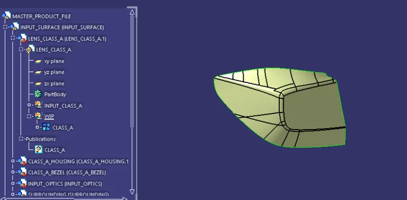
point definition:
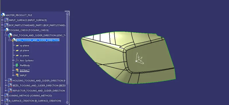
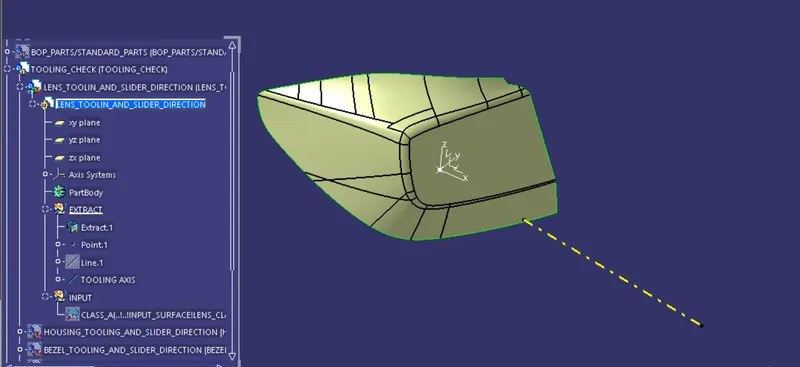
Tooling axis drawn in the imaginary direction as per the design:
Checking the feasibility of tooling axis using 10 degree draft analysis:
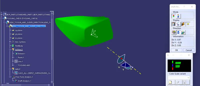
The given tooling axis can be utilised for making of this lens part.
3.PARTING LINE:
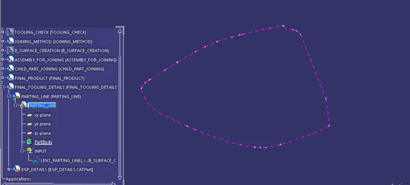
When designing core and cavity for the molding process, it is decided that which areas of the part will be in the core part and in the cavity part. there will be a specific line that splits the surface area of the object into 2 segments. This line is commonly known as parting line. Usually parting line is incorporated along the edges of the model.
4. Making of B surface for the lens Class A:
generative shape design workbench is used For this process. it has the tools necessary for making complexx surface geometries.
Part thickness= 4mm
process starts by offseting the class A to -4mm. it generates the B surface.
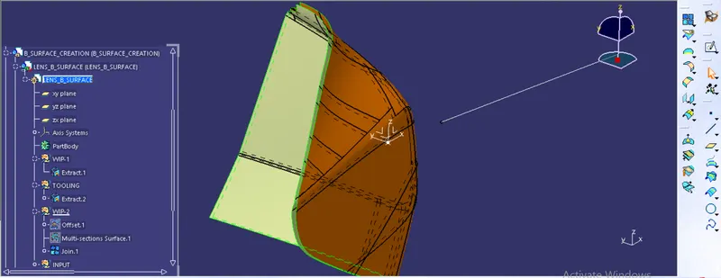
To join the class A and B surfaces we can use multiple methods.
First i'm using the method of sweeping the edges along the tooling direction.
For this, extrcating the edge lines with tangent continuity, and using sweep command making sufaces as shown.
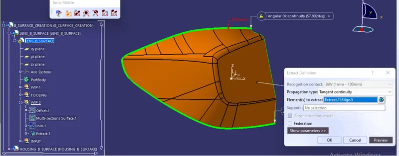
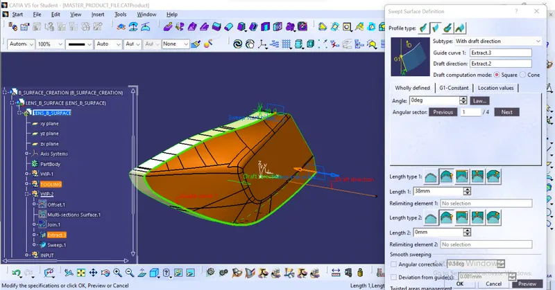
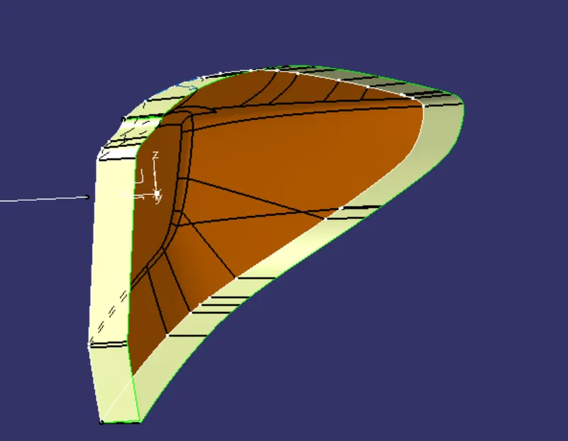
to join with this surface, it need to extrapolate the Bsurface until both intersects completely. Any open boundaries will result in failures.
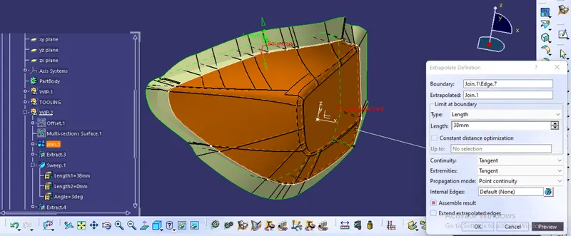
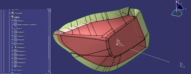
Trimming these surfaces together makes the required thickened part of the lens.
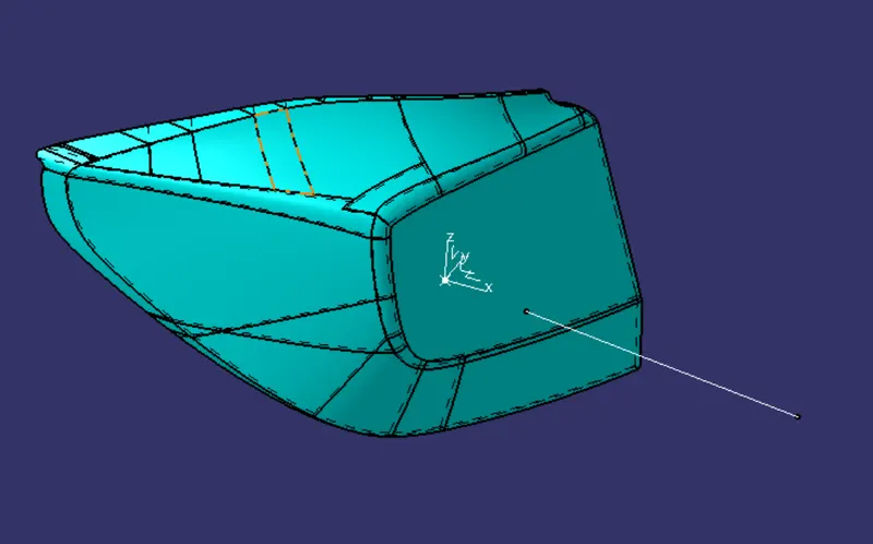
But, we can see that this part involves so many sharp edges and corners. these will result in inproper molding.
So i'll change the method of this surface joining.
By this new method we can Blend the edges of Class A and B surfaces together to close the boundaries.
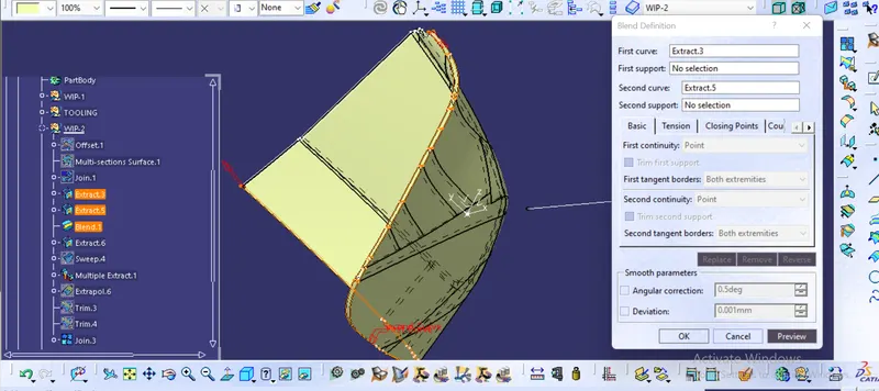
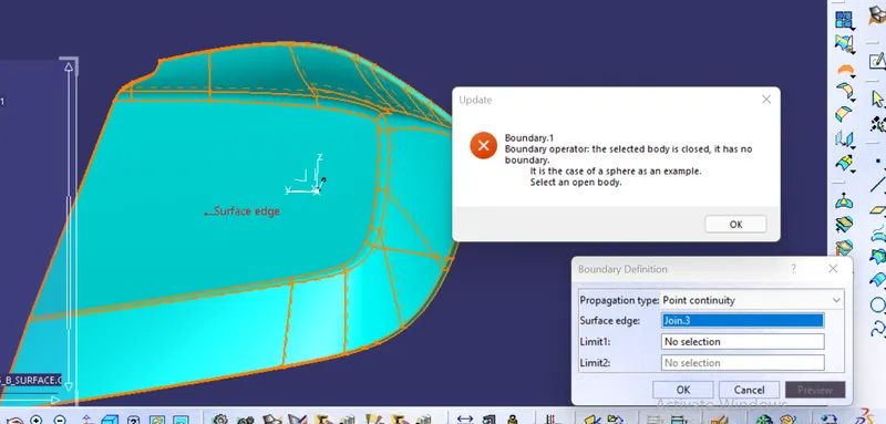
After doing necessry operations, close all the boundaries, and make the surface product into solid part using closesurface command in the part workbench.
Result of Draft analysis:
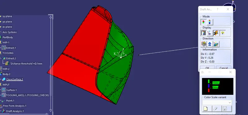
We can see the clear split of surface of red and green areas, The line that differs these can be considered as partimg line for this Lens.
5. Creating Parting line:
Applying fillets to all unwanted sharp edges:
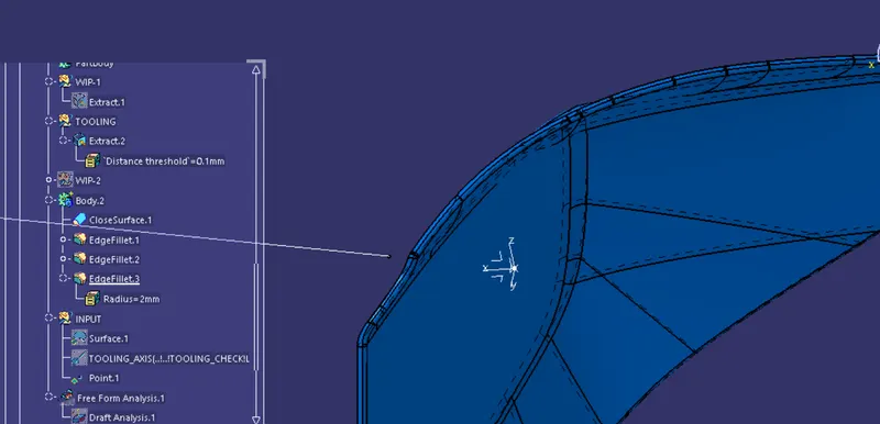
Extracting the parting line with tangent continuity:-
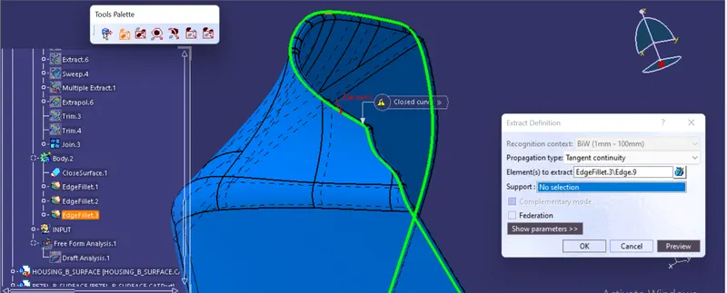
Defined Parting line:
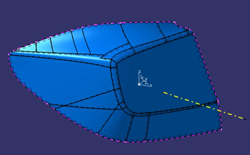
Finalised product design:
Conclusion:
Learned about product structure and designing principles in a part design process using catia. Practised the creation of all necessary features required in making important details like tooling axis and parting line,...