Week 4 Challenge
In this challenge, an automotive lighting lens is designed and developed with the specified requirements, and by the following design, rules followed in an OEM.
Given input (Class A Lens)
Class A surface
- Class A surface is a visible surface that has some aesthetic properties, designed with high efficiency and quality
- These surfaces are designed by the designer using the software Alias and give the surface to the product designer to model the complete product.
TOOLING AXIS
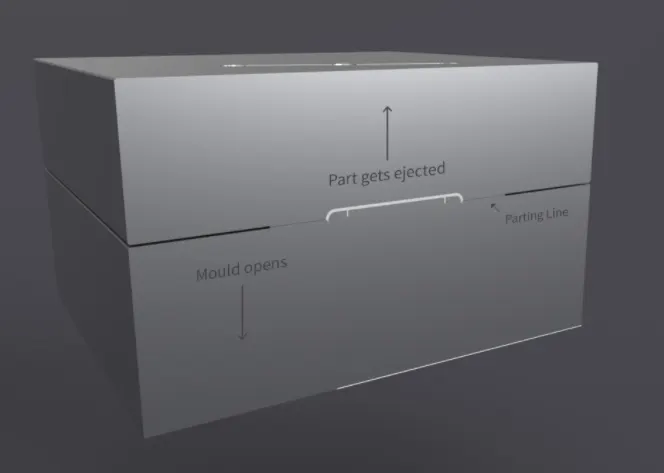
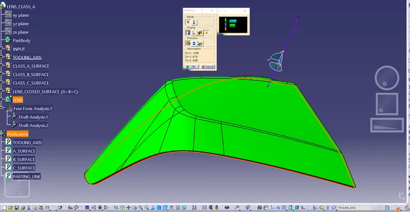
The tooling axis is the direction in which the mold or core and cavity get opened and the component is ejected. Clearance of the component is checked using this tooling axis. This means all the faces of the component when ejected along the tooling axis, must come out of the mold easily, without failing.
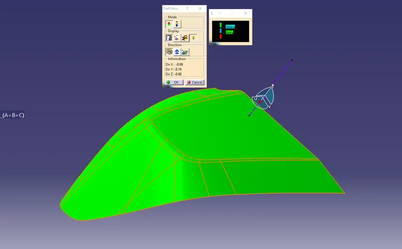
Here the tooling direction is created by taking a 10 deg draft.
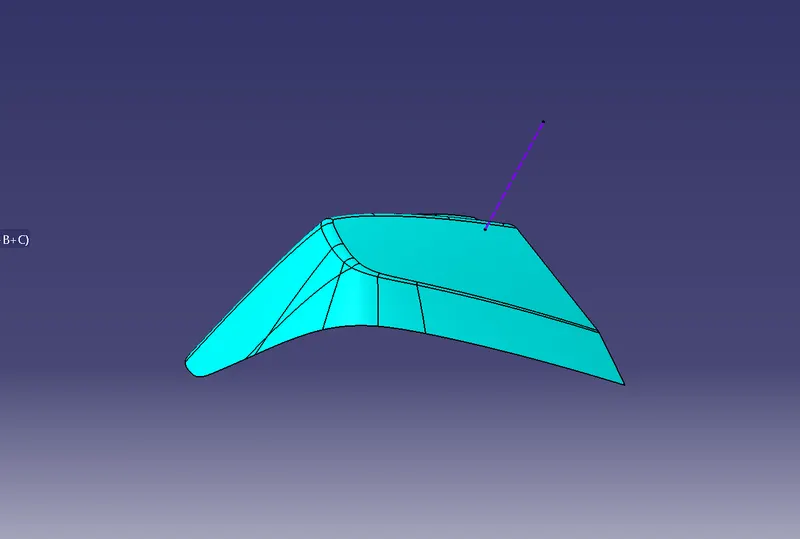
Draft analysis on class A surface
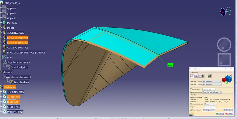
Class B surface
The thickness of the part is 4mm. So the B surface is created by taking an offset of 4mm from the A surface.
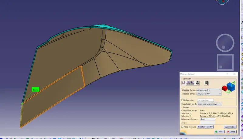
Class C surface
- C surface is designed to join the class A and B surfaces.
- This surface is created along the tooling axis with a specified draft on it.
- It is the thickness region in between A and B surface
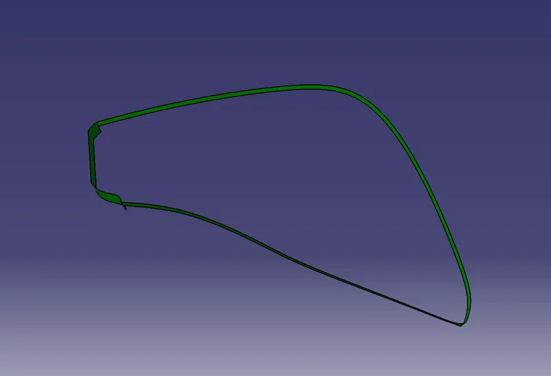
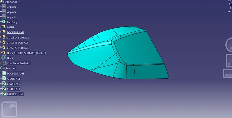
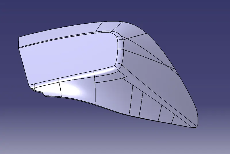
Closed body
Using above all the three surfaces (A, B, and C) and maintaining a thickness of 4mm the closed body is generated
Draft analysis on the closed body
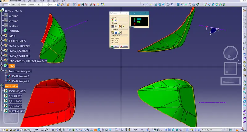
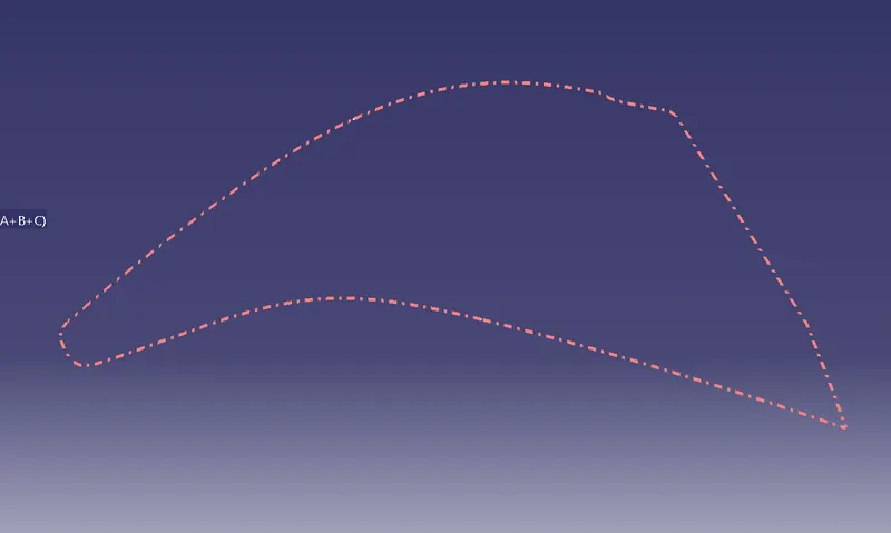
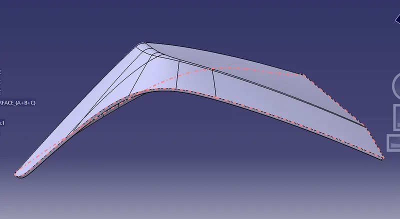
Parting line
- The parting line is where the two halves of the mold meet around the parameter of the part. In simple words, it is the junction b/w core and cavity halves. Mostly the parting line forms on the B surface but in some cases, it might also be on the A surface.
- The parting line also includes side action pins, tool inserts, and shutoffs. Every part has a parting line