Week 4 Challenge
Question No 1: Answer
Dead Load Calculations through Excel Sheet:
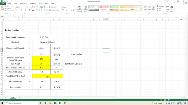
Aim :Calculate dead load in design report based on IS code and apply dead load on the model
- Finishes of 50mm
- Slab as per design
- Brickwall 150mm thickness
- Roofing load based on purlin size
- Ceiling loading 0f 0.3KN per sq m
Procedure :
- Finishes of 50mm thick.
Step1: Click On Load tab.
Step2: Click On Load Through Ribbon.
Step 3:Select laod Cases and add wind seismic and impose load.
Step 4: Click On load combinations and then select Next and finish tab as the combination is properly done.]
Step 5:Click on bottom Loading Window at bottom strip of window select dead load.
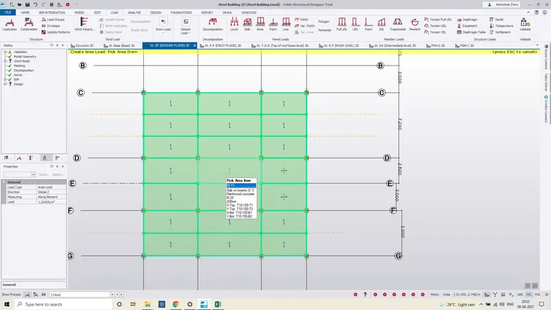
Step 6: Then thorugh property window select area load and set the value 1.2KN as calculated on excel sheet.
Step 7: Select Proper area load and select the slab panels where the finishes to be applied.
Conclusion : Hence Finishes Load of 50mm thick 1.2KN is calculated and applied on the Model.
Finishes Load applied on the Slab Panels.
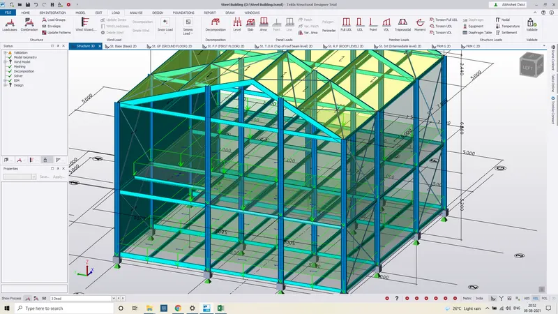
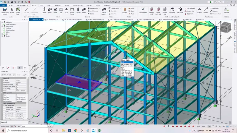
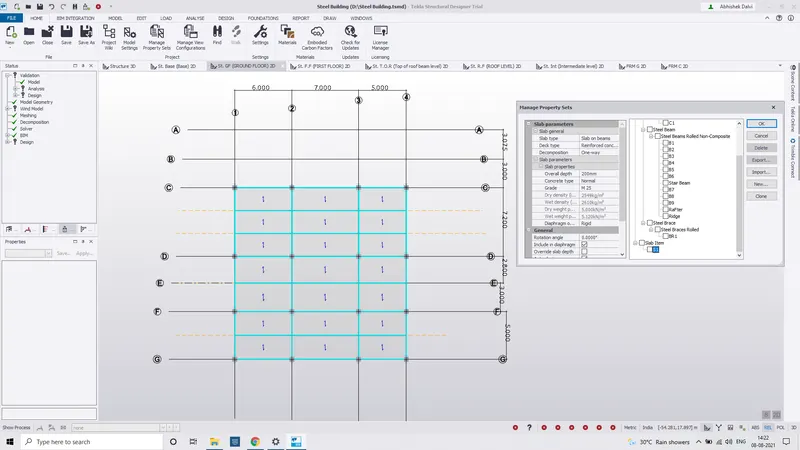
- Slabs as per Designs.
Procedure:
Step 1:Select the Ground floor Level through construction levels.
Step 2:Click On Home and manage property sets.
Step 3:Select New and then select Slab
Step 4: Select slab type Slab on beams Select One way if the longer to shorter span is greater then 2.
Step 5:Select Two way if the longer to shorter span is Lesser than 2.
Step 6:Set overall depth 200mm,Grade M25.
Step 7: Reinforcement 10mm Bars @ 150mm spacing.
Step 8: rename as S1
Step 9: Than go to Model tab select slabs on beams set rotation angle to 90degree
Step 10: Select the panel where the slab should be model jst select one way and start modeling.
Step 11: Similarly create 2nd property and rename it as S2 and slab type two for Two slab model.
Conclusion: hence Slabs one way and two way are modelled in the plan.
- Brickwall 150mm thickness
Procedure:
Step1: Click On Load tab.
Step2: Click On Load Through Ribbon.
Step 3:Select laod Cases and add wind seismic and impose load.Select dead load
Step 4: Click On load combinations and then select Next and finish tab as the combination is properly done.]
Step 5:Click on bottom Loading Window at bottom strip of window select dead load.
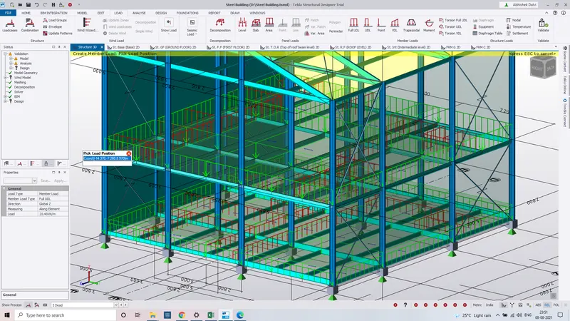
Step 6: Then thorugh property window select Member load and line load Set the value 15.6KN For G.F to F.F Similarly F.F to Roof 20.4KN is calculated on excel sheet.
Step 7: Select Proper Member load and click on fully udl option and select the walls on whch load should be applied which are shown on plans and similarly clicking on line load draw the internal walls on the plan in the way where the Bricks wall load to be applied.
Conclusion : Hence Brick wall loading for Ground floor to First floor is 15.6KN and For Fisrt floor to roof is 20.4Kn is calculated On Excel Sheet in refernce to IS 875 Part 1 And value is applied on the model.
- Roofing load based on purlin size
Step1: Click On Load tab.
Step2: Click On Load Through Ribbon.
Step 3:Select laod Cases and add wind seismic and impose load.
Step 4: Click On load combinations and then select Next and finish tab as the combination is properly done.]
Step 5:Click on bottom Loading Window at bottom strip of window select dead load.
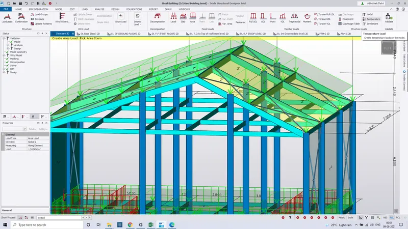
Step 6: Then thorugh property window select area load and set the value 1.5KN/M^2 as calculated on excel sheet.
Step 7: Select Proper area load and select the Roof panels where the Roof Load to be applied.
Conclusion : Hence Roof Load 1.5KN/M^2 is calculated and applied on the Model.
- Ceiling loading 0f 0.3KN per sq m
- Procudure:
Step1: Click On Load tab.
Step2: Click On Load Through Ribbon.
Step 3:Select laod Cases and add wind seismic and impose load.
Step 4: Click On load combinations and then select Next and finish tab as the combination is properly done.]
Step 5:Click on bottom Loading Window at bottom strip of window select dead load.
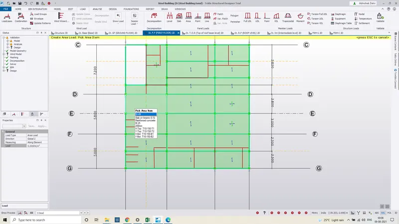
Step 6: Then thorugh property window select area load and set the value 0.3KN/M^2 as calculated on excel sheet.
Step 7: Select Proper Area load and Select the Fisrt Floor slab Panels where the Ceiling Load to be applied.
Conclusion : Hence Ceiling Load 0.3KN/M^2 is calculated and Applied on the Model.
 .
.
Question No 2: Answer:-
Aim:- Calculate live load in design report based on IS code and apply live load on the model.
- Assume the loading based on IS 875 Part 2
Procedure:
Step : Create Excel Sheet and Through IS 875 Part 2 Generate all Live Loads On Models and apply on Particular sections Simultaneosly.
Conclusion : Live Load value in the Model are Assumed as per IS 875 Part 2.
Live Load Calculations:
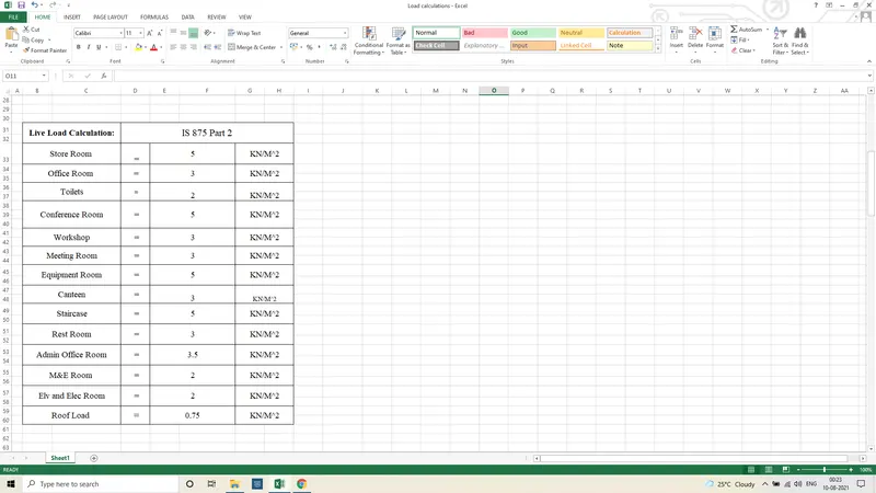
- Roof loading Of Live Load.
Procudure:
Step1: Click On Load tab.
Step2: Click On Load Through Ribbon.
Step 3:Select laod Cases and add impose load.
Step 4: Click On load combinations and then select Next and finish tab as the combination is properly done.
Step 5:Click on bottom Loading Window at bottom strip of window select Imposed load.
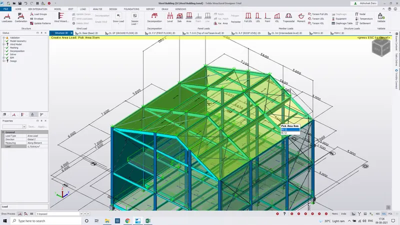
Step 6: Then thorugh property window select Area load and Set the value 0.75KN Which is being selected through IS 875 Part 2 as calculated on Excel sheet.
Step 7: Select Proper Area load and Select the Roof Panels where the Roof Live Load is to be applied.
Conclusion : Hence Live Load For 0.75KN is calculated and applied on the Model.
Live Load Applied on the Roof Panels.
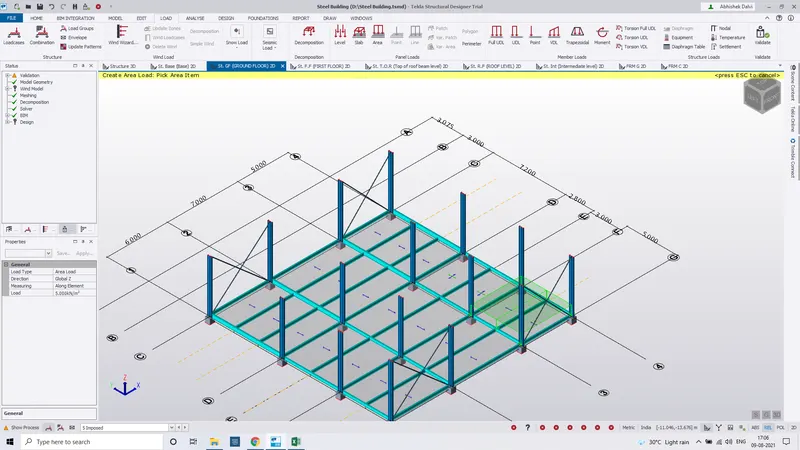
- Consider equipment loading as 5KN per sq m
Procedure:
Step1: Click On Load tab.
Step2: Click On Load Through Ribbon.
Step 3:Select laod Cases and add impose load.
Step 4: Click On load combinations and then select Next and finish tab as the combination is properly done.
Step 5:Click on bottom Loading Window at bottom strip of window select Imposed load.
Step 6: Then thorugh property window select Area load and Set the value 5KN Which is being selected through IS 875 Part 2 as calculated on Excel sheet.
Step 7: Select Proper Area load and Select the Equipment Area Panels where the Equipment Live Load is to be applied.
Conclusion : Hence Equipment Live Load For 5KN is calculated and applied on the Model.
Question No 3 :Answer
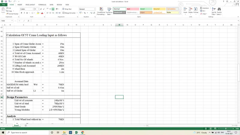
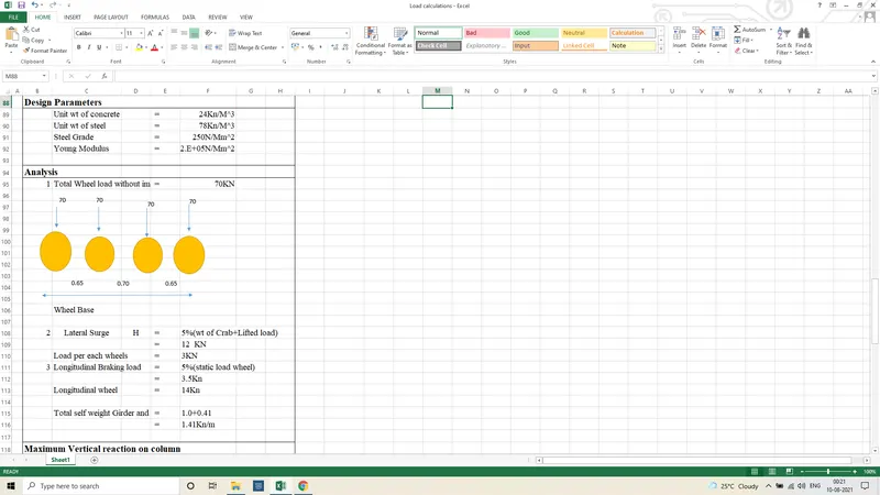
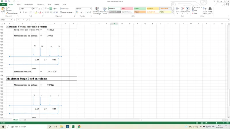
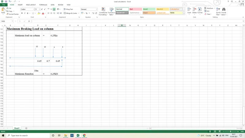
Aim: Generate a calculation for 5T crane loading based on following inputs
- Centre to Centre of wheel = 10m
- Weight of crab = 40 KN
- Number of wheels = 4
- Wheel base = 2m
Procedure:
Calculations are Done and Shown As per Excel Sheet Explained below.
 .
.