Week 1 Challenge
Question No 1:--
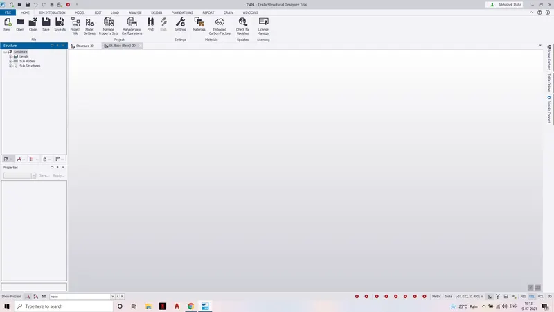
Anwser 1 Aim - Project Work Space How to access and usage?
Procedure - Steps to follow
Step 1- Click On Tekla Structural Designer Icon on Desktop.
Step 2- On left hand side Top Click on File than New Icon.
Step 3- After Opening on structure 2d window on main screen Left hand side hand
structure,Levels,Sub model,Sub structure icons are shown.
Step 4- Structure levels,sub models and sub structure icons are represented as Project workspace
Usage- 1. Project workspace provides infornmation regarding the model,loading and validation.
2. It shows various levels arranged in the model.
3. Group icon at bottom of project work space window shows Various Design parameters and Design information For model parts.
4.Laoding shows all input loadings.
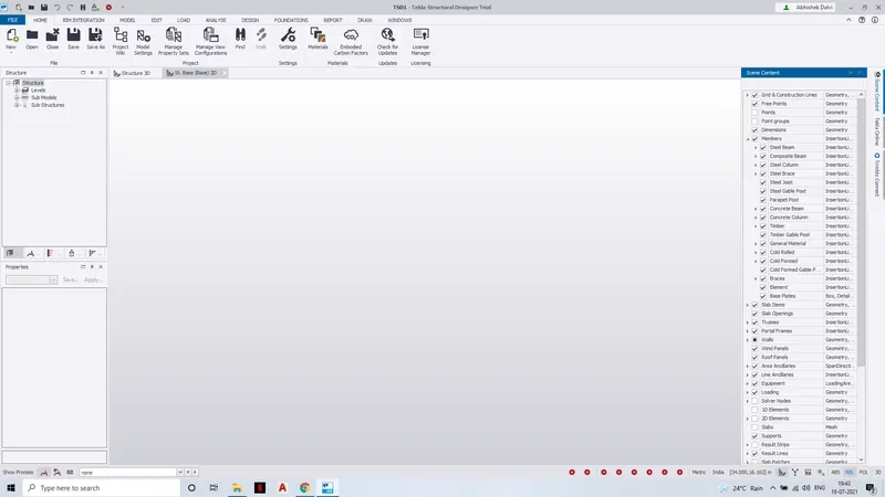
Answer 2 Aim - Scene Content- Demonstrate the use of scene content.
Procedure-
Steps:-
Steps 1: Click In file option
Step 2 : Click On New Tab
Step 3 : Scene content icon is shown on right hand side of main Screen window.
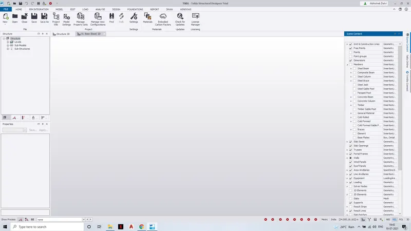
Answer 3. Aim - Create two scene views.
Procedure: Steps:-
Scene View 1- All Ticks options view
Steps 1 - Click on Scene content on right side of screen.
Step 2 - Click on member option it will be showing all ticks on member option.
Scene View 1- Non Ticks options view
Steps 1 - Click on Scene content on right side of screen.
Step 2 - Click on member option and select particular member to show in the model it will be showing all ticks on member option.
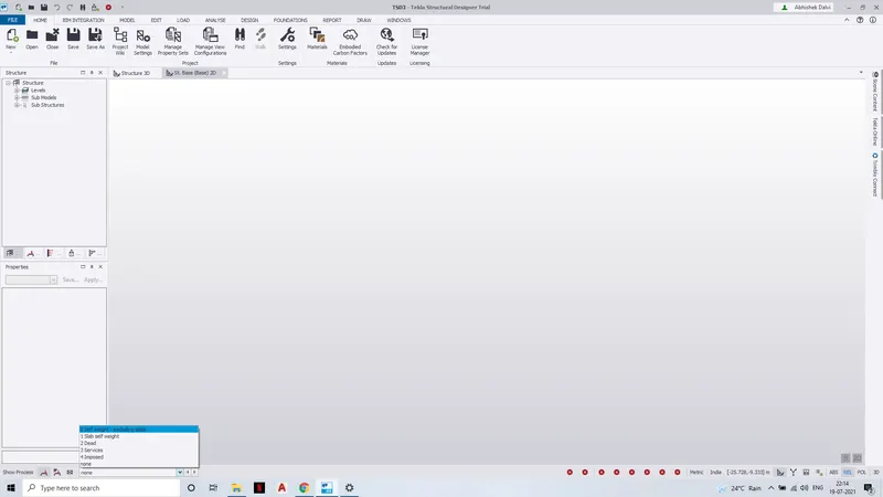
Answer 4 Aim- Loading drop list
Procedure :
Step 1 : Click On file option
Step 2 : Click on new file tab
Step 3 : Click on loading list on bottom of the main Screen.
Answer 5.Aim- Properties Window and usage :-
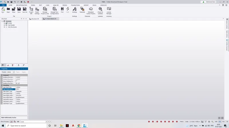
Procedure - Steps as follows:
Step 1: Click on Tekla Structural Designer
Step 2: Click on File option then click on new tab
Step 3: Click on structure tab on project work space option.
Step 4: Below the Project work space window Property window will be shown.
Usage :-
Property window is use to view or edit the member and properties, To check the number of sizes in the model are correct or not.
Question no 2:-
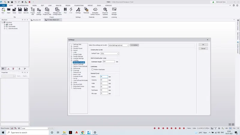
Answer Aim - Create a new file in TSD and set up the settings for a steel building to have member grade FE410 and concrete grade of M30 as per IS codes. The covers for the members to be as per the following input: -
Procedure: Steps to follow
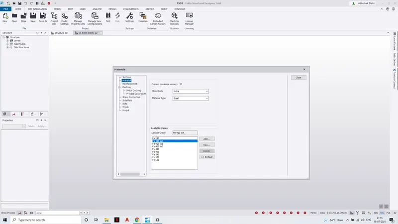
Step 1 : Click on the File Tab
Step 2 : Click on new file tab option
Step 3 : Click on material Tab
Step 4 : Click on Material Type select steel
Step 5 : Select Fe410
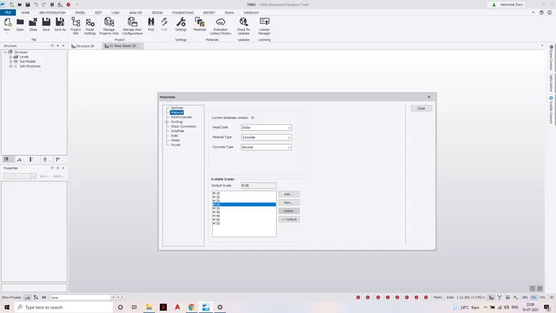
Step 6 : Click on Conrete through Material type
Step 7 : Click on concrete grade M30.
Concrete Grade M30
Aim : Selection of covers for the members:
Procedure: Steps
Step 1 : Click On file option
Step 2 : Click on Settings Option
Step 3 : Click on Structural Defaults option
Step 4 : Nominal Covers.
Questions No 3 :
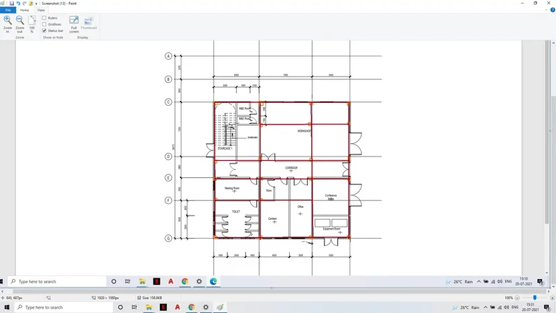
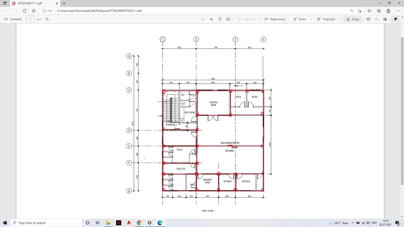
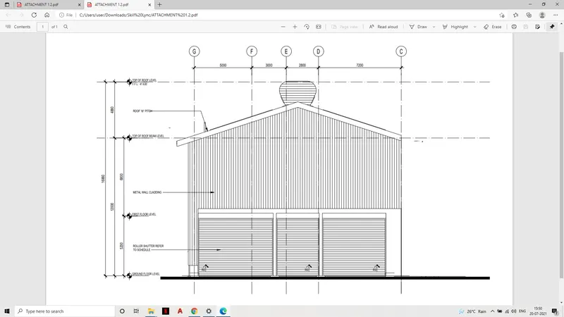
Answer : Aim : With reference to the input drawing as per Attachment 1, 1.1, and 1.2 and study the steel building plan and summarize your understanding of the plan. Based on your study assume and explain the location of columns and beam and develop a hand sketch for each plan
Plan Attachment 1
Plan 1.2:
Plan 1.2
Question no 4:
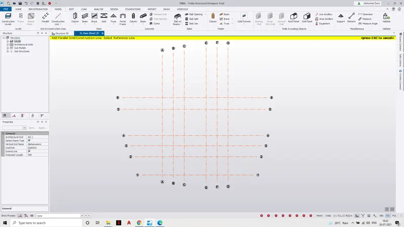
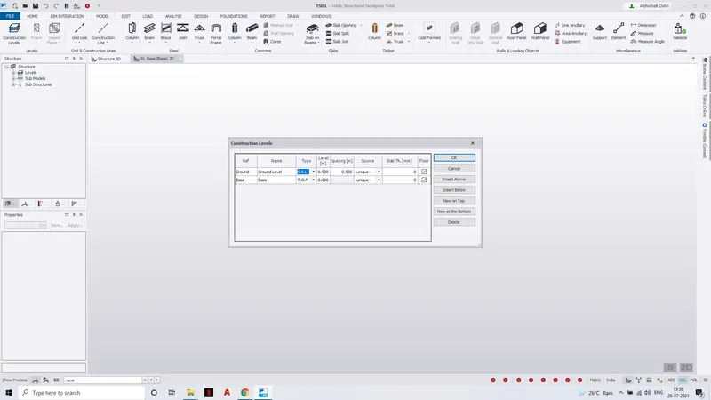
Answer Aim: To Model grid lines and construction levels as per Attachment 1. 1.1 and 1.2. All dimensions are in mm
- The base level to be 500mm below ground level.
Procedure: Steps
Step 1 : Click On File option then Click on New tab
Step 2 : Click On Model option through Ribbon.
Step 3 : Click on Construction level
Step 4 : Click on Insert above option
Step 5 :In spacing column option set 500mm.
Step 6 : Change 1 name to ground level.
Modeling Grid Line
Steps to follow
Step 1 : Click On File option then Click on New tab
Step 2 : Click On Model option through Ribbon.
Step 3 : Click on Grid line option
Step 4 : Click gird line option draw grid by clicking on 1 point and top and 2nd at bottom
Step 5 : Click on parallel grid line select reference grid line through the main screen option then set distance by clicking F2 and same by selecting two points final the grid line.