Week 4 Challenge
1.Nernst equation for fuel cell and parameters affect the reaction in a fuel cell.
The Nernst equation solves the potential of an electrochemical cell containing a reversible system with fast kinetics and it is valid only at equilibrium and at the surface of the electrode.
The maximum electrical work (Wel) obtainable in a fuel cell operating at constant temperature and pressure is given by the change in Gibbs free energy (∆G) of the electrochemical reaction:
W = ∆G = -n FE----------------------------------(1)
where n is the number of electrons participating in the reaction, F is Faraday's constant (96,487 coulombs/g-mole electron), and E is the ideal potential of the cell. The Gibbs free energy change is also given by the following state function:
∆G =∆H − T∆S----------------------------------(2)
where ∆H is the enthalpy change and ∆S is the entropy change. The total thermal energy available is ∆H. The available free energy is equal to the enthalpy change less the quantity T∆S which represents the unavailable energy resulting from the entropy change within the system. The amount of heat that is produced by a fuel cell operating reversibly is T∆S. Reactions in fuel cells that have negative entropy change generate heat (such as hydrogen oxidation), while those with positive entropy change (such as direct solid carbon oxidation) may extract heat from their surroundings if the irreversible generation of heat is smaller than the reversible absorption of heat.
For the general cell reaction,
αA + βB → cC+ δD-------------------------------(3)
the standard state Gibbs free energy change of reaction is given by:
∆G°=cG°c+ δG°D-αG°A-βG°B-------------------(4)
where G°i is the partial molar Gibbs free energy for species i at temperature T. This potential can be computed from the heat capacities (Cp) of the species involved as a function of T and from values of both ∆S° and ∆H° at a reference temperature, usually 298K. Empirically, the heat capacity of a species, as a function of T, can be expressed as
Cp=a + bT + cT2---------------------------------(5)
where a, b, and c are empirical constants. The specific enthalpy for any species present during the reaction is given by
H i = H°i +∫ Cpi dT ------------------------------(6)
Note (Integration is from 298 to T)
and, at constant pressure the specific entropy at temperature T is given by
S i = S°i +∫ Cpi/TdT------------------------------(7)
It then follows that
∆H =∑niHi |out-∑niHi|in--------------------------(8)
and
∆S =∑niSi |out-∑niSi|in---------------------------(9)
The coefficients a, b, and c, as well as H° and S°, are available from standard reference tables, and may be used to calculate ∆H and ∆S. From these values it is then possible to calculate ∆G and E at temperature T.
Instead of using the coefficients a, b, and c, it is modern practice to rely on tables, such as JANAF Thermochemical Tables to provide Cp, ∆H, ∆S, and ∆G over a range of temperatures for all species present in the reaction.
The Gibbs free energy change of reaction can be expressed by the equation:
∆G=∆G°+RT ln (fcfd/fafb)----------------------------(10)
where ∆ ° G is the Gibbs free energy change of reaction at the standard state pressure (1 atm) and at temperature T, and fi is the fugacity of species i. Substituting equn 1 in equn 10
E = E° + RT/nf ln (fcfd/fafb)-----------------------(11)
more generally,
E = E° + RT/nf ln π(reactant fugacity)/π (product fugacity)--------------------------------(12)
which is the general form of the Nernst equation. The reversible potential of a fuel cell at temperature T, E° , is calculated from ∆ ° G for the cell reaction at that temperature. Fuel cells generally operate at pressures low enough that the fugacity can be approximated by the partial pressure.
The Nernst potential, E, gives the ideal open circuit cell potential. This potential sets the upper limit or maximum performance achievable by a fuel cell. The overall reactions for various types of fuel cells are presented in Table 1
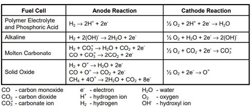
Table1: Electrochemical Reactions in Fuel Cells
The Nernst equation provides a relationship between the ideal standard potential (E°) for the cell reaction and the ideal equilibrium potential (E) at other partial pressures of reactants and products. For the overall cell reaction, the cell potential increases with an increase in the partial pressure (concentration) of reactants and a decrease in the partial pressure of products. For example, for the hydrogen reaction, the ideal cell potential at a given temperature can be increased by operating
at higher reactant pressures, and improvements in fuel cell performance have, in fact, been observed at higher pressures.
The reaction of H2 and O2 produces H2O. When a carbon-containing fuel is involved in the anode reaction, CO2 is also produced. For MCFCs, CO2 is required in the cathode reaction to maintain an invariant carbonate concentration in the electrolyte. Because CO2 is produced at the anode and consumed at the cathode in MCFCs, and because the concentrations in the anode and cathode feed streams are not necessarily equal, the CO2 partial pressures for both electrode reactions are present
in the second Nernst equation shown in Table 2
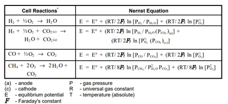
Table2: Fuel Cell Reactions and the Corresponding Nernst Equations
2. Consider the following operating points of a fuel cell during a short period of operation.
- 15 W/cm2
- 3 W/cm2
- 27 W/cm2
Where would these points go in the diagram below?
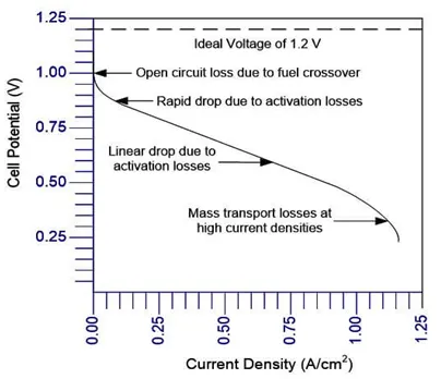
The performance of fuel cells is affected by operating variables (e.g., temperature, pressure, gas composition, reactant utilization, current density), cell design and other factors (impurities, cell life) that influence the ideal cell potential and the magnitude of the voltage losses. Current density is one of the fuel cell variable which effect the operating parameters of fuel cell.
As current is initially drawn, sluggish kinetics (activation losses) cause a decrease in cell voltage. At high current densities, there is an inability to diffuse enough reactants to the reaction sites (concentration losses) so the cell experiences a sharp
performance decrease through reactant starvation. There also may be an associated problem of diffusing the reaction products from the cell. Below graph1: Voltage/Power Relationship shows the relation ship between polarization curev & Power density against current density.
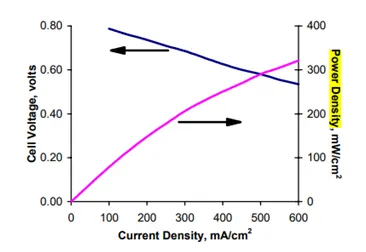
graph1: Voltage/Power Relationship
Ohmic losses predominate in normal fuel cell operation. These losses can be expressed as iR losses where i is the current and R is the summation of internal resistances within the cell, As is readily evident from the equation, the ohmic loss and hence voltage change is a direct function of current (current density multiplied by cell area). It would seem logical to design the cell to operate at the maximum power density that peaks at a higher current density (right of the figure). However, operation at the higher power densities will mean operation at lower cell voltages or lower cell efficiency. Setting operation near the peak power density can cause instability in control because the system will have a tendency to oscillate between higher and lower current densities around the peak. It is usual practice to operate the cell to the left side of the power density peak and at a point that yields a compromise between low operating cost (high cell efficiency that occurs at high voltage/low current density) and low capital cost (less cell area that occurs at low voltage/high current density). In reality, the precise choice of the operating point depends on complex system trade-offs, usually aided by system studies that allow the designer to take into account effects of operating voltage and current density on parasitic power consumption, sizing of balance of plant components, heat rejection requirements, and other system design considerations.
For the short period of fuel cell operations for 3W/cm2, 15W/cm2 & 27W/c2, pls find the belwo graph2.
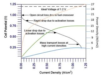
graph2: short period of fuel cell operations for 3W/cm2, 15W/cm2 & 27W/c2
3. Which among the three points is the best operating point and why?
The common practise is to operate at high voltage to get max power output, but operating at high voltage is under ideal condition. Due to the losses like activation loss, ohmic loss & mass transfer loss, the optimal operating point is as shown in the below graph3
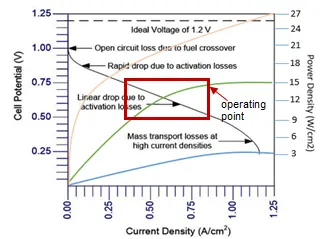
garph3: optimal operating point
• At low power densities, the cell potential drops due to activation polarization.
• At moderate current densities, the cell potential decreases linearly with current due to ohmic losses.
• At high current densities, the cell potential drop departs from the linear relationship with current density due to concentration polarization (mass transport losses)
From the above graph3, at 3W/cm2, cell potential is nearing to mass transport loss due to gas diffusion. At 27w/cm2, which is ideal condition with high operating voltage, but due to activation loss due to slow reaction & increased resistance, 27w/cms cannot be the optimal operating point. Hence 15W/cm2 is the optimal operating point where it falls in the region of ohmic loss which is linear.