Week 4 Challenge
Ans 1: Tooling direction refers to the orientation in which the moulds or tools are designed and manufactured for producing the plastic parts. The tooling direction significantly impacts the manufacturability, quality and overall performance of final plastic components.
Ans 2: Class A surface tooling axis could be created with the given input shown below:
Given input values for the draft analysis:
Created tooling axis on class A surface which clears the draft as shown below:
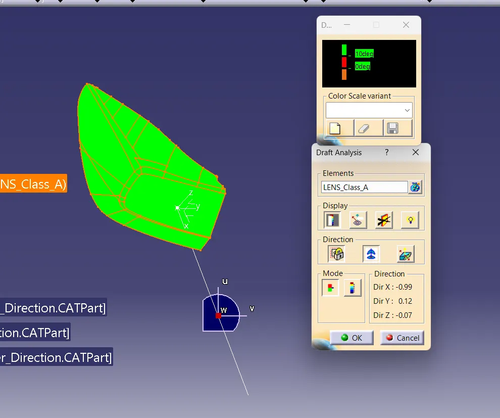
The green colour indicates that the whole surface is clearing the draft angle and we could move on with this surface for the next steps.
The procedure followed for the creation of the tooling axis as shown below:
- first, create a point on the front side of the surface, now add the axis system on that point.
- Create a line along the x-direction as shown in the above snap, and adjust the direction of the line by making the rotation of axes a few degrees, so that we get the clear draft of the class A surface in the above snap.
Ans 3: The parting line also known as the parting surface or mould split line, is the imaginary line that separates the two halves of a mold (core and cavity) used in the injection moulding. The primary function of the parting line is to create the boundary between the core and cavity halves of the mold.
Ans4:Report on creation of class B surface and draft analysis on that surface for checking its feasibility:
Aim: To create Class B the surface of the given lens could be created by following the below procedure as shown:
Given:
Given Class A surface:
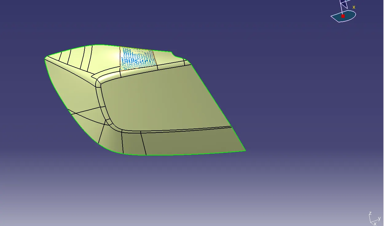
Report:
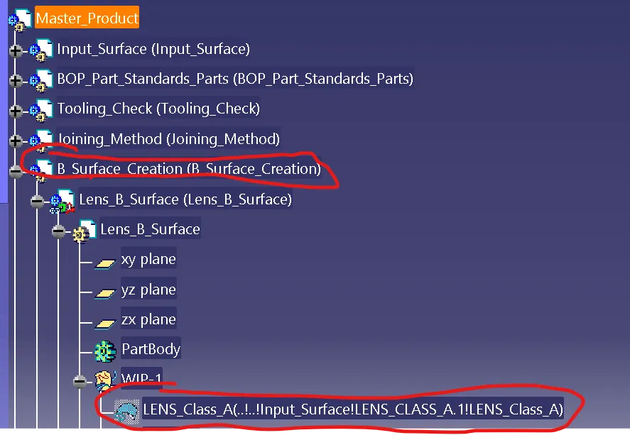
- First, copy the given input surface on the Lens class B product file, with paste special as result with link as shown below:
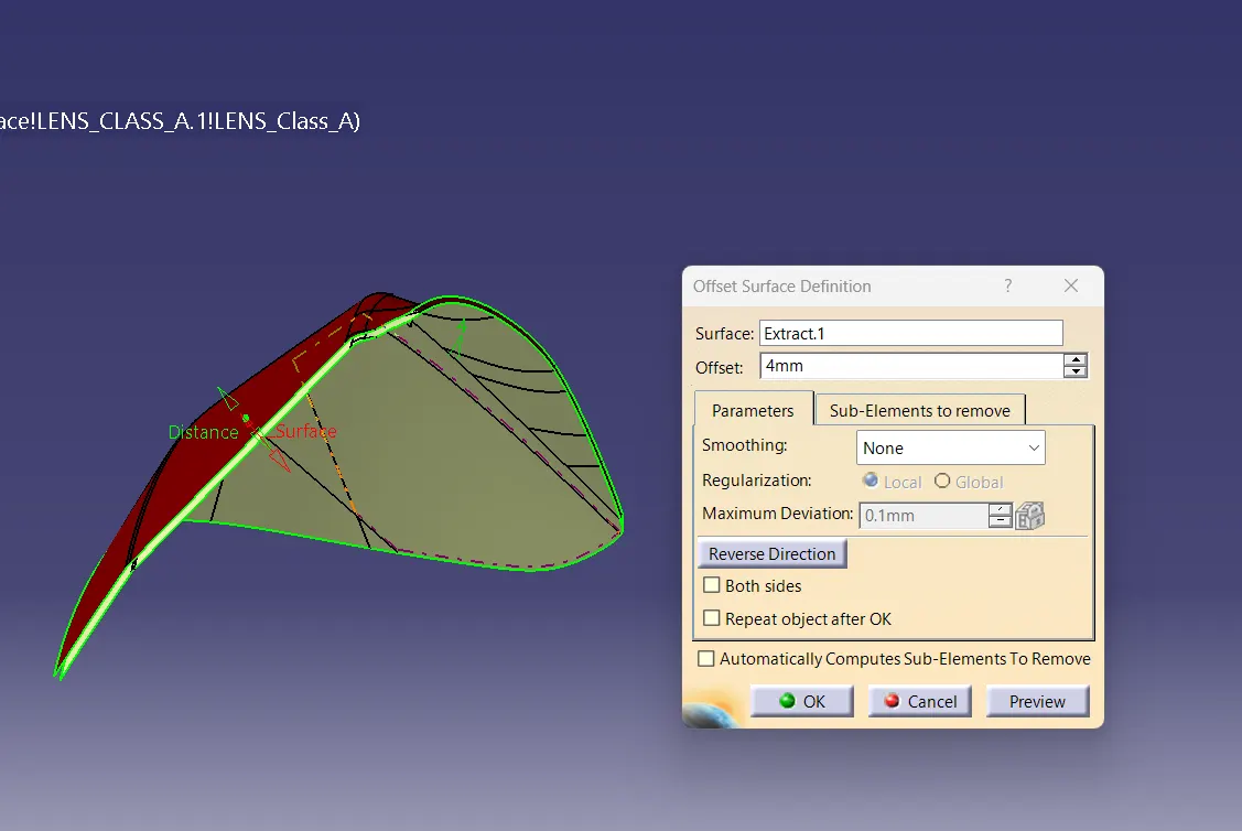
- Now we start working on this surface by making an extract of the given surface and offset it by 4mm.
- Improving that surface if any irregularities in that surface appear by using command multi-section surface.
- Now create class C surface on class A surface by using sweep command and join them.
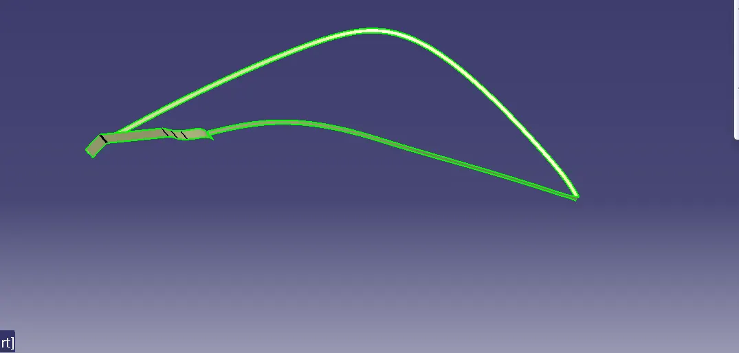
- And Trim the join of class A and Class C surfaces with extrapolated class B surface. To make a close surface as shown below:
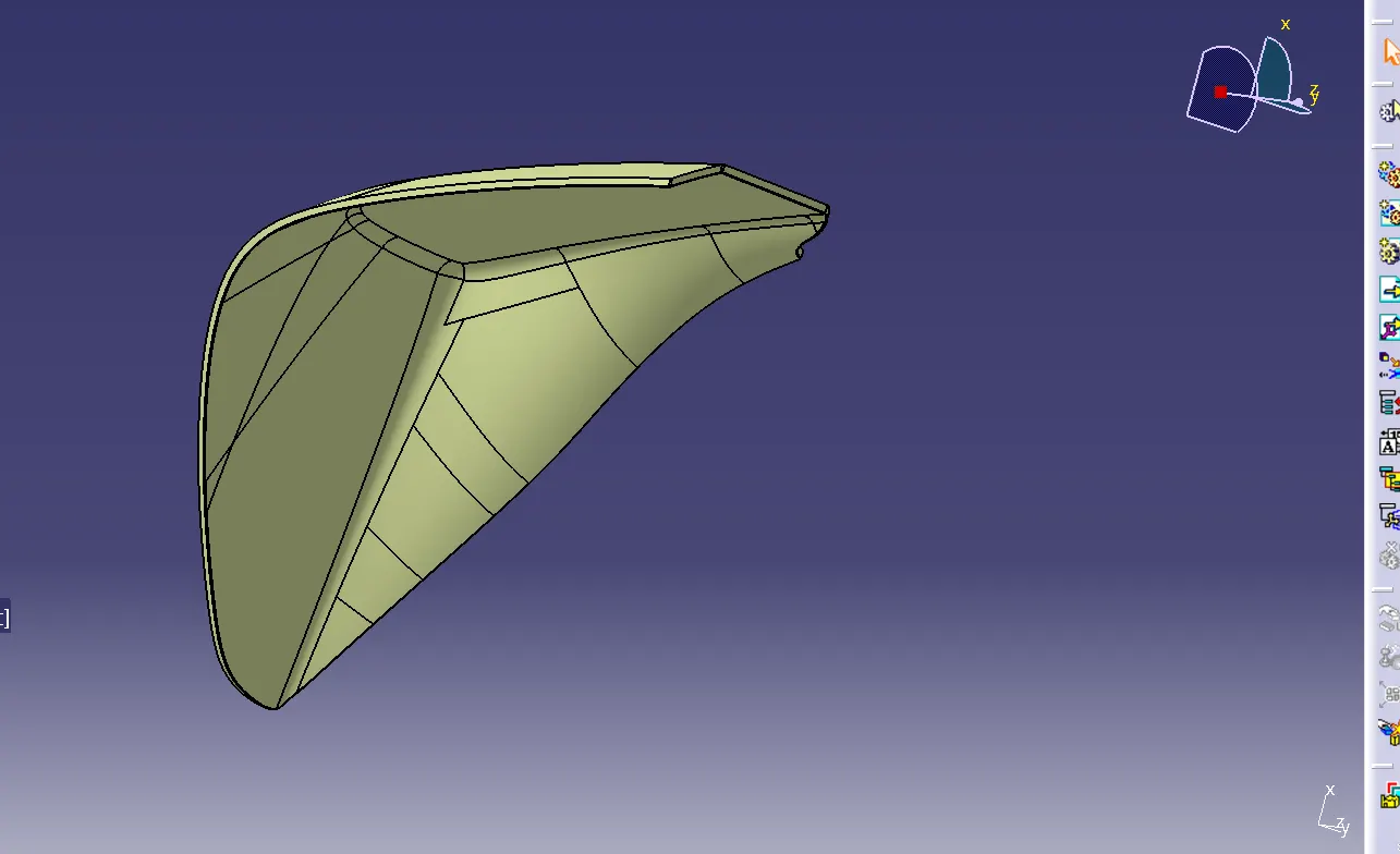
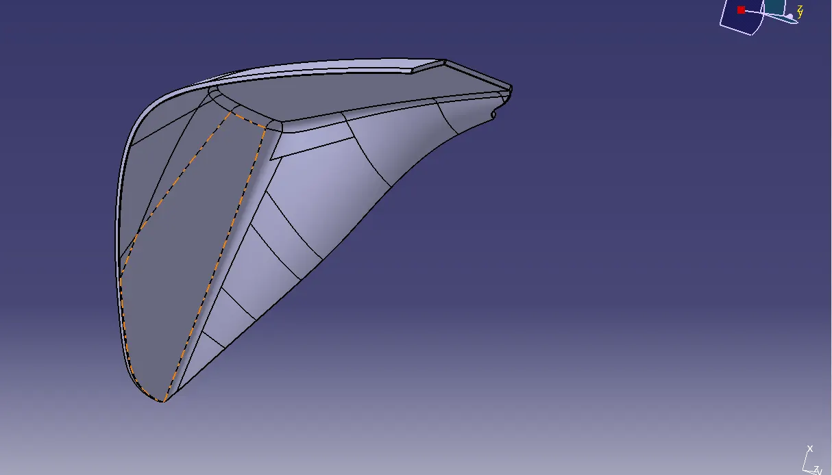
- Now make solid body out of this surface which could be known as Class B-surface as shown:
- Draft analysis on closed body:
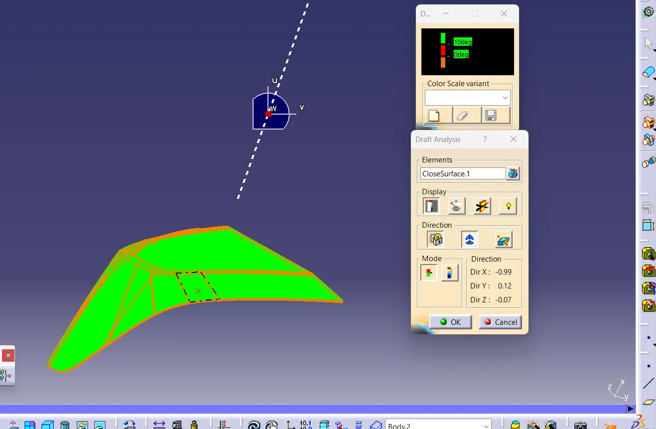
Ans5: Report on the creation of a parting line on the thickened lens and approach on draft analysis as shown:
Aim: To create the parting line on the thickened lens and approach of draft analysis on it.
Given: Draft analysis inputs:
and
given class A surface:
Report:
- A parting line is an imaginary line formed due to the intersection of the core and cavity parts of a mold due create proper injection moulding shown:
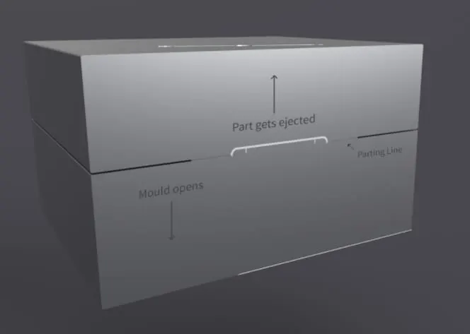
- By creating the close boundary around the class A surface which could be considered as a parting line as shown:
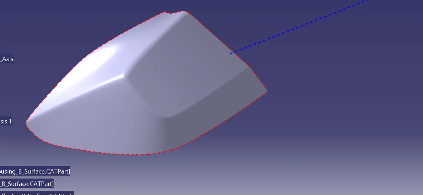
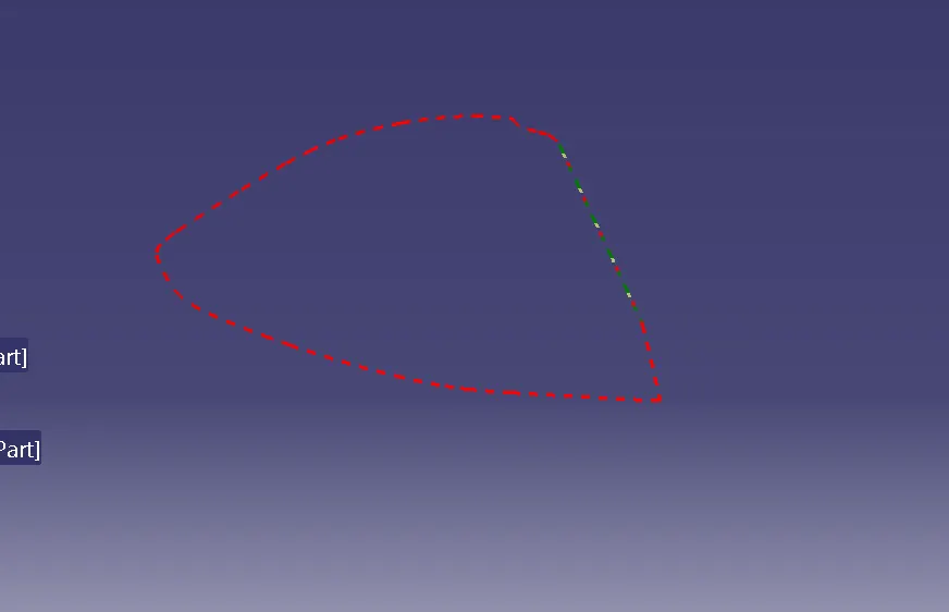
- Parting line:
- After doing the draft analysis on the material view mode of the solid model we get the result as shown:
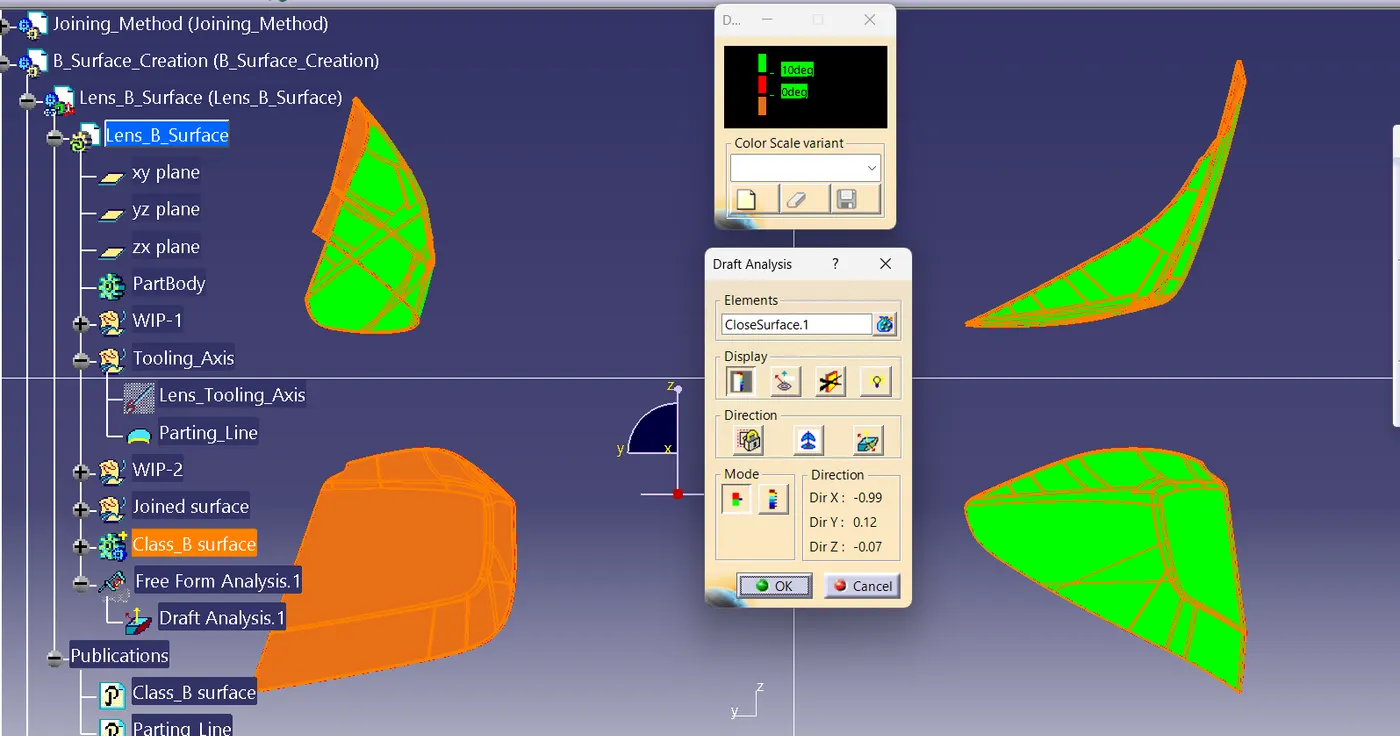
- We can clearly see there is a separation between the Class A and ClassB and C surfaces by a dotted line in red colour which is known as parting line, also green color indicates that part is correct with the tooling point of view as it's clearing the draft.
- So our final model is: