Week 4 Challenge
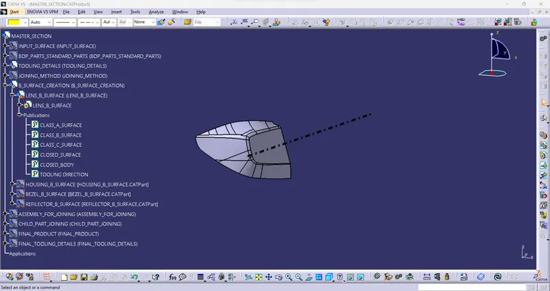
TOOLING_DIRECTION:
- Tooling direction is the main consideration for plastic parts and mold parts because it defines the movement of the mold part and the possibility of the plastic part coming out from the mold part (Core and Cavity).
- In Molding, machine arrangement is given to open the mold along a direction which is known as Tooling Direction.
- The mold is built from two separate halves (Core and Cavity) and the tooling direction basically defines the direction of the mold pulls apart. Tooling direction is known as primary direction.
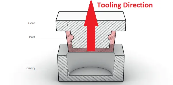
Tooling direction for lens:
Draft Analysis:
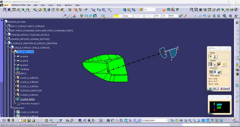
- The Draft Analysis allows the user to easily analyze a part for a proper draft angle. A Draft Angle describes the amount of taper for molded or cast parts perpendicular to the parting line.
- The draft analysis technique is used to analyze whether our part model created in CAD is manufacturable based on the draft condition applied. Here the part should get easily removed from the panel dies (in case of Sheet metal part) or Mold (in case of plastic).
- No parts can be ejected from the tool if it is having a straight 90-degree profile from its base surface. A small draft angle is provided to each and every area of the component in order to get easy removal of the component from the tool.
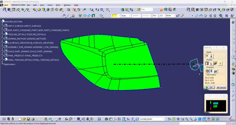
- Here we are providing a direction in which components should eject in order to get easy removal of components from the tool. In other words, it also lets us know whether the model has a draft angle and how much the draft angle is from the tool direction.
DRAFT ANALYSIS FOR 10°:
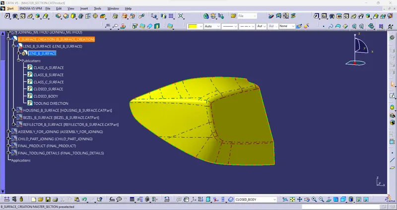
CLASS A SURFACE:
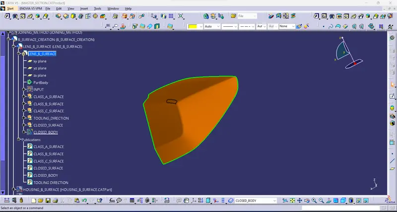
CLASS B SURFACE:
- To offset the input surface for 4 mm to create the class B surface.
- To close the little patch using multiple surfaces.
- To get a complete class B surface.
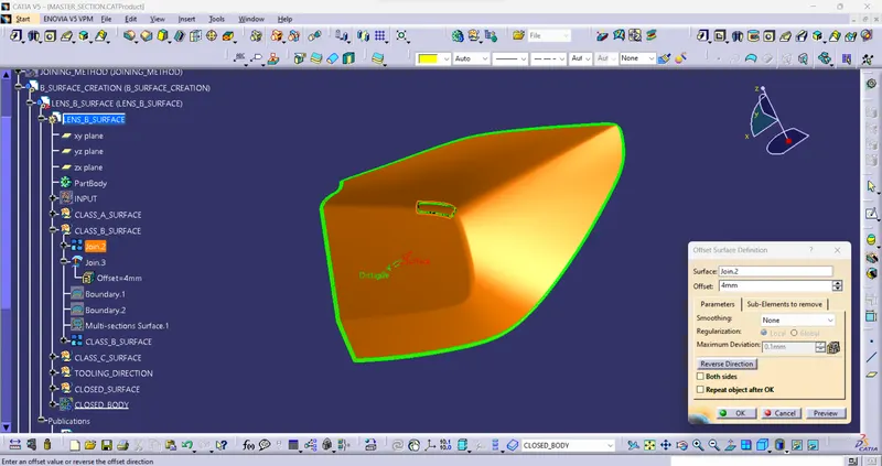
CLASS C SURFACE:
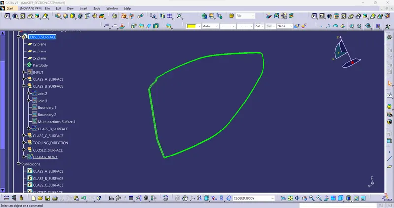
CLOSED SURFACE:
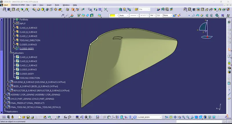
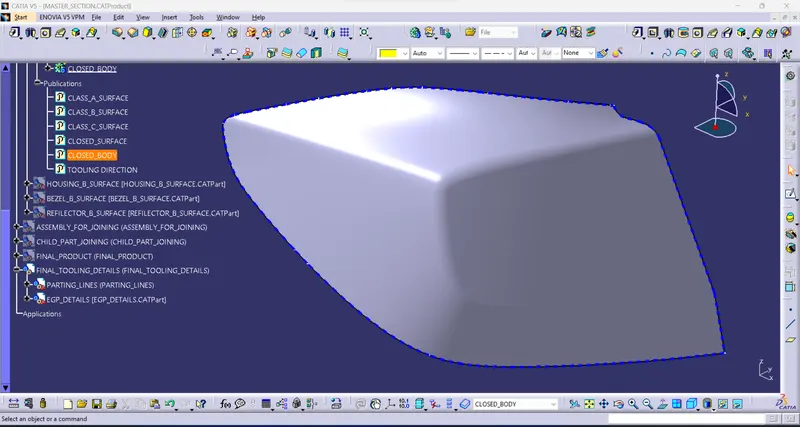
CLOSED BODY:

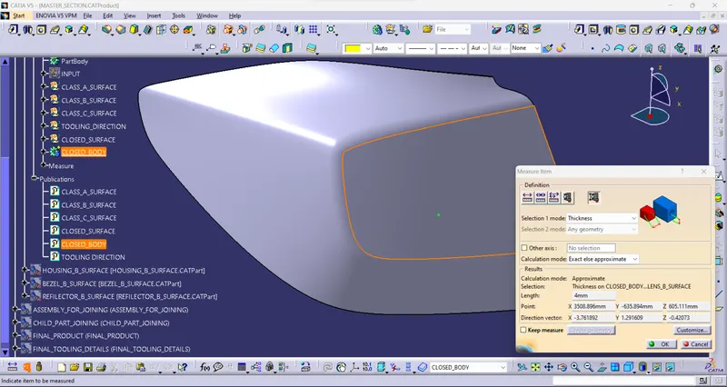
PARTING LINE:
- A parting line is an inevitable part of injection-molded products. It is the line of separation between where two halves of a mold meet. It manifests itself on injection molded parts as a line that runs the entire perimeter of the part. In most parts, it is just a line that runs straight down the middle.
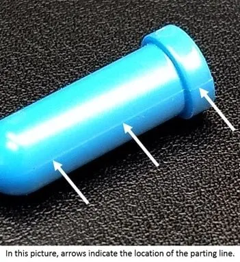
Types of Parting Line in Injection Molding
There are different forms of parting lines depending on the design of the injection mold or plastic parts.
- Vertical parting line: it is formed in a perpendicular direction from the mold opening direction.
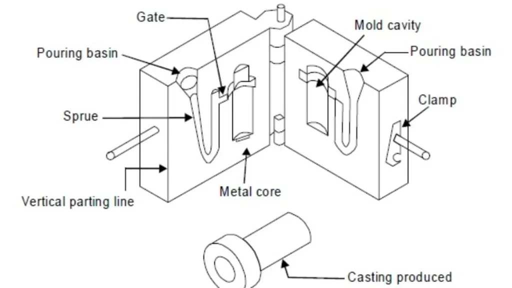
- Beveled parting line: as the name implies, the shape of the parting line is beveled.
- Curved parting line: as the name implies, the shape of the parting line is curved.
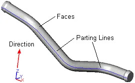
- Stepped parting line: machinists make the plastic parting line in a stepped shape. For this type of parting line, there is usually a large force on one side of the cavity. This leads to the possibility of relative sliding between the fixed and moving halves of the die. This force can then be offset by creating an injection force on both sides of the cavity.
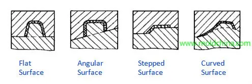
- Comprehensive parting line: designed based on the structure of the plastic part, it can combine all other parting line forms.
PARTING LINE FOR LENS COMPONENT: