Week 4 Challenge
DESIGN OF LENS
OBJECTIVE: The objectives of the challenge are as given below,
- To know about tooling direction.
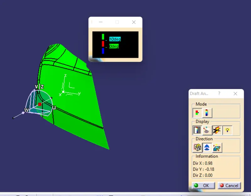
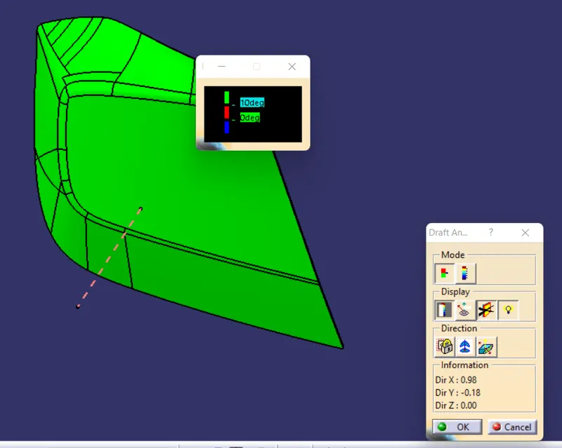
- To create a tooling direction for given classA surface with 10 degree draft and performing draft analysis on classA.
- To know about Parting line.
- To create a classB surface with 4mm thickness.
- Creating a parting line for the thickened part.
- Preparing a report by attaching all the relevant images.
1. TOOLING DIRECTION OR AXIS:
The Tooling Direction is basically the direction that the mold pulls apart. The mold is built in two separate pieces, basically. You have a Cavity side and you have the Core side. The Core pulls apart from the Cavity and that's the Dyeline or the Tooling Direction.
And the axis which represents the tooling direction is called tooling axis and selection of this is axis is a crucial step while performing the draft analysis.
2.CREATION OF TOOLING AXIS:
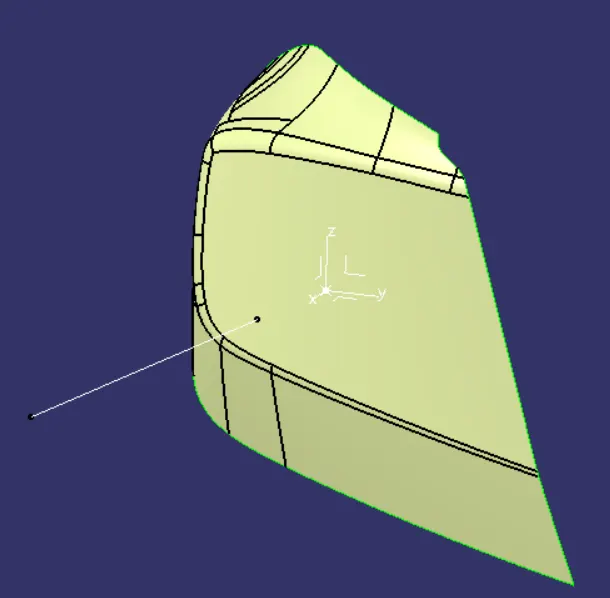
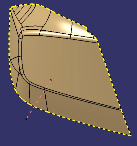
1. Extract the given Class A surface
2. Create a Point.
3. Now create a tooling line with which can satisfy 10 Degree draft.
DRAFT ANALYSIS ON CLASS A:
The draft analysis on the class A surface has been performed with the tooling axis which is created and the images are attached below,
3. PARTING LINE:
A parting line is an inevitable part of injection molded products. It is the line of separation between where two halves of a mold meet. It manifests itself on injection molded parts as a line that runs the entire perimeter of the part. In most parts, it is just a line that runs straight down the middle. However, in more complex parts, its location varies.
While a parting line might seem harmless, it is very important in determining the usefulness of a part. This is because its position is influential in helping designers and molders to decide where to insert other features of the part. If a machinist places an important feature on the wrong side of the parting line, it could lead to serious issues with the whole injection molding process.
4. CREATION OF CLASS B SURFACE:
1. Extract class A surface
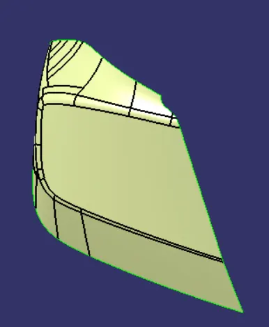
2. Offset the class A surface to the required distance
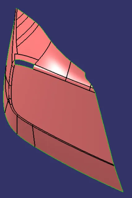
3. Repair the surface if required.
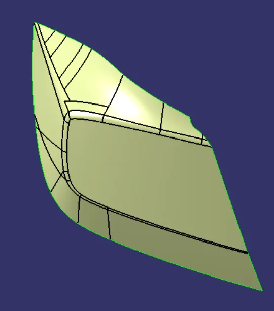
4. Join all the surfaces and rename the surface and publish it.
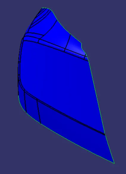
6. Create a class C surface by using blend and sweep commands. For sweep use the tooling direction which is created earlier.
7.Join Class A and Class C surfaces and trim them with class B to make a closed surface of lens. If required extrapolate the classB surface.
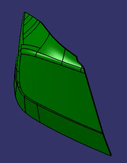
8. Now by using close surface option in part workbench, create a solid body of LENS.
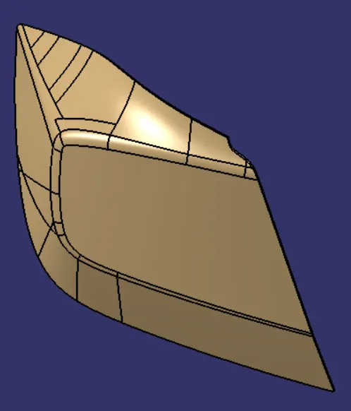
5. CREATION OF PARTING LINE AND PERFORMING DRAFT ANALYSIS ON SOLID BODY:
1. Extract the edges on the class A side of the closed body and that will make the parting line of the lens and publish it.
2. Now finally perform the draft analysis on the class A surface and check the draft.
ISO_VIEW:
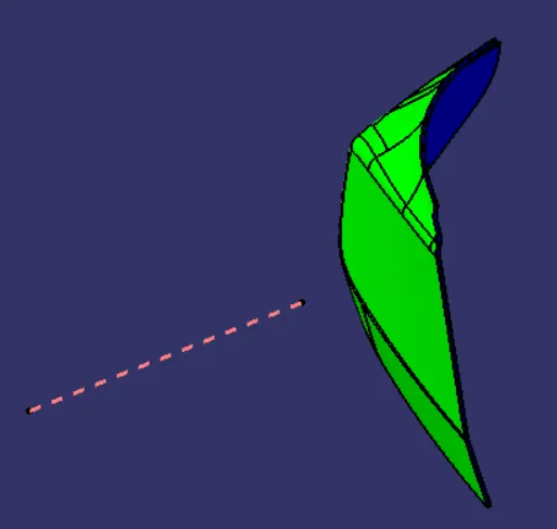
FRONT_VIEW:
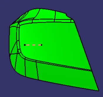
SIDE_VIEW:
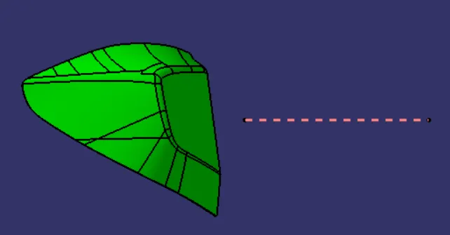
TOP_VIEW:
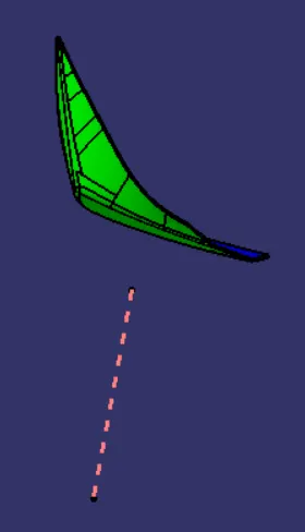
BACK_VIEW:
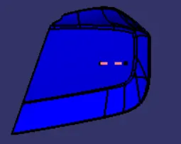
CONCLUSSION: And hence all the objectives of the challenge has been accomplished and a detailed report has been prepared successfully.