Week 4 Challenge
CHALLENGE 4
Aim: The main aim of this challenge is to gain the knowledge about the concept of design of a laterally restrained and laterally unrestrained beam when subjected to the loading is understood and the various parameters that are to be taken into consideration while designing of a beam. And to determine the sizes that are required for the beam to taken up the both bending moment and the shear force is also learnt. The design concept for the purlin is also learnt.
Introduction: One of the frequently used structural members is a beam whose main function is to transfer load principally by means of flexural or bending action. • In a structural framework, it forms the main horizontal member spanning between adjacent columns or as a secondary member transmitting floor loading to the main beams. • Normally only bending effects are predominant in a beam except in special cases such as crane girders, where effects of torsion in addition to bending have to be specifically considered.
Laterally supported beam: When the lateral support to the compression flange is adequate, the lateral buckling of the beam is prevented and the section flexural strength of the beam can be developed. The strength of I-sections depends upon the width to thickness ratio of the compression flange. When the width to thickness ratio is sufficiently small, the beam can be fully plasticised and reach the plastic moment, such sections are classified as compact sections. However provided the section can also sustain the moment during the additional plastic hinge rotation till the failure mechanism is formed. Such sections are referred to as plastic sections.
When the compression flange width to thickness ratio is larger, the compression flange may buckle locally before the complete plasticisation of the section occurs and the plastic moment is reached. Such sections are referred to as non-compact sections. When the width to thickness ratio of the compression flange is sufficiently large, local buckling of compression flange may occur even before extreme fibre yields. Such sections are referred to as slender sections.
Laterally unsupported beams: Under increasing transverse loads, a beam should attain its full plastic moment capacity.
Two important assumptions have been made therein to achieve the ideal beam behaviour. They are:
- The compression flange of the beam is restrained from moving laterally; and
- Any form of local buckling is prevented.
Web buckling:
- Web buckling occurs when intensity of compressive stress near the center of the section exceeds the critical buckling stress of web acting as a strut.
- At supports and under a concentrated load, certain portion of the beam acts as a column to transfer the load.
- Under this compressive force the web of the beam section may buckle.
- The load dispersion angle may be taken as 45 degrees.
- Hence the section should be checked for web buckling.
- The rolled sections are provided with suitable thickness for web so that web buckling is avoided.
- The probability of web buckling is more in the case of built- up sections having greater ratio of depth to thickness of the web.
- At the point of concentrated load web may be considered as a strut between the beam flanges.
- The load is assumed to disperse over the length of (b,+n,)., where (b,) is the stiff bearing length and (n,) is the dispersion of the load through the web at 45 degrees, to the level of half the depth of cross-section.
- In case of built-up sections, it is necessary to check for buckling of web and provide web stiffeners.
- Effective web buckling strength is to be found based on the cross-section of web [(b,+n,)tw].
- Fcdw = [(b,+n,)t,]f.
- Fcdw = Web buckling strength
- = allowable compressive strength corresponding to the assumed web column corresponding to its slenderness ratio and effective length.
- Effective length= 0.7d
- d= depth of the strut between the flanges= =[Total depth- 2*(tr + R1)]
- radius of gyration = r, = S(l,/A) = t/(2/3)
- slenderness ratio = 0.7d/r, = 2.42d/tw
Web crippling:
- Concentrated loads and reactions are resisted by compressive stresses in the web of steel beams.
- Therefore web is acted upon by large amount of stresses at these locations.
- Stress concentration occurs at the junction of the web and the flange, as a result large bearing stresses are developed. At these locations, web tends to fold over the flange.
- This type of local buckling is called as web crippling.
- Web crippling is the buckling of the web due to the compressive force delivered through the flange.
- So, the concentrated load should be transferred from flanges to the web on sufficiently large bearing areas.
- The root of the fillet is the most critical location for failure.
- In the case of web crippling at a support, the crippling strength of the web is given by: Fw = (b1+n2)twfyw/Tm0
- Where b1= stiff bearing length; fyw = yield strength of web
- n2 = dispersion length through the flange to the web junction at a slope of 1:2.5 to the plane of flange.
- At the point of application of a concentrated load,
- Fw = (b1+2n:)twfyw/Tmo
- Since the dispersion of the load takes place on either side.
Design of Beams
- Section classification problem for listed beam shapes
Calculate section classification of following beam shapes
ISMB 500
ISMC 200
PG 1300 x 450 x 20 x 12
Double angle (Back to back) – 2 x ISA 75x75x6
RHS - 150 x 100 x10
Builtup box – 1000 x 450 x 20 x 12
Ans: From the steel table for ISMB 500 the data are given below
Depth of section (D) = 500mm
Width of the flange (b) = 180mm
Thickness of the flange (tf) = 17.2mm
Thickness of the web (tw)= 10.2mm
b/tf = 180/17.2 = 10.46 < 10.5
Thus it is a Compact section
- From the steel table for ISMC 200 the data are given below
Depth of section (D) = 200mm
Width of the flange (b) = 75mm
Thickness of the flange (tf) = 11.4mm
Thickness of the web (tw)= 6.1mm
b/tf = 75/11.4 = 6.57 < 8.4
Thus it is a Plastic section
- For the member given in figure
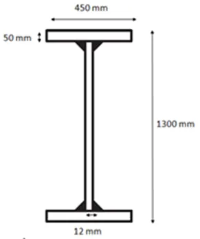
Depth of section (D) = 1300mm
Width of the flange (b) = 450mm
Thickness of the flange (tf) = 50mm
Thickness of the web (tw)= 12mm
b/tf = 450/50 = 9< 9.4
Thus it is a Plastic section
- For double angle 2 x ISA 75x75x6
Section size (b) = 75mm
Thickness of the flange (tf) = 6mm
b/tf = 75/6 = 12.5< 15.7
Thus it is a Semi-Compact section
- For RHS 150x100x10 the data are given below
Depth of section (D) = 150mm
Width of the section (b) = 100mm
Thickness = 10mm
Along X-X direction
b/tf = 100/10= 10 < 10.5
Thus it is a Compact section
Along Y-Y direction
b/tf = 150/10= 15 < 15.7
Thus it is a Semi - Compact section
- For the section given in figure
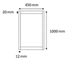
Depth of section (D) = 1000mm
Width of the section (b) = 450mm
Thickness (tf) = 20mm
Thickness (tw) = 12mm
b/tf = 1000/12= 83.35 < 84
Thus it is a Plastic section
- Effective length problems
Calculate effective length of rafter made up of Builtup I section about major (x-x) and minor axis (y-y) having purlin spaced at 1.2 m.
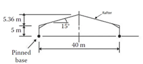
Ans: Effective length of the top chord 1 = 0.85L1
Effective length of the top chord 2 = 0.85L2
Effective length of the vertical member = 0.85L3
Effective length of the inclined member = 0.75L4
Effective length of the rafter= 0.85L
Length of the rafter = 20/cos15 = 20.7m
Therefore, effective length = 0.85*20.7 = 17.6m
- Deflection of a beam problem
- Calculate deflection at the centre of the beam shown below. EI = 20 x 106 Nm2
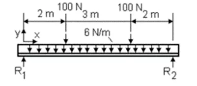
Ans: Deflection of the member above is calculated as follows:
Deflection = (5wl^3/384EI)+(wl^3)/48EI*((3a1)/l-4(a1/l)^3)+(wl^3)/48EI*((3a2)/l-4(a2/l)^3)
=(5*6*7^3)/(384*20*10^6)+(100*7^3)/(48*20*10^6)*(3*2)/7–4(2/7)^3)+ 100*7^3)*(3*5)/7 – 4*(5/7)^3)
=1.339*10^-6+2.7*10^-5+2.43*10^-5m
=0.0527mm
- Calculate deflection at the centre of the beam shown below. EI = 25 x 106 Nm2
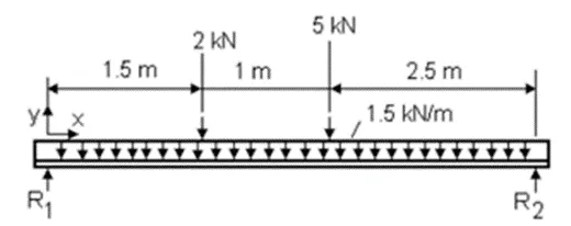
Deflection of the member above is calculated as follows:
Deflection = (5wl^3/384EI)+(wl^3)/48EI*((3a1)/l-4(a1/l)^3)+(wl^3)/48EI*((3a2)/l-4(a2/l)^3)
=(5*1500*5^3)/(384*25*10^6)+(2000*1.5^3)/(48*25*10^6)*(3*1.5)/5–4(1.5/5)^3)+ (5000*5^3)/(48*25*10^6)*(3*2.5)/5 – 4*(2.5/5)^3)
=9.76*10^-5+1.65*10^-4+5.208*10^-4
=0.783mm
- A simply supported beam is 10 m long with udl of 10 kN/m Calculate the Flexural stiffness (EI) of the beam which limits the deflection to 5 mm at the middle
Ans: Deflection for simply supported beam is given by = (5wl^3)/(384EI)
EI = (5wl^3)/(384*deflection)
EI = (5*10*1000*10^3)/(384*5*1000)
=26.04N/m2
- Moment capacity determination problem
Select a standard hot rolled section for the beam which is simply supported of length 6 m spaced at 3 m c/c, carrying a floor Dead load of 5 kN/m2 (including Self weight) & Live load of 6 kN/m2 and a concentrated load of 100 kN at mid span of beam. The beam is laterally restrained and assumes bearing length of 50 mm.
Ans: Given: Dead load = 5kN/m2
Live load = 6kN/m2
Total load = 5+6 = 11kN/m2
The beam is spaced at 3m c/c thus the load = 11*3 = 33kN/m
The maximum bending moment = BM due to UDL+BM due to concentrated load
=(wl2)/8+(wl)/4
=(33*6*6)/8+(100*6)/4
=298.5kNm
Plastic modulus Zp(required) = (M*γm0)/fy
=298.5*10^6*1.1/250
=1313.4*10^3m3
Let us adopt ISMB 500 with section modulus of 1808.7*10^3m3
Properties of ISMB 500
Depth (d) = 500mm
Width of the flange (b) = 180mm
Thickness of flange (tf) = 17.2mm
Thickness of web (tw) = 10.2mm
Depth of the web (h) = 500-2*17.2 = 465.6mm
Section classification
b/tf = 180/17.2 = 10.46<10.5
Thus the section is compact section
Calculation of shear force
Shear force = 100+33*6 = 298kN
Reaction = 298/2 = 149kN
Design shear strength Vd = (fy*d*tw)/(γm0√3)
= (250*500*10.2)/(1.1*√3)
=669.2kN
0.6Vd = 0.6*669.2 = 401.52kN
149<401.52kN
Design capacity Md = βp*Zb*fy/γm0<1.2*Ze*fy/1.1
Βp = 1 for compact section
=(1*1313.4*250)/1.1<1.2*1808.7*250/1.1
= 298.5kN-m<493.28kN-m
Hence it is ok
Check for deflection
Max deflection = 5wl^3/384EI+wl^3/(48EI)
=(5*33*10^3*6000^3)/(384*2*10^5*45218.3*10^4)+(100*10^3*3000^3)/(48*2*10^5*45218.3*10^4)
=1.026+0.62 = 1.64mm
Deflection due to load
= span/300 = 6000/300 = 20mm
1.64<20mm
Hence it is ok
Check for web buckling
Assume stiffener plate of width b1 = 50mm
Ieff of web =(b1*tw^3)/12
= (50*10.2^3)/12
= 4421.7mm
Area of the web = 50*10.2 = 510mm2
Radius of gyration = sqrt(I/A)
= √(4421.7/510)
r= 2.9mm
Effective length of the web = 0.7*depth of the web
=0.7*465.6
d(effective)= 325.92mm
λ = d(effective)/r
=325.92/2.9 = 112.38
For λ and fy 250 from IS 800-2007 we get
Fcd= 83.7Mpa
Check for web buckling
n1 = 500/2 = 250mm
b1+n1 = 50+250 = 300mm
Fwb = (b1+n1) *tw*fcd
= 300*10.2*83.7
= 256.12kN<669.2kN
Hence it is safe
Check for web crippling
F(crippling) = (b1+n2)*t*fy/γm0
n2=2.5d1 = 2.5*465.6 = 1164mm
F(crippling) = (50+625)*10.2*250/1.1
=569.12<669.2kN
Hence it is safe.
- Purlin design problem
Design channel purlin, considering sag rod at mid span for the roof truss having following data
Span of truss : 20 m
Spacing of Truss : 4 m c/c
Roof slope : 20 degrees
Spacing of purlin : 2 m
Wind suction : 1 kN/m2
Live Load : 0.75 kN/m2 ,Dead Load 1.4 kN/m2
Ans: Total load = DL+LL = 0.75+1.4 = 2.15kN/m2 = 2.15*2 = 4.3kN/m
Factored load = 4.3*1.5 = 6.45kN/m
Load acting parallel = wsinө = 6.45*sin20 = 2.2kN/m
Load acting moment = wcosө = 6.45*cos20 = 6.06kN/m
Factored wind load = 1.5*1*spacing of purlin = 1.5*1*2 = 3kN/m
Total load moment = 6.06+3 = 9.06kN/m
Total load parallel = 2.2kN/m
Moment along Z-Z axis = wl2/8 = 9.06*4^2/8 = 18.12kNm
Moment along X-X axis = wl2/8 = 2.2*4^2/8 = 4.4kNm
Adopt the width as 75mm and depth as 190mm
Zpz = Mz (γmo/fy)+2.5*(d/b)(My*(γmo/fy)
= (18.12*10^6*1.1)/250 + 2.5*190*4.4*10^6*1.1)/(75*250)
=93.18*10^3mm3
Adopt ISMC 150
Zrz= 103.9*10^3mm3
Width of the flange = 75mm
Thickness of the flange = 9mm
Thickness of web = 5.4mm
Zyy = 19.4*10^3mm3
E = (250/b)^1/2
=(250/75)^0.5 = 1.82
b/tf = 37.5/9 = 4.16<9.46
h = D-2tf
=150-2*9= 132mm
d/tw = 132/5.4 = 24.44<54
Hence, the section is plastic section
Mdz = Zpz*fy/γm0 = 103.9*10^3*450/1.1 = 42.5kN/m
Mdy = Zpy*fy/γm0 = 19.4*10^3*450/1.1 = 7.9kN/m
Check
Mz/Mdz + My/Mdy <1
18.12/42.5 + 4.4/7.9 = 0.97<1
Hence it is ok
Check for deflection
Deflection = span/180
=4000/180 = 22.22mm
Deflection due to load = (5wl^3)/(384EI)
= (5*6.45*4000^3)/(384*2*10^5*0.779*10^4)
=3.44mm<22.22mm
Hence ok
Thus adopt ISMC 150 section for purlin.
Conclusion:
From the project carried out it can be concluded that the concept of the design procedure of the beam when it is laterally restrained and laterally unrestrained is learnt and the various reasons for the failure of the beam member is learnt. The design concept of the purlin is also learnt. The method for the determination of the size of the beam when subjected to the loading is also learnt.
Vijayalakshmi S H