Week-4 : Basic Calibration of Single cylinder CI-Engine
AIM: Basic Calibration of Single-cylinder CI-Engine
OBJECTIVE:
1. Compare SI vs CI and list down differences (assignment no 2-SI)
2. Comments on the following parameters
- BSFC
- Exhaust Temperature
- A/F ratios
3. Change MFB 50 and observe the impact on performance
SI engine (Spark Ignition Engine)
spark from a spark plug to initiate the ignition. SI engine works based on the OTTO cycle. The air-fuel mixture is done by the carburetor and injected the mixture into the engine cylinder for combustion.
A spark plug then generates a spark to start burning the air-fuel mixture. Since there is no such compression of air to initiate the burning of fuel-air mixtures, SI engines usually have a low compression ratio. And that is why SI engines are less powerful too.
During a suction stroke, the carburetor supplies the air-fuel mixture to the engine unlike CI engines where only the air is sucked during a suction stroke
SI engines are also lightweight and simple in design. It produces less noise and vibration. The maintenance cost of the SI engine is low compared to CI engines. SI engines are mostly used in light commercial vehicles like passenger cars, scooters, etc
CI Engine ( Compression Ignition Engine )
based on the diesel cycle. CI Engine does not use any carburetor for mixing air and fuel. Instead, the air is sucked during suction stroke, and it is pressurized to be heated. When the air is pressurized enough, fuel is injected through fuel injectors. The heat of the highly compressed air starts the ignition.
Since excessive pressure is required to compress the air, diesel engines have high compression ratios than any other SI engines. Also, the noise and vibration are more in CI engines.
There is no spark plug for the timely initiation of a spark in the CI engine, and there is always a chance of incomplete combustion of fuel. Due to incomplete combustion, more hydrocarbons are generated, which is causing air pollution.
CI engines are complex in design and usually costly. Maintenance is also not easy. Usually, heavy vehicles like trucks, buses, ships, etc., use CI engines
Difference b/w SI and CI engine.
|
SI Engine |
CI Engine |
|
SI engine uses a spark plug to initiate ignition |
CI Engine does not have any spark plug |
|
Spark is initiated by the spark plug |
Spark is initiated by the heat of compressed air |
|
Petrol is the fuel |
Diesel is the fuel |
|
Based on Otto Cycle |
Based on the diesel cycle |
|
Constant volume heat addition |
Constant pressure heat addition |
|
The carburetor supplies the fuel |
Fuel injectors supply the fuel |
|
During suction stroke, the air-fuel mixture is sucked |
Only Air is sucked during suction stroke |
|
The compression ratio varies between 6-10 |
The compression ratio varies between 16-20 |
|
Less production of hydrocarbon |
High production of hydrocarbon |
|
Simple design compared to CI engine |
Complex design |
|
Low thermal efficiency due to the low compression ratio |
High thermal efficiency |
|
Low pressure is generated after combustion |
High pressure is generated after combustion |
|
The volume to-power ration is low |
The volume to-power ration is high |
|
Produce little noise |
Produce too much noise |
|
Maintenance is easy |
Maintenance is tough |
|
Weight is less |
Weight is more compared to SI engine |
|
SI engines are high-speed engines |
CI engines are low-speed engines |
|
Very less vibration problem |
Vibration is common in CI engines |
|
The starting of the engine is easy |
Starting the engine is difficult, especially during winters |
|
Used in small to medium-sized vehicle |
Used in heavy vehicles |
|
Usually cheaper than the CI engine |
CI engines are costly |
Exploring the Tutorial of Single Cylinder Diesel Engine:
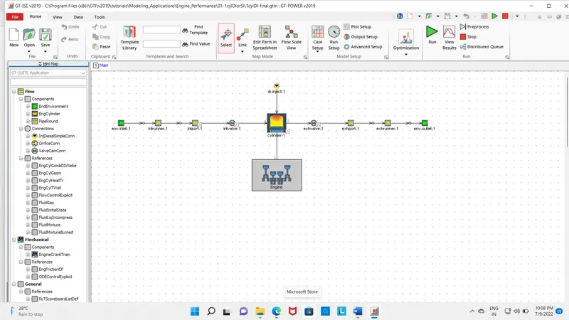
The layout of the 1-cylinder Diesel Injection Engine
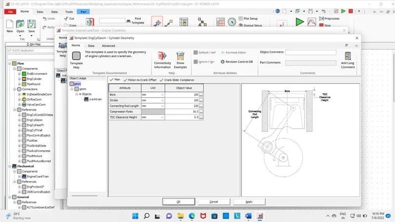
Engine Geometry Template:
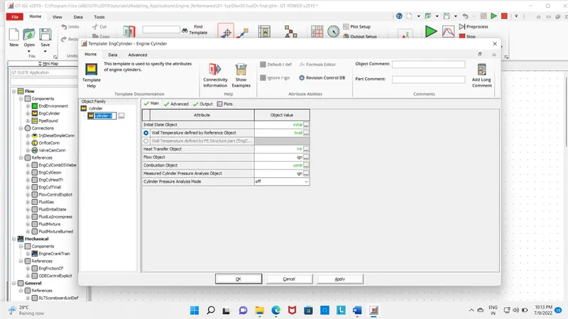
Cylinder Template:
- This part represents the combustion chamber first comes the main tab
Injector Template:
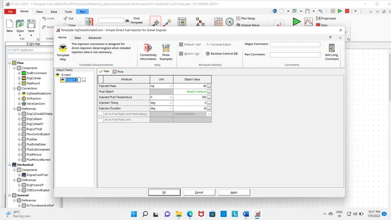
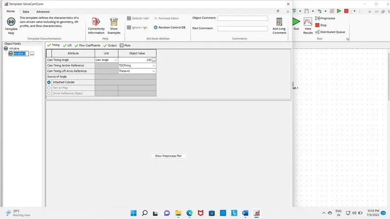
Intake Valve Temperature:
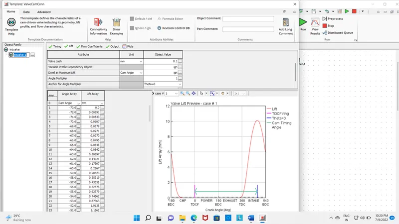
Intake Valve Lift:
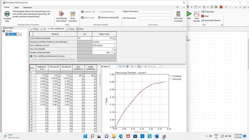
Intake Valve Flow Coefficients:
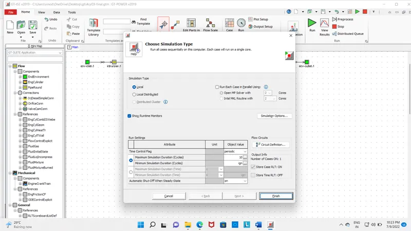
RUN
Engine Performance with 2 different types of Speed:
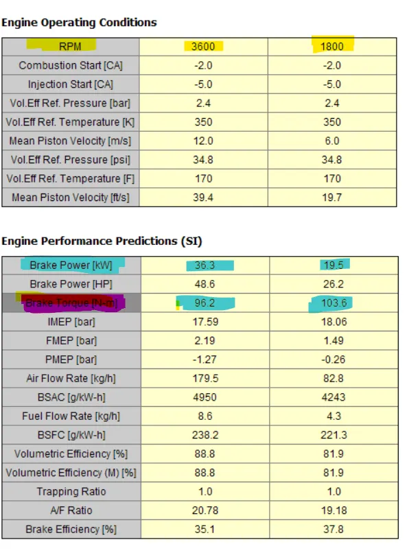
- From the above results, we can clearly have observed that Speed decreases the output of power and also decrease
- The brake power is 96. Hp at a speed of 3600RPM and has shown a tremendous decrease to 48.6 Hp.
- The Brake Specific Fuel Consumption is 221.3 g/kw-h at a speed of 1800 rpm and 238.2 g/kw-h at a speed of 3600. This clearly indicates the rise in the value.
- The air-fuel ratio is also decreased which is also shown in the above image
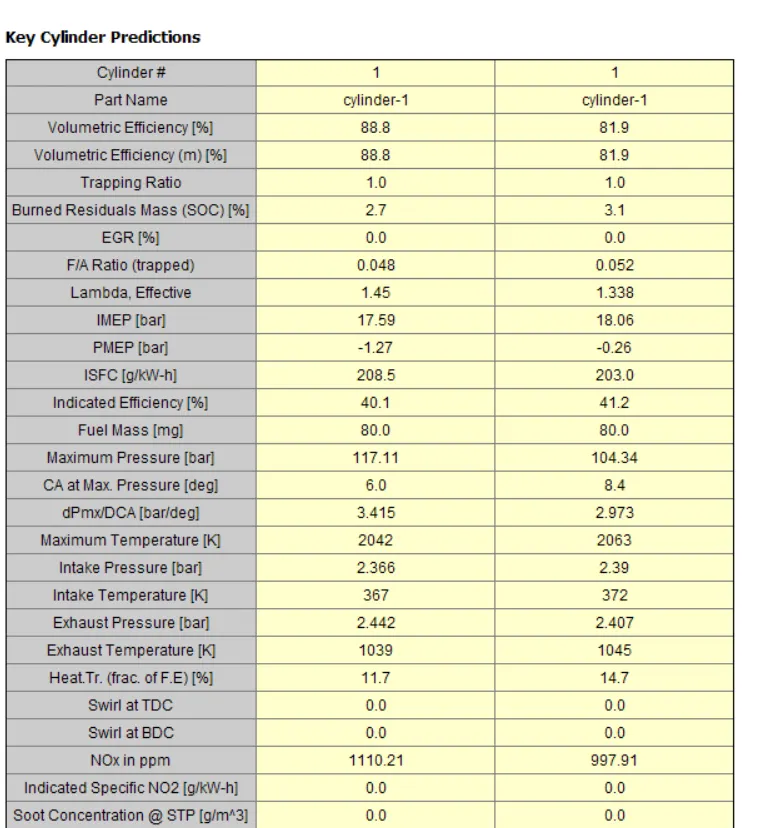
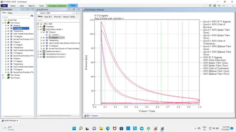
- Maximum inside Cylinder pressure is also decreased from 117.11 bar to 104.34 bar
- Emissions like HC, CO, and CO2 in ppm are greatly reduced with the higher speed.
- The Exhaust temperature is 1045 k with a speed of 1800 RPM and 1039K with a Speed of 3600 RPM
Plots:
Pressure Plot for Both Speeds 1800 and 3600:
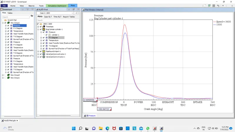
PV Plot for Both Speeds 1800 and 3600:
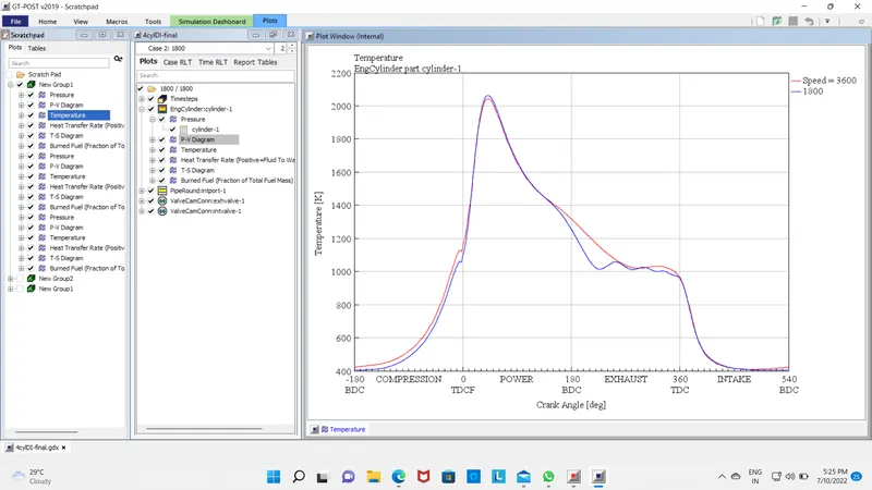
Temperature Plot for Both Speeds 1800 and 3600:
Calibration of SI Engine done:
The block diagram of the SI Engine shows in the below Image:
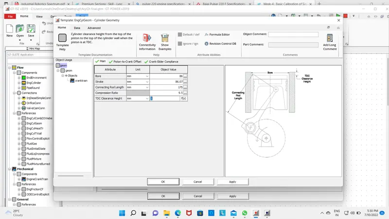
The Geometry Dimensions of the Engine Cylinder:
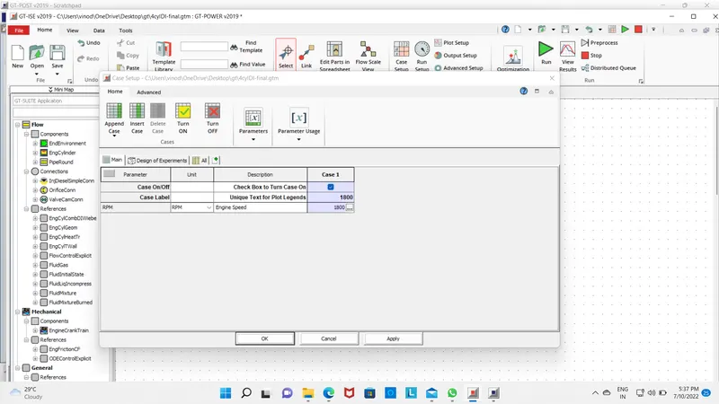
run the case
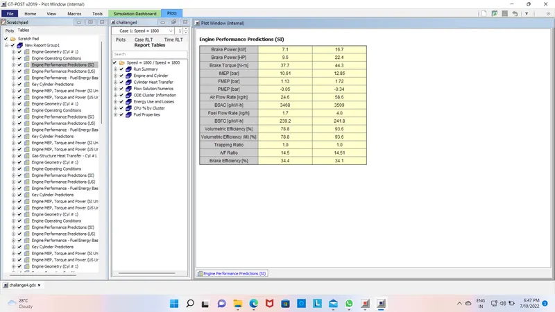
Engine Performance:
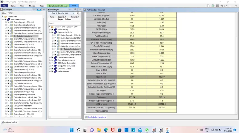
Cylinder Details:
Brake-specific fuel consumption (BSFC):
- Brake-specific fuel consumption(BSFC) is a measure of the fuel efficiency of any prime mover that burns fuel and produces rotational or shaft power. It is typically used for comparing the efficiency of internal combustion engines with a shaft output.
- It is the rate of fuel consumption divided by the power It may also be thought of as power-specific fuel consumption, for this reason. BSFC allows the fuel efficiency of different engines to be directly compared.
- BSFC numbers change a lot for different engine designs, compression ratios, and power ratings. Engines of different classes like diesel and gasoline engines will have very different BSFC numbers, ranging from less than 200 g/(kW⋅h) (diesel at low speed and high torque) to more than 1,000 g/(kW⋅h) (turboprop at low power level).
Exhaust Temperature:
- The temperature of the exhaust gases at the outlet is called Exhaust Temperature.
- The exhaust gases of petrol engines are hotter than the Diesel engine. As a Diesel engine employs a higher Compression ratio and the gas expands more it gets Cooler.
- The diesel engines also operate at a higher Air fuel ratio as there are no throttling losses and hence lower exhaust temperature.
Air Fuel Ratio:
- Air–fuel ratio(AFR) is the mass ratio of air to a solid, liquid, or gaseous fuel present in combustion The combustion may take place in a controlled manner such as in an internal combustion engine or industrial furnace, or may result in an explosion (e.g., a dust explosion, gas or vapor explosion or in a thermobaric weapon).
- The air-fuel ratio determines whether a mixture is combustible at all, how much energy is being released, and how many unwanted pollutants are produced in the reaction. Typically a range of fuel-to-air ratios exists, outside of which ignition will not occur. These are known as the lower and upper explosive limits.
- In an internal combustion engine or industrial furnace, the air-fuel ratio is an important measure for anti-pollution and performance-tuning reasons. If exactly enough air is provided to completely burn all of the fuel, the ratio is known as the stoichiometric mixture, often abbreviated to stoich. Ratios lower than stoichiometric are considered "rich." Rich mixtures are less efficient, but may produce more power and burn cooler. Ratios higher than stoichiometric are considered "lean." Lean mixtures are more efficient but may cause higher temperatures, which can lead to the formation of nitrogen oxides. Some engines are designed with features to allow lean-burn. For precise air-fuel ratio calculations, the oxygen content of combustion air should be specified because of different air densities due to different altitude or intake air temperatures, possible dilution by ambient water vapor, or enrichment by oxygen additions.
Comparison of both SI and CI Engines on the below parameters:
SI engine CI engine
Brake-specific fuel consumption (BSFC):
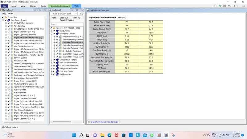
- The Brake Specific Fuel Consumption of the Si engine is high as compared to the CI Engine which means for any given cycle the CI engine has less fuel is consumed.
Exhaust Temperature:
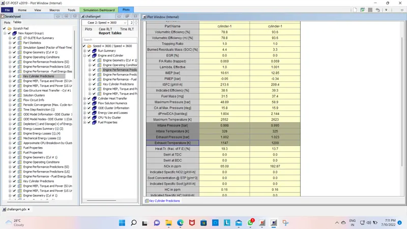
- Due to higher BSFC and complete combustion in SI Engine the exhaust gas temperature is very high in SI engines whereas in Diesel Engine the temperature is very less due to low BSFC.
- SI Engine Exhaust temperature CI Engine Exhaust Temperature
Air Fuel Ratio:
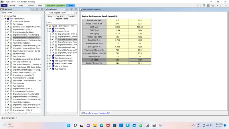
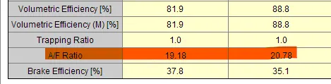
- The Air fuel ratio in CI engines is very high (lean mixture and lean burned) whereas the SI engines have a lower air-fuel ratio (rich burned).
- This is due to the reduction in the compression ratio in SI engines.
- SI Engine Air Fuel Ratio CI Engine Air Fuel Ratio
CI engine
Change MFB 50 and observe the impact on performance:
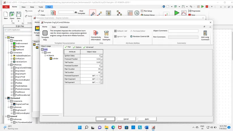
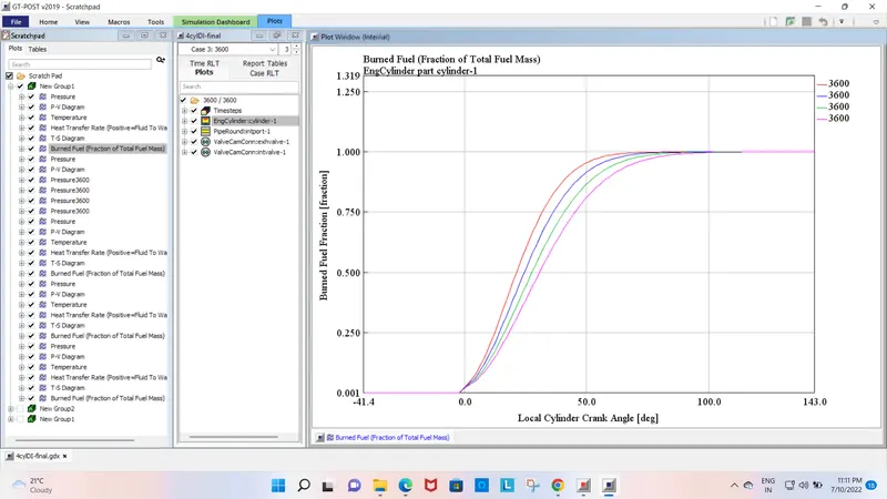
- The mass fraction burned (MFB) shows how the in-cylinder combustion progresses as a function of the crank angle. The rate of combustion inside an engine cylinder is a very important parameter affecting the engine's thermal efficiency, peak cycle temperature and pressure, and exhaust emissions. This combustion rate is usually quantified by calculation of the burn crank angles at which the MFB reaches a specified value
- Combustion Control has always been an important role in the Modern Internal Combustion Engine system and being more crucial nowadays to improve driveability and reduce pollutant emissions. The position where 50% of fuel mass burned over an engine cycle is reached.
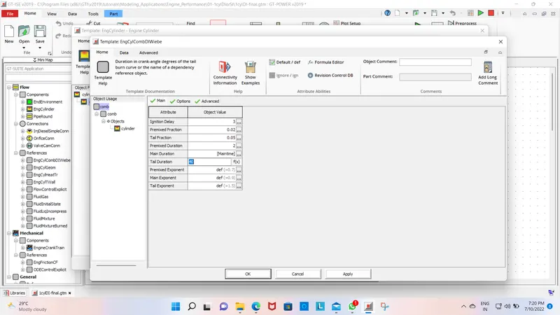
By changing the main duration as parameter performance impact is provided. Duration in crank angle degrees of the main diffusion burn or the name of the dependency reference object.
The block diagram of the CI Engine shows in the below Image:
Cylinder Template:
Case SetUp:
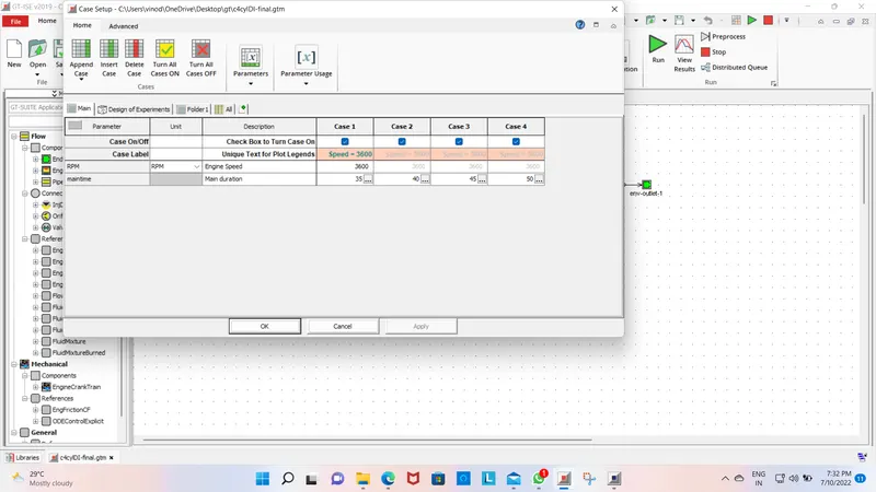
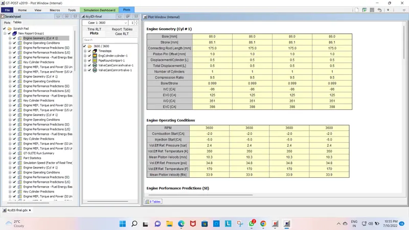
From the above images, we can observe that the Brake power is reduced when we increased the Main duration of the moment of the piston, and also the Torque Power is also reduced and increases in the BSFC when we increase the main duration time.
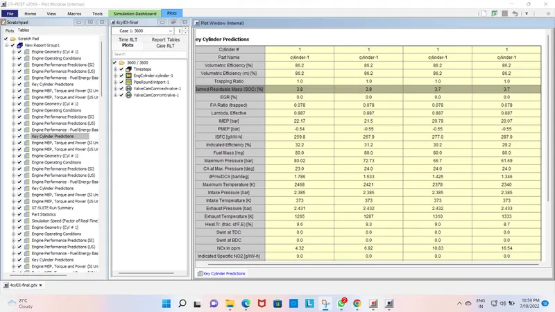
- The CO2 emissions from the engine increase when we increase the Main duration, the CO emissions are up and downs when we changed the values of the main duration.
Graphical Results:
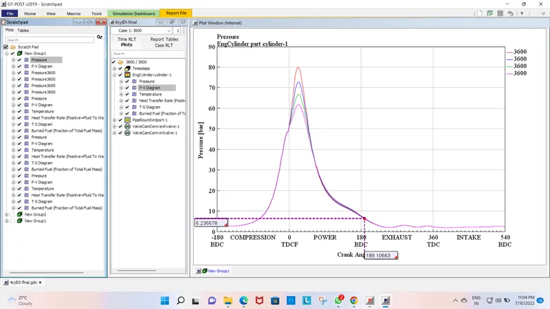
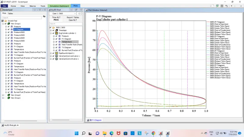
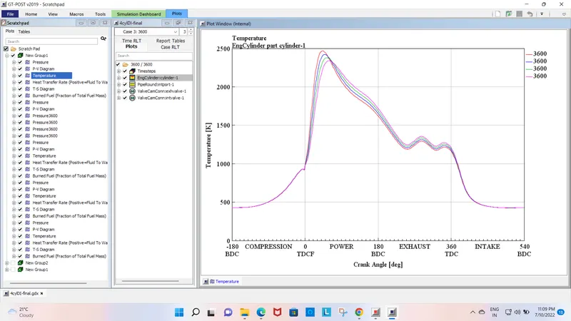
- Graphical results of the MFB50 can be shown below with 35,40,45,50 crank angles with the Speed of 3600 RPM
Pressure Plot:
The crank angle 35 has a high inside cylinder pressure
Pressure _Velocity plot
TEMPERATURE PLOT
BURIED FUEL PLOT
CONCLUSION
The CI engine is run successfully with different speeds and observe the results.
the comparison of the ci and si engine is completed.
The running of the CI engine with the change of main time and observing the results.