Week - 4
- Implement control logic of a “washing machine” using Stateflow as per given sequence:
- If the power supply is available, the system gets activated
- If the Water supply is not available, stop the process & indicate through LED
- Soaking time should be 200s followed by Washing time of 100s.
- Then rinsing happens for next 20s & dryer runs for 50s
After all the processes have completed turn on the finished LED
ANSWER:
AIM:To Implement the control logic of a washing machine by using stateflow
MODEL:
REPORT:
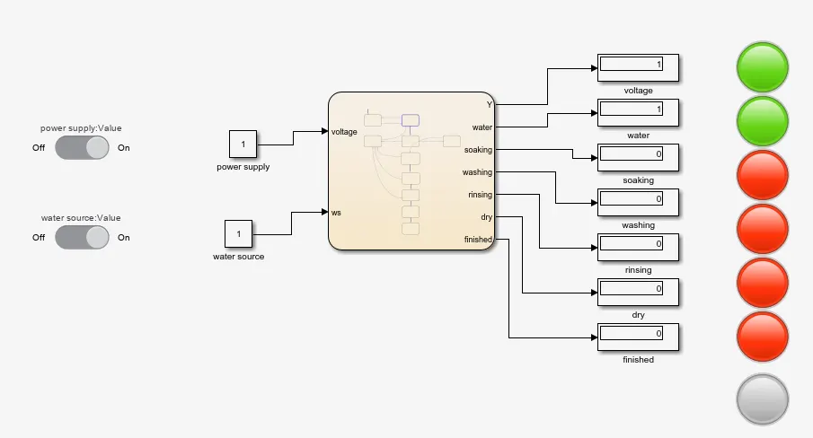
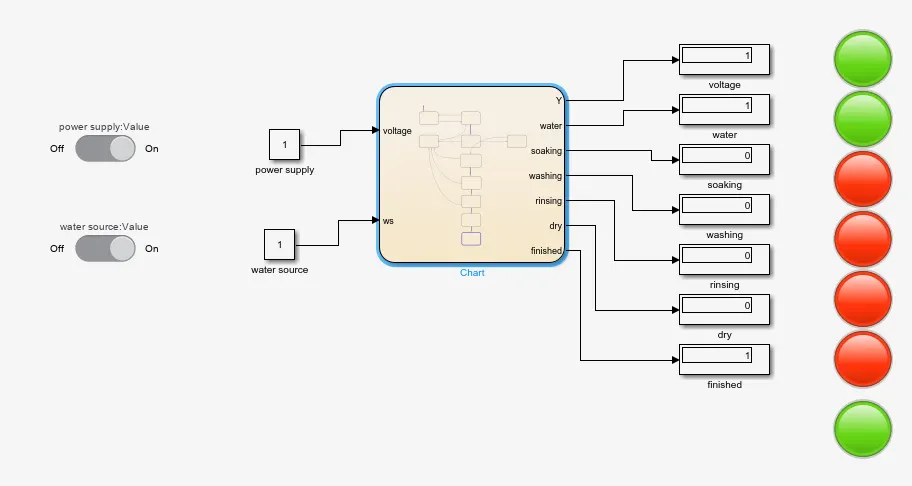
- In this modeling it is a chart flow of washing machine.
- First i have taken the chart model to prepare the chart flow for the washing machine.
- Here there is a two main source that is power supply or source and water source.
- For both of them i have connected with slider switch block , for turn on and off by taking the constant block as shown in model.
- After simulation , To know the value of output ,i have taken the display blocks ,for the output of the model.
- For the indication ,i have taken the lamp block and connected with display block each and every with there respective blocks.
FLOW CHART:
REPORT:
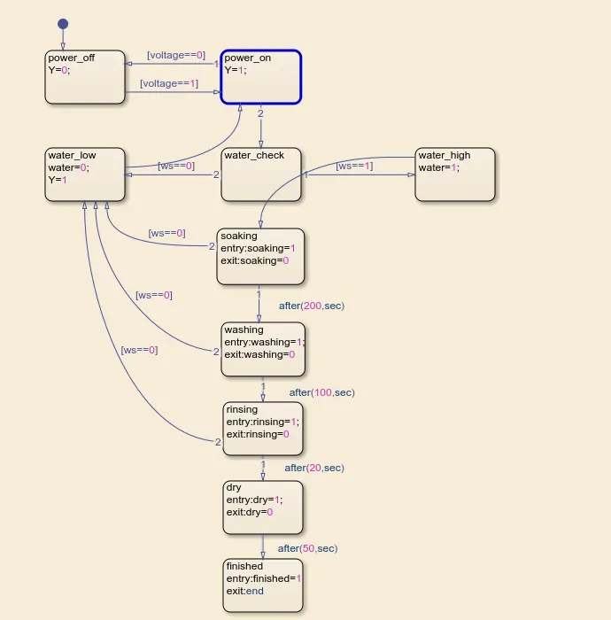
- In this flow chart the voltage is in on state ,the entire flow chart in active state.
- if the power is on ,the flow chart will flow from one state to another state.
- if the water is available ,the flow chart will move to the water_high,elseif the water is not available the it will move to water_low as shown in flow chart.
- while in the middle of the simulation is on washing mode, if sudden water is not availbale the entire process will be stopped and it will shown dark red colour indication on the water lamp.
- Both source are available the it will move to soaking mode after200sec ,it will move to washing mode.
- after 100sec in washing mode ,it will move to rinsing mode after 20sec, it will move to drying mode.
- after 50 sec of drying, its will turn on the finished lamp in a Green colour and the process will be completed.
OUTPUT:
CONDITION 1: IF THE POWER SUPPLY IS AVAILABLE , THE SYSTEM GETS ACTIVATED.
MODEL:
REPORT:
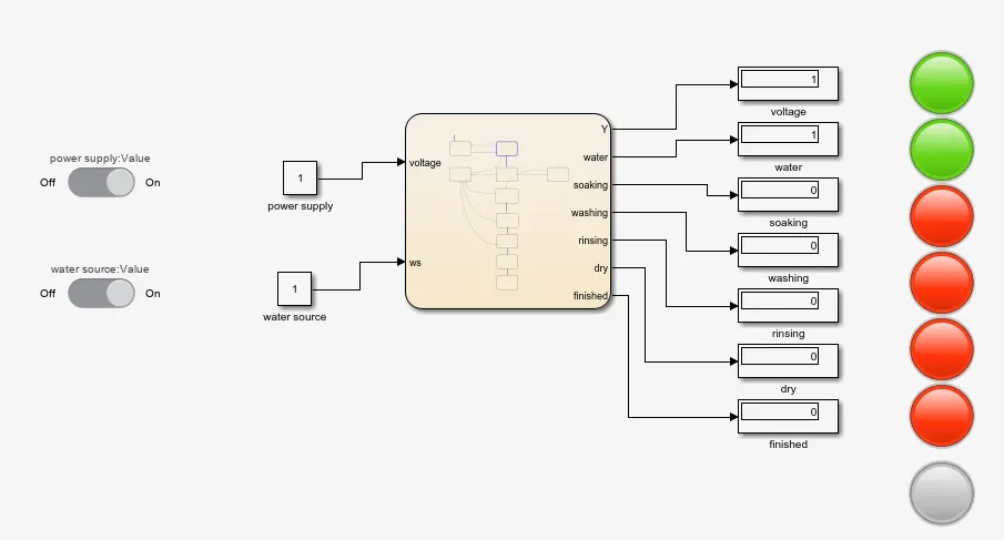
- While simulation is started the power is in ON state entire system is active.
- As well as the output voltage lamp and water lamp also in green colour as shown in model.
- Remain mode are soaking ,washing , rinsing and drying are in off state and showing red indication.
CONDITION 2: If the Water supply is not available, stop the process & indicate through LED
MODEL:
REPORT:
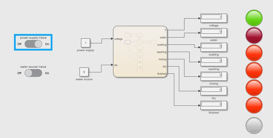
- In the condition if water is not available then entire process will stopped.
- As shown in model , while turning off the water source by using a slider switch block ,entire system are stopped ,and water lamp is indicating dark red colour light .
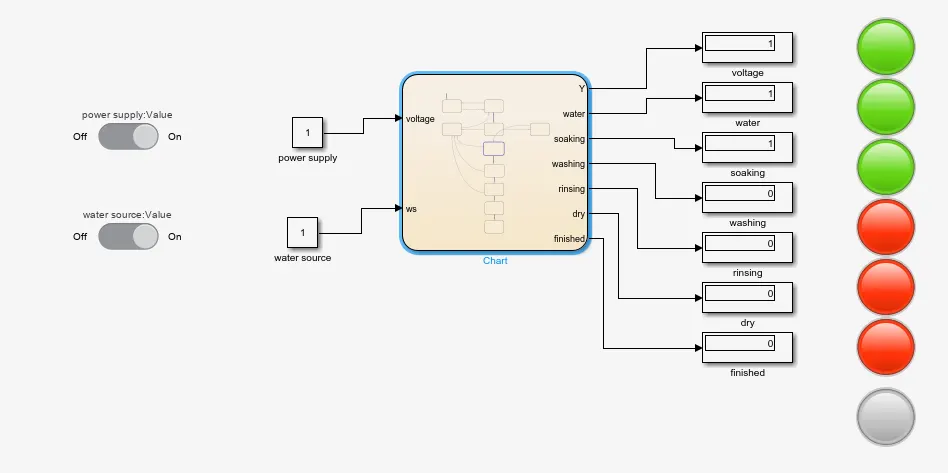
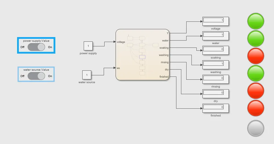
CONDITION 3 : Soaking time should be 200sec followed by washing time of 100sec
MODEL1:
MODEL2:
REPORT:
- In model1 system in soaking mode it will take 200 sec for soaking and soaking lamp is indicating the green light as shown in model 1 ,after that 200 sec .
- it will move to washing model as shown in model2 upto 100 sec its will be in washing mode and washing lamp is indicating green light as shown in model2.
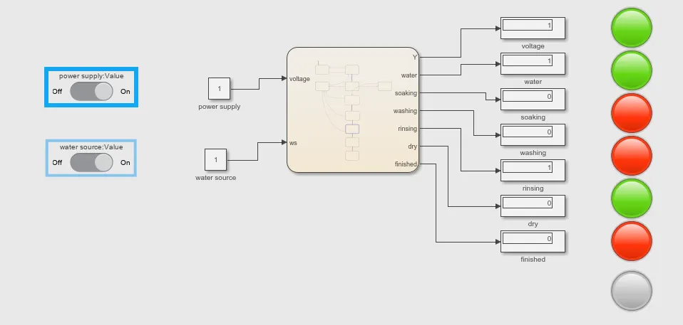
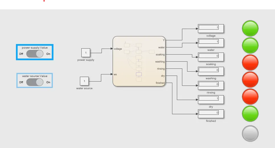
CONDITION 4: Rinsing happens for next 20 sec and dryer runs for 50 sec.
model1:
MODEL2:
REPORT:
- After washing mode , its will switch to rinsing mode for 20 sec and it will indicate green light on rinsing lamp in shown in model 1 .
- After rinsing ,it will switch to drying mode for 50 sec and it will show indication green light on drying lamp shown in model 2.
CONDITION 5 : After all process have completed turn on the finished led.
MODEL:
REPORT:
- If All the process is completed after the drying mode , Next step Finished light or lamp will be glow in to green colour as shown in model.
- This is the chart flow of washing machine .
RESULT: Control logic of a washing machine is implemented by using state flow with a sequence and Got the output.
2.Make a Simulink chart for the “Gear shift” logic as per below conditions:
Speed Range(kmph) Gear
0 to 15 1
16 to 25 2
26 to 40 3
41 to 60 4
Above 61 5
Give speed input while the simulation is running & display the gear number.
ANSWER:
AIM:To Make a Simulink chart for the Gear shift logic by giving speed input while simulation is running and display the gear number.
MODEL:
REPORT:
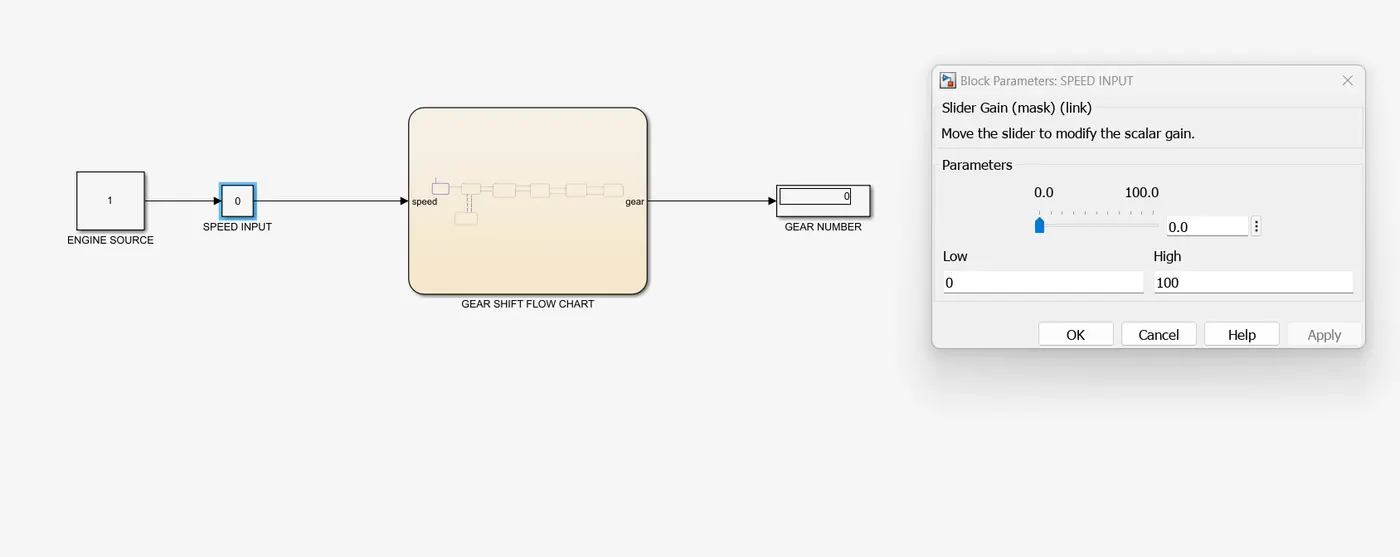
- In this model for gear shift , i have used chart for logic of gear shift.
- I have taken constant block for input value and its connected to slider gain block and named as a speed input.
- Which is connected to speed of the input to the chart as shown in model.
- Taken output as a gear numbers which is taken from the chart and its connected to display block named as a gear number.
FLOW CHART:
REPORT:
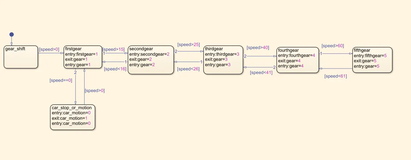
- As per the sequence data at the speed above zero ,the gear is shifted to first gear.
- if speed is above 15 km per hr then the gear of the car is shifted to second gear.if car speed is reduce to below 16km per hr then car gear will be shifts into first gear.
- if car speed is above 25km per hr then gear will be shifted into third gear .
- if car speed is above 61km per hr then car gear shift into fifth gear.
- if car is at idle then gear shift into zero or neutral position.
OUTPUT FIRST GEAR :
REPORT:
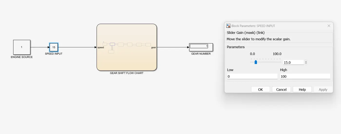
- When simulation is started ,the slider is moving from 0 to 15,the gear number is shifted from 0 to 1 position.
- Because given data is above 15 the gear number is shifted from 1 to 2 .
- If the speed input is 0 to 15 then the gear should be in first gear itself.
OUTPUT SECOND GEAR :
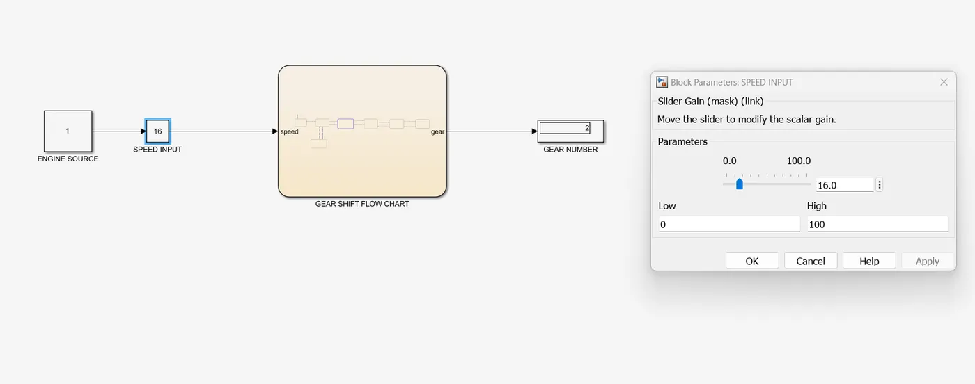
REPORT:
- When the slider is moved from 15 to 16 , the gear number is changed from first gear to second gear as shown in output model.
- If slider is move from 16 to 15 position then the gear number will be change from second gear to first gear.
- If the speed input is 16 to 25 then the gear should be in second gear itself.
OUTPUT THIRD GEAR:
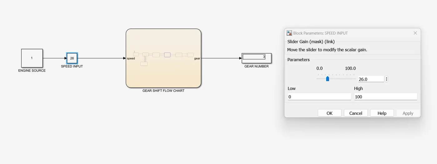
REPORT:
- When slider is moved from 16 to 26 ,the gear number is shifted from second gear to third gear.
- if value or speed input is 25 then gear number will be changed from third to second gear.
- If the input speed is between 26 to 40 then gear should be in third gear itself.
OUTPUT FOURTH GEAR:
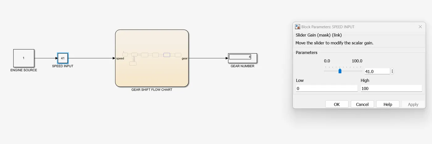
REPORT:
- When slider is moved above 40 then the gear number will be changed from third gear to fourth gear.
- if the input speed is in between 41 to 60 then the gear should be in fourth gear it self.
OUTPUT FIFTH GEAR :
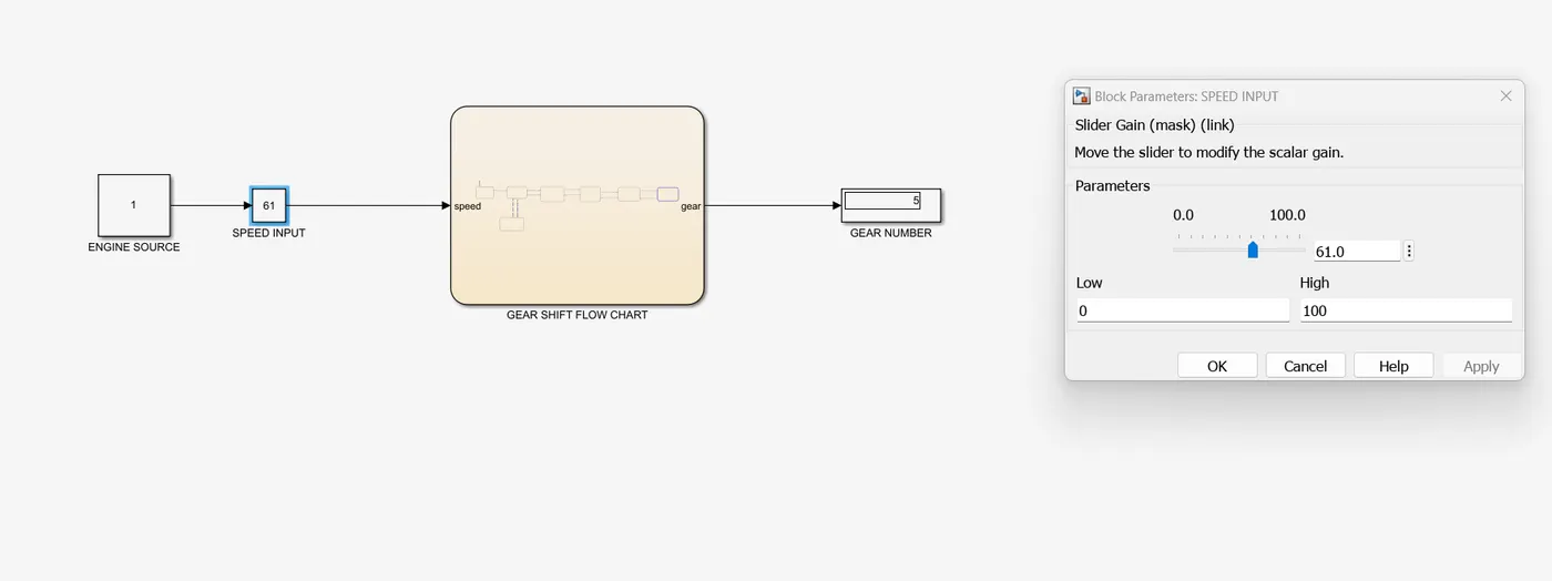
REPORT:
- If the slider is moved above 60 then the gear number is changed from fourth gear to fifth gear as shown in output model.
- if speed input is above 61 then the gear should be in fifth gear itself.
RESULT:The simulink chart for Gear shift logic is constructed with Given conditions and Got the output of gear numbers.