Project 2 Adaptive Cruise Control
ANSWER:
AIM: To Develop The Simulink Model of Adaptive Cruise Control As per Requirements And To Create a Simulink Data Dictionary (SLDD) File.
SIMULINK MODEL:
REPORT:
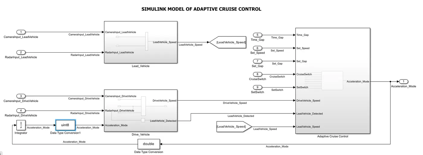
- In The Given Requirement of Lead_Vehicle sub-system have a two input signals.
- I have taken a Two inport blocks which given a signals names in requirement i.e, CameraInput_LeadVehicle and RadarInput_LeadVehicle as shown in above model.
- The Both signals are connected to a Lead_Vehicle sub-system as per requirement and taken output as a LeadVehicle_Speed. The output of LeadVehicle_speed is connected to a goto block which Transfer the data or signal from Goto block to From block which Invisble connections in simulink model.
- In The Given Requirement of Drive_Vehicle sub-system have a two input signals i.e, CameraInput_DriveVehicle, RadarInput_DriveVehicle and Another which taken as feedback signal from output signal of adaptive cruise control i.e, Acceleration_Mode.
- Acceleration_Mode is connected to datatype conversion which convert from uint8 to double because integrator support double datatype. Double datatype signal is connected to integrator block as shown in model.
- A integrator which helps to integrate an input signal with respect to time and provides the result as a output signal. After Getting signal from integrator is connected to data type conversion which convert datatype from double to uint8 which connected as input to the Drive_Vehicle sub-system.
- From the output signal of Drive_Vehicle sub-system are two output signals have taken out which connected to a input signal of Adaptive Cruise Control sub-system as shown in model.
- The output signal names of Drive_Vehicle sub-system i.e, DriveVehicle_Speed, LeadVehicle_Detected.
- LeadVehicle_Detected signal was created by taking a input signal of RadarInput_DriveVehicle is connected to signal conversion and output signal is connected to outport block named as LeadVehicle_Detected.
- LeadVehicle_Speed signal From block is connected to ACC sub-system, asper requirement Time_Gap, Set_Speed, Set_Gap,CruiseSwitch and SetSwitch signals are given as a input signals to the Adaptive Cruise Control sub-system as shown in model.
LEAD VEHICLE SUB-SYSTEM:
REPORT:
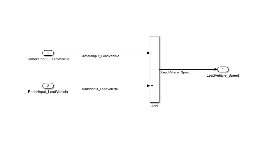
- In this sub-system as per Given Requirement, Two Input signal are CameraInput_LeadVehicle and RadarInput_LeadVehicle which both signals are connected to Add block as per requirement.
- CameraInput_LeadVehicle is use to display the road front view part to detect the clear objects on road path.
- The RadarInput_LeadVehicle is a radar sensor is usually at core of adaptive Cruise Control (ACC). Installed at the Front of the Vehicle. The system permanently Monitors the road ahead. As long as the Road ahead is Clear. Acc maintains the speed set by Driver.
- To Detect the LeadVehicle_Speed, Added the Both input signal of radar and camera Input signals. After adding both signal to add block as an output is taken as a Lead vehicle speed.
- This LeadVehicle_Speed is connected to a input signal of Adaptive Cruise Control sub-system.
DRIVE VEHICLE SUB-SYSTEM:
REPORT:
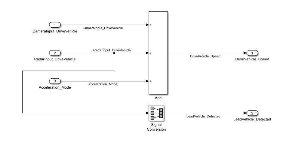
- In this sub-system have a three input signal as per requirement. i.e, CameraInput_DriveVehicle, RadarInput_DriveVehicle and Acceleration_mode.
- Camera input and Radar input drive vehicle are main input signals of Drive vehicle sub-system. which are added with through a Add block as shown in model.
- A Acceleration_Mode is a output signal of main model, which taken as feedback and connected to a Add block as shown in model.
- From These three signal are adding with a add block, as an output signal creates the DriveVehicle_Speed signal of the vehicle.
- From By passing the signal from RadarInput_DriveVehicle signal is connected to signal conversion which convert a signal from one type to another type signal.
- Signal Conversion is a fundamental process to condition measurement signal or output signal from one device to another device for further processing.
- After getting a output signal from a signal conversion is directly connected to the LeadVehicle_Detected output port block.
- These Both output signal of DriveVehicle_Speed and LeadVehicle_Detected are directly connected to a sub-system of Adaptive Cruise Control as shown in main model.
ADAPTIVE CRUISE CONTROL SUB-SYSTEM:
REPORT:
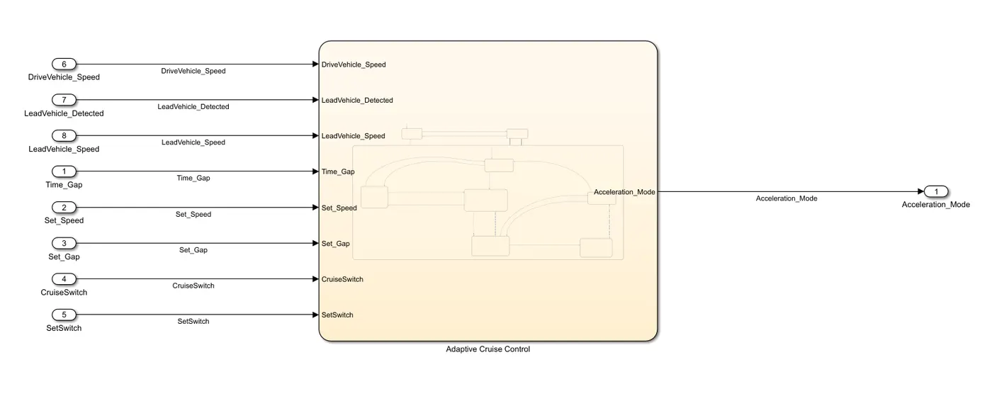
- As per requirement of Adaptive Cruise Control sub-system, All input signals are connected to the logical operation chart block which is using for logical opertator of a system.
- In this sub-system, I have taken a chart block for logical operation which are given as per requirement in adaptive cruise control.
- All signals are connected to their respective corresponding signals as shown in above model.
- The Signals are DriveVehicle_Speed, LeadVehicle_Detected, LeadVehicle_Speed, Time_gap, Set_Speed, Set_Gap, CruiseSwitch and SetSwitch which are connected to chart block and for output is Acceleration_Mode signal which is in Uint8 DataType as per conditions.
- DriveVehicle_Speed, LeadVehicle_Detected, LeadVehicle_Speed, Time_gap, Set_Speed, Set_Gap these signals are in Uint8 DataType and Minimum value is 0 and maximum value is 255.
- For CruiseSwitch and SetSwitch have a Boolean DataType as per condition and minimum value is 0 and maximum value is 1.
ADAPTIVE CRUISE CONTROL CHART:
REPORT:
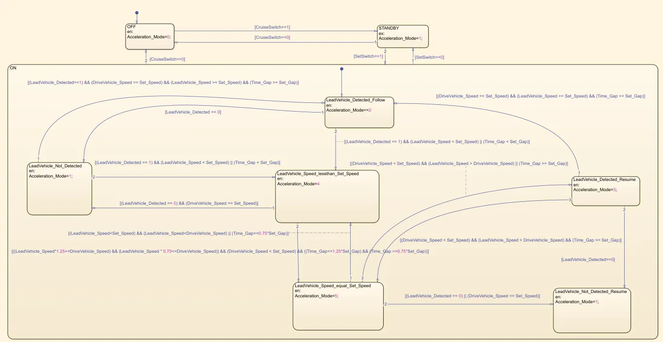
- As per requirement of this model Given a logical Operators, There are three type of modes which is OFF Mode, STANDBY Mode and ON Mode state logics.
- OFF Mode is mainly works has OFF state condition, When Acceleration_Mode is becomes 0 then OFF Mode state logic will be ON or Active state.
- If Given Condition of OFF mode State logic, When CruiseSwitch=0 Then OFF Mode state logic will becomes Active state or On state.
- If CruiseSwitch=1 then The logic signal will shift to another state logic i.e, STANDBY state logic.After shifting the STANDBY Mode, Its Becomes Active state or ON State and Acceleration_Mode will be 1.
- As per Given condition of STANDBY Mode, if SetSwitch=0 then STANDBY Mode gets or Become ON state or Active state.
- If SetSwitch=1 then signal will Shifts into ON state Logic, its becomes active or ON state.
- LeadVehicle_Detected_Follow state is On Mode, if condition is LeadVehicle_Detected=1 and Lead vehicle speed is less than set speed and Time gap is less than set gap then signal will shift into LeadVehicle_Speed_Lessthan_setspeed block or state. It will be On state.
- LeadVehicle_Detected_Follow condition that LeadVehicle_Detected =0 then the signal will shift into LeadVehicle_Not_Detected block or state. it will be On or active state.
- if LeadVehicle_Speed_Lessthan_setspeed condition that LeadVehicle_Detected =0 and Drivevhehicle speed = set speed then signal shift to Lead Vehicle Not detected block or state. it will On or active state.
- LeadVehicle_Not_Detected block condition that LeadVehicle_Detected =1 and LeadVhehicle_speed<Set_speed and Time_gap<Set_Gap then signal will shift into LeadVehicle_Speed_Lessthan_setspeed state block.
- If condition state to LeadVehicle_Not_Detected block that LeadVehicle_Detected=1 and Drivevehicle_speed==Set_speed and LeadVehicle_speed>=Set_speed and Time_Gap >= Set_Gap then signal will shift from LeadVehicle_Not_Detected to LeadVehicle_Detected_Follow .
- if condition of LeadVehicle_speed_equal_set_speed satisfied then the signal will be shift into LeadVehicle_speed_equal _set_speed block or logic state. its will be active mode. if the condition is not satisfied then its will back to previous logic state block.
- If lead vehicle detected =0 and Drive vehicle speed <=set speed then its will shifted to lead vehicle not detected resume logic block or else if condition is satisfied then it will shift to Leadvehicle_Detected_Resume block or logic state. its will active mode.
- if Leadvehicle_Detected_Resume condition is not satisfied then it will shifted to LeadVehicle_speed_equal _set_speed .
- if leadvehicle_Detected =0 in Leadvehicle_Detected_Resume then its will shift to LeadVehicle_Not_Detected_Resume is Active state or On state.
- In LeadVehicle_Detected_Resume condition that drive vehicle = set speed and lead vehicle >= set speed and Time Gap >= set gap then signal will move to LeadVehicle_Detected_Follow . it will becomes On state or active state.
SLDD FILE:
REPORT:
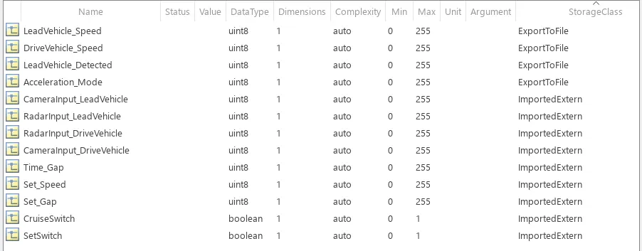
- Creating a Simulink Data Dictionary file, as per Given Requirements that All signals of input signal must be in Imported Extern StorageClass And OutPut Signal Of a system must be in ExportToFile StorageClass. Storage class For local signal are Localizable and Storage class for Calibration signals are Const.
- As per Requirement that, All Dimensions must be change from -1 to 1. I have Changed All Signals Dimensions into 1 as shown in SLDD File.
- For Input signals are LeadVehicle_Speed, DriveVehicle_Speed, LeadVehicle_Detected, Acceleration_Mode, CameraInput_LeadVehicle, RadarInput_LeadVehicle, CameraInput_DriveVehicle, RadarInput_DriveVehicle, Time_Gap, Set_Speed, Set_Gap. These All signals DataType is in Uint8 as per Given Requirement. The Dimensions of all these signals are 1.
- These All signals have a Minimum value is 0 and Maximum value is 255 as per requirements.
- LeadVehicle_Speed, DriveVehicle_Speed, LeadVehicle_Detected, Acceleration_Mode are Output signals of a model. The storage class of these signals are in ExportToFile. Dimension are 1 and DataType are in Uint8.
- CameraInput_LeadVehicle, RadarInput_LeadVehicle, CameraInput_DriveVehicle, RadarInput_DriveVehicle, Time_Gap, Set_Speed, Set_Gap. These signals are a Input signals of the model As per requirements. These signals have a Dimensions are 1 and DataType is in Uint8, These signals have a minimum value is 0 and maximum value is 255. These signal storage class is in ImportedExtern.
- CruiseSwitch and SetSwitch are a Input signals, These Two signals have Boolean DataType as per requirement. Dimensions are 1. The Minimum value of these signals are 0 and Maximum values is 1. Storage class is ImportedExtern.
RESULT: The Simulink Model Of Adaptive Cruise Control is Developed and The Simulink Data Dictionary (SLDD) file is created as per given Requirements.