Project
QUESTION:Carry out a system-level simulation of an all-terrain vehicle and Prepare a technical report explaining the model properties & comments on the results.
ANSWER:
AIM OF THE PROJECT : To carry out a system-level simulation of an All Terrain vehicle & To run the simulation for analyze the output results and To prepare a technical report explaining the model properties & comments on the results.
OBJECTIVE: To run the simulation of given all-terrain vehicle model & Analyze the output results & prepare Technical report by explaining the model properties & comments on the results.
THEORY: It is a small open motor vehicle with one seat & three or more wheels fitted with a large tyres.Its designed for use on rough ground,ATV's are valuable tool.However, they are mainly used for recreation like racing and trail riding.All terrain vehicle is known as quad or four wheeler.It's made in united states.
The Baja all-terrain vehicle engine have a 305cc,10hp petrol engine.the baja cars steering system consists of a custom molded attached to a hollow steel tube, which drives an aluminium pinion and rack system in order to steer the car left and right.All-terrain vehicle is also known as Light utility vehicle.
USES: All-terrain vehicle are among the most useful land vehicles ever invented.Designed to combat the hazards of different kinds of terrain.it's uses for every works site areas & it's very easier to travelling for the drivers.
MODEL1:
BAJA ATV MODEL (WITH OUT LOOKUP TABLE):
CVT VEHICLE BODY
REPORT:
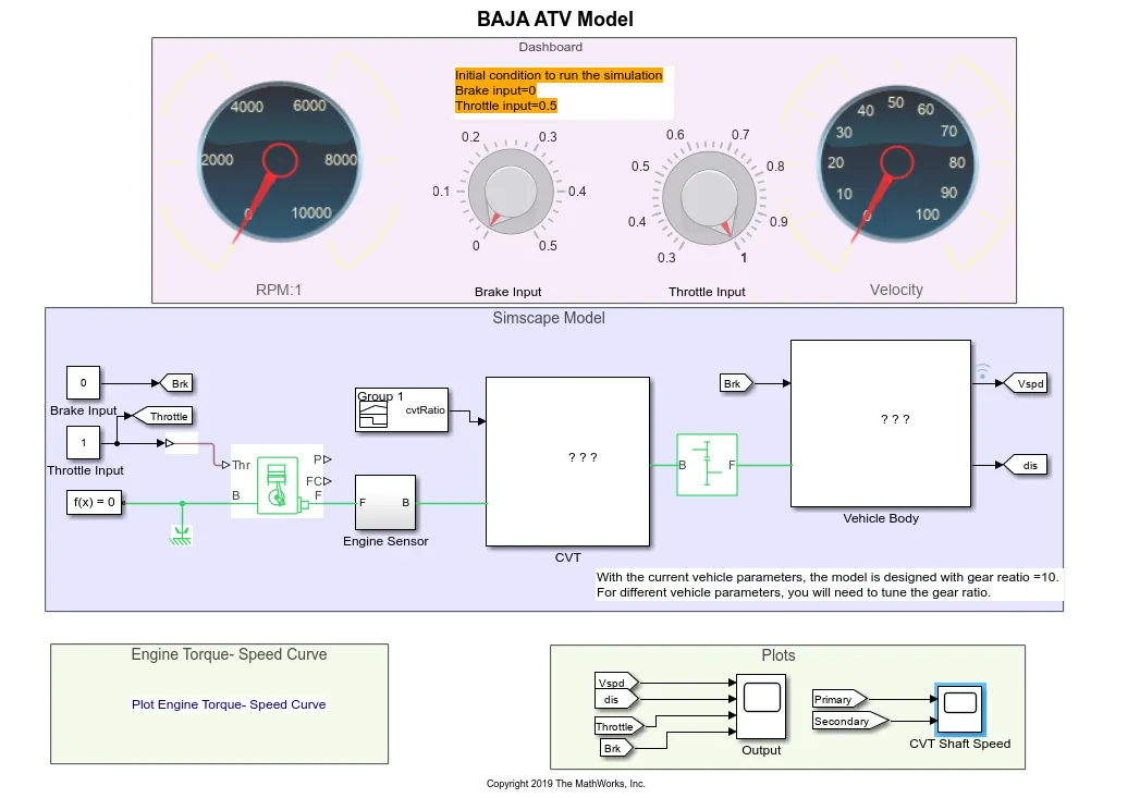
- In this model,for input source two constant block have taken,one is for brake input source and another one is throttle input source which is connected with goto block as shown in model.
- throttle input is given to generic engine block for accelarate the engine to run the maximun Rpm.
- From the 'B' point of generic engine is connected with a solver configuration,which is specifies the solver parameters that model needs before begin the simulation.Across the generic engine and solver configuration is connected a mechanical rotational reference block,which reference point or frame,for mechanical rotational ports.All rotational ports that are rigidly clamped to the frame must be connected to a mechanical rotational reference block.
- From the generic engine output source is connected with input of the engine sensor,which is used to sence the engine RPM(Revolutions per minute), and Across the 'F' point and 'B' point is parallely connected to a input source of a cvt sub system block as shown in model.
- The output of cvt sub-system block is connected to a input of simple gear block,which to adjust the gear ratio of the vehicle wheels.from the output of simple gear block is connected to input signal of vehicle body sub-system.from block ,brake input is given into the vehicle body which is connected with a double brake shoe block.
- For the output results taken a vehicle displacement , brake , throttle , cvt shaft speed of primary and secondary rpm by using a variable gear ratio block. By using a scope block , we can easily identify the output results of the vehicle.
- To varying the input source of a vehicle taken a two knob block which is connected to a brake and throttle block as shown in model. and as well as , taken a two circular guage block to check the present vehicle RPM and present speed or velocity of a vehicle.
SUB-SYSTEM OF ENGINE SENSOR :
REPORT:
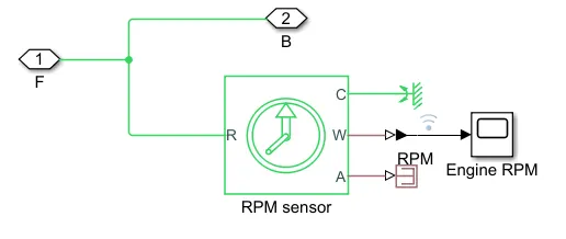
- From the engine source is connected with a RPM sensor which is used to sense the speed of the engine shaft by using sensor's.
- By using it, we can figure it out actual RPM of the engine which gives the output source from the engine shaft.
- To check the RPM output result to connect with a scope block which is use to get actual RPM value.,but scope block is a simulink signal parameter block which doesn't support the mechanical signal.
- By using a ps-simulink converter block which helps to convert signal from mechanical or physical signal to simulink signal.now we can easily connect with scope block from converter block.
SUB-SYSTEM OF CVT :
 REPORT:
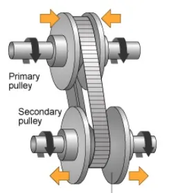
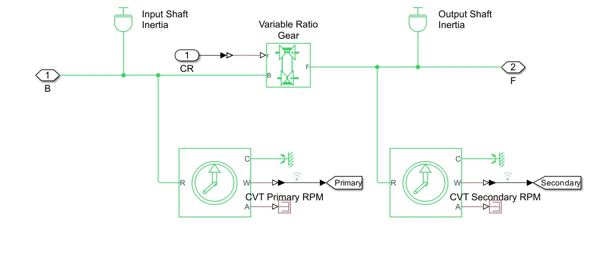
- There is a two shaft inertia, one is input inertia and another is output inertia.In between these two inertia had connected to a variable ratio gear ,because dynamically transfers the motion and torque.To improve the gear ratio of secondary cvt RPM compare to primary one.
- For the input source of cvt ,as arranged a signal builder block ,it is a simulink signal to convert it by using simulink-ps converter to convert into physical signal.Because the variable ratio gear is a mechanical simulation block.
- Primary cvt RPM which connects the direct input source of the cvt output results & secondary cvt RPM which connects from the output of the variable ratio gear block,to get the better high ratio output results.
SUB-SYSTEM OF VEHICLE BODY:
REPORT:
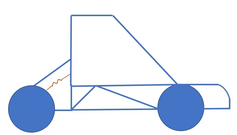
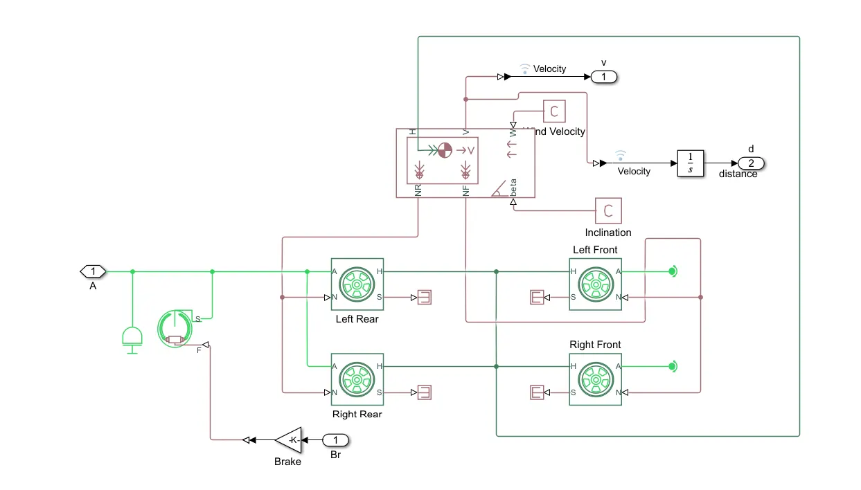
- In this model , the vehicle body block is consider for both velocity and displacement output,which is connected through ps-constant block as shown in model,which consider as a wind velocity and inclination for the vehicle body as an input source.
- From the 'V' point of vehicle body block is interconnected with both velocity and displacement.,but both velocity and displacement have a ps signal .To convert the signal by using a ps-simulink converter .
- After converting the signal ,displacement signal is connected with integrator block ., Because of displacement is inversly proportional to the velocity or speed of the vehicle and its connected through Goto block ,a block which passes its input to its corresponding from block.
- For wheel of a vehicle taken a tyre(magic formula ) blocks., All 'H' points of the tyres are commonly connected with to the velocity body block in the 'H' point as shown in model and induvidual tyres block are connected with a induvidual ps-terminator block. A ps-terminator block is for unconnected physical signal output.
- For the front wheel tyre blocks only have a rotational free end. rotational free end block is mechanical rotational port which rotate freely without torque , that block is connected into 'A' point for front wheels only.
- For rear wheel tyres have a commonly connected in 'A' point ,which is use for double shoe brake rear braking system to apply a brake for the vehicle.
- From the brakeblock is connected a gain block which use for multiplies the input by a constant value.After that signal from the brake block is in simulink to convert it into physical signal by using simulink-ps converter.now easily connect with a input brake signal to the double shoe brake block ,now vehicle brake system is ready.
OUTPUT:
PLOT1: VEHICLE OUTPUT
REPORT:
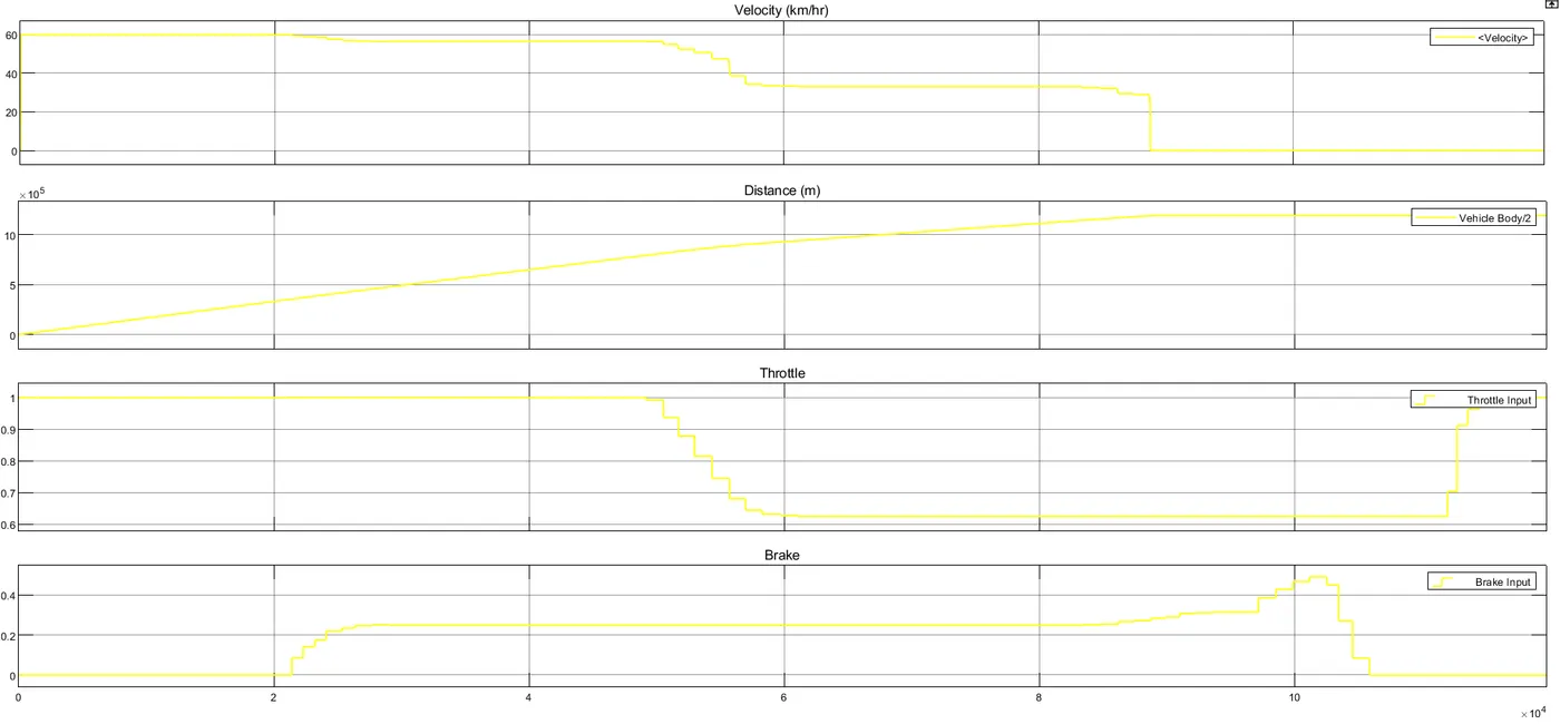
- When simulation is started running, vehicle velocity and displacement are started increasing.The throttle of vehicle are set to be in 1 position and brake of vehicle is 0 position.
- While applying the brake of the vehicle,as a result output, we have abserved that brake level are increasing from 0 to 0.1,0.2,...so on.,the speed or velocity of vehicle is slightly decreasing ,as well as displacement or distance also decreases.
- after applying brakes , the velocity of vehicle is reduces from 60 to 55 kms/hr, more over losses also occurs with 5 km/hr speed losses in the vehicle, and also distance also decreases.
- I have observed that , when throttle is set from 1 to 0.65 as an input for the vehicle ., after applying brakes from 0.2 to 0.3 , suddenly vehicle has stopped and engine is getting off there itself.velocity or speed of vehicle is becomes 0 zero position and distance also in constant . as noticed on the output plot of the vehicle result.
PLOT2:PRIMARY AND SECONDARY CVT SHAFT OUTPUT:
REPORT:
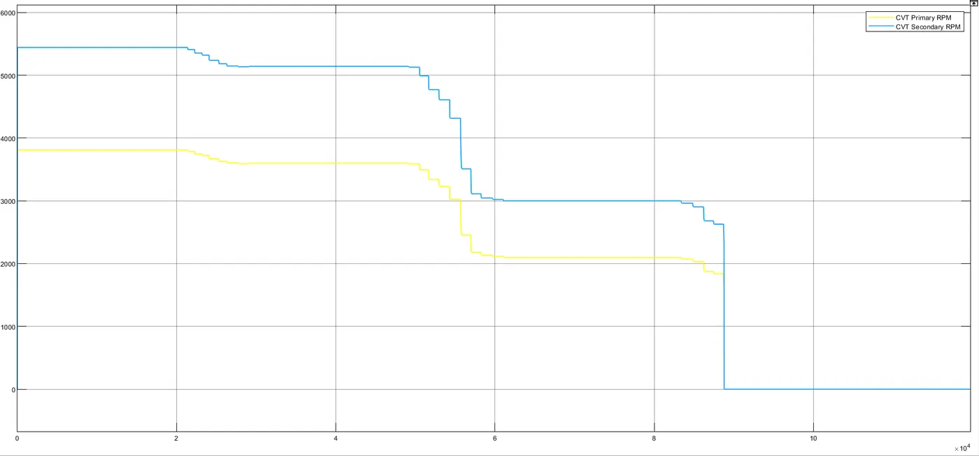
- By using a variable ratio gear blolck in between the primary cvt RPM and secondary cvt RPM.we have observed that both rpm have a difference output rpm with difference of 1700 RPM.
- When simulation is running, both rpm are moving together with same time interval .But both output values are different as shown in plot output.
- In this plot observed that secondary cvt RPM have more rpm losses compare to primary cvt RPM.while applying brakes of an vehicle , secondary cvt rpm have more losses and quickly reducing rpm output result as shown in output plot.but primary cvt have less losses after applying brakes.
- At the point of time interval, after applying a brake of a vehicle, the vehicle velocityis decreasing and distance of an vehicle is becoming constant .
- At the time of a vehicle both primary and secondary cvt rpm's are joint together at time is 8.9sec and slightly decreases from 1900 rpm to 0 rpm.
CURVE PLOT:
REPORT:
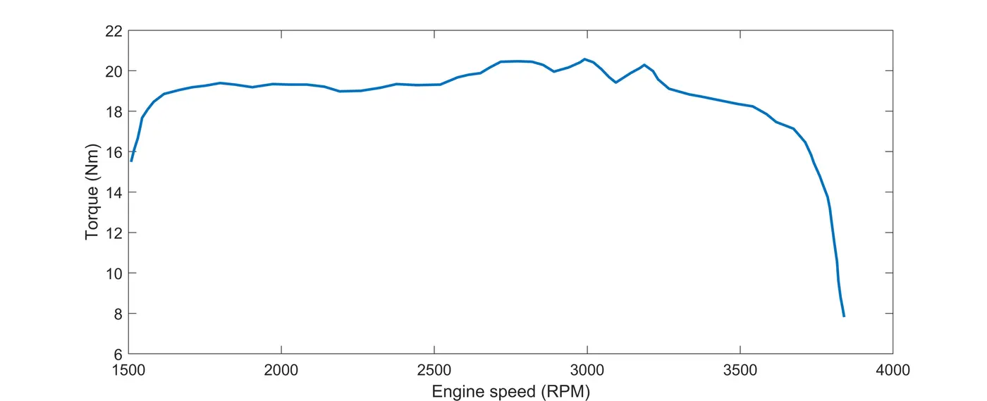
- In intial state of a torque value increases from 15.9 to 21 nm with 1500rpm to 3000rpm .by observing the curve that in starting point vehicle torque more then speed.
- after the 3000rpm gear ratio is changed for higher gear to speed up the vehicle.when engine rpm is reached to higher rpm level , the level of torque is reduced from 19 to 8 in between the 3250 rpm to 3800 rpm .
MODEL2:
BAJA ATV MODEL (WITH LOOKUP TABLE):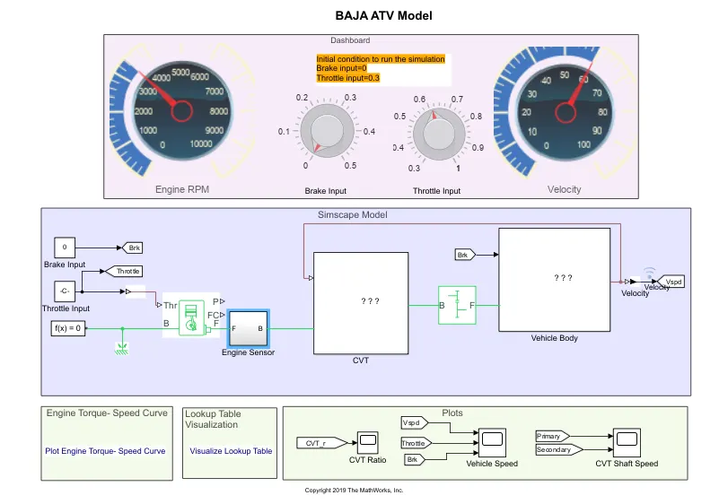
CVT VEHICLE BODY
REPORT:
- In this model is with lookup table,a lookup table is an array of a data that maps input values to output values, there by approximating a mathematical function. Given a set of input values, a lookup operation retrieves the corresponding output values from the table.
- in this model, we are using a 1-D lookup table,which generates an output signal by interpolating based on a given dataset and input value. the purpose of a lookup table is used to transform the input data into a more desirable output format.
- In this model, to run the simulation, first we have to run the lookup table in a dataset,for input data of cvt ratio.by using a simulink creating a 1-D code to implement the input data to the model.
- We have connected the output signal vehicle body to input of cvt sub-system as shown in model.from it connected to a 1-D ps-lookup table block.
- From this lookup table model, we have taken a separate cvt ratio, because of lookup table data already implemented as an inoput to that ps-lookup table block.
- Remaining parameters of vehicle have taken commonly as a previous model of without ,lookup table model.
SUB-SYSTEM OF CVT:
REPORT:
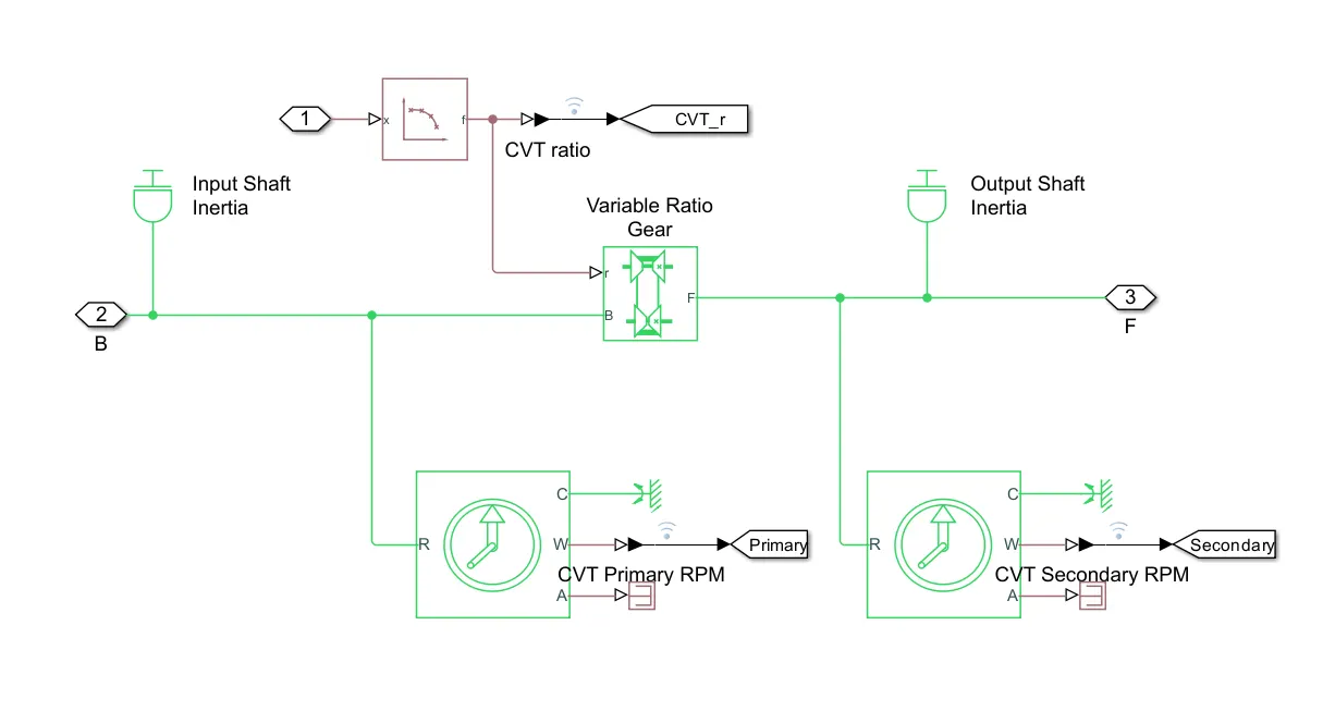
- In this sub-system of cvt, have a ps-lookup table block,which given input data from the lookup visualization code and entered the input data in dataset format.
- we have placed a ps-lookup table block in sub-system of cvt and given a input source to the variable ratio gear block.its connected to 'R' point as shown in sub-system of cvt model.
- Now, we have using a ps-simulink converter to convert the signal from physical signal which coming from ps-lookup block to simulink signal. after converting it and to connect with goto block which named as a cvt_r.
SUB-SYSTEM OF VEHICLE:
REPORT:
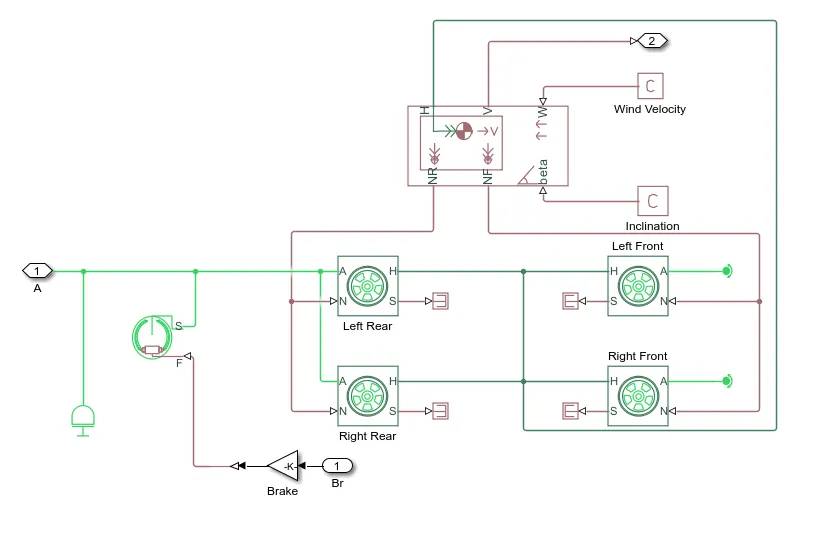
- In this sub-system, there is no converter blocks , because of we didn't taken a output velocity of vehicle like previous model.
- From the 'V' point a vehicle body block tooked a signal which in ps signal and directly connected to goto block.
- remaining block are doesn't changed any thing same as a previous model of sub-system vehicle in without lookup model.
OUTPUT:
PLOT1:OUTPUT OF CVT RATIO:
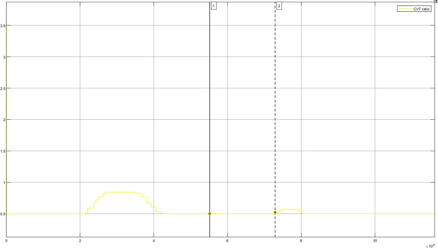
REPORT:
- Observing the output result of cvt ratio, at starting stage when simulation started running, the value of cvt ration further decreases from 3.5 to 0.5.
- when throttle is decreases and brake value is increases at that time interval cvt ratio slightly increases from 0.5 to 0.8.
- when second point reaches in cvt ratio trying hard to rise the maximum output from cvt ratio in a time interval between of 7.5 to 8.
PLOT2: OUTPUT OF VEHICLE SPEED:
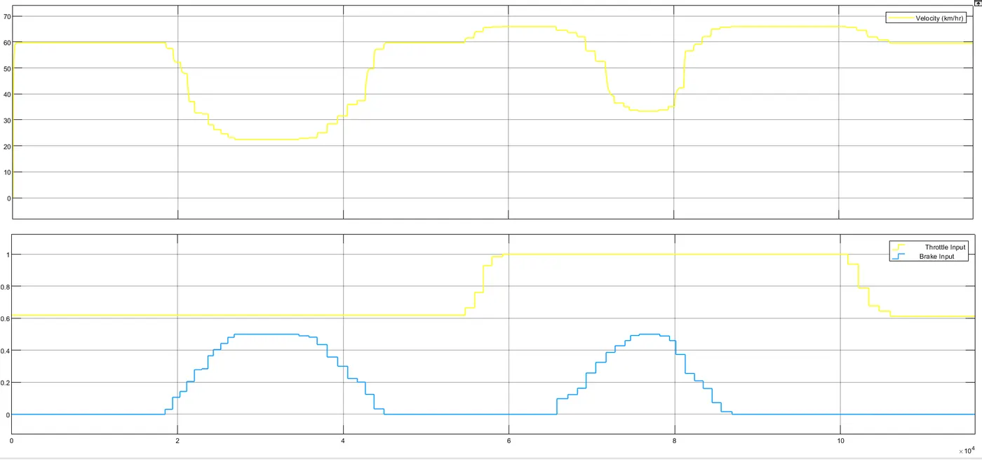
REPORT:
- When simulation started running , the throttle input is 0.6 and brake iput is at 0 . due to input throttle source vehicle started moving with a speed or velocity. intially at starting point vehicle is in rest or idle .
- The vehicle started with a minimum time to reach maximum speed or velocity . after reaching maximum speed applied a brake slowly from 0 to 0.5.
- when brake is applied , speed or velocity of vehicle is going decresing from maximum to minimum speed.After leaving the brake again the vehicle speed or velocity started rising up to run top speed . By increasing a throttle value with help of knob block , the vehicle speed further increases and maximum top speed of vehicle is near to 70 km/hr.
- when throttle input is 1 with out applying a brake ,the vehicle top speed upto 66-68 km/hr as shown in output plot.
- in this lookup table model of all-terrain vehicle ,there is no sudden off condition of the vehicle engine as compare to with out look up table model after reaching a brake value of 0.3.
- its continues the engine in running condition without any off mode.
PLOT3:OUTPUT OF CVT SHAFT SPEED:
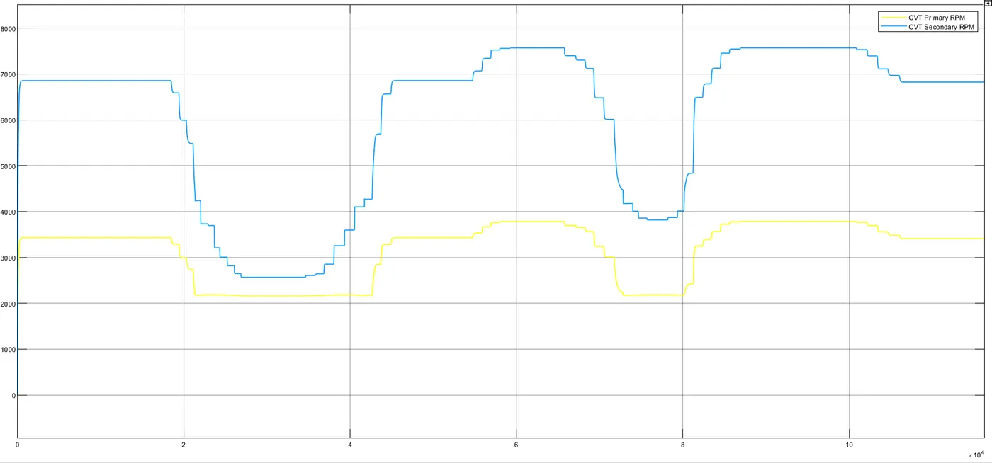
REPORT:
- At initial point of starting stage the rpm of both primary and secondary cvt rpm reaches to maximum output rpm.primary rpm reaches to 3500 rpm and secondary cvt rpm reaches to 6900 rpm.
- when brake is applied in a time interval of 2 to 4sec .the both cvt rpm are decreases from maximum rpm to minimum rpm as shown in output plot.
- After leaving brake and increasing the throttle value of vehicle by using knob block, both primary and secondary rpm further increases to reach maximum rpm.
- After getting the output results of cvt shaft speed , i have observed that secondary cvt rpm have a more rpm losses compare to primary cvt rpm.almost secondary cvt rpm is reaching an equal level of rpm of an primary cvt rpm in time interval of 2 to 4 sec.
- Increasing the throttle input of vehicle , the secondary cvt rpm further increases to reach maximum rpm compare primary cvt rpm in between time interval of 4 to 7 sec.
RESULT:
The system-level simulation of given all-terrain vehicle is sucessfully carried out and prepared a technical report by explaining the model properties, analyzed and commented on the output result.