Project 1 (Mini Project on Vehicle Direction Detection
ANSWER:
AIM: To Develop The Simulink Model Of Vehicle Direction Detection As Per Requirement. To Create a Simulink Data Dictionary (SLDD)File.
SIMULINK MODEL:
REPORT:
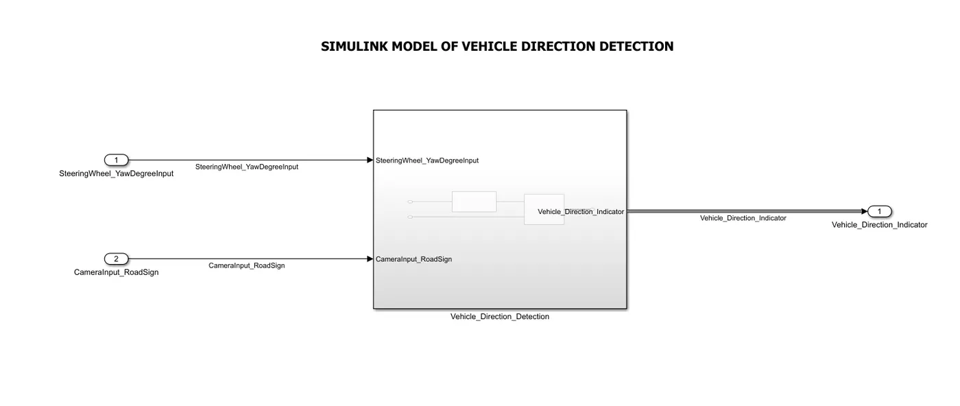
- In this simulink model of vehicle direction detection, The input signal have taken as steeringwheel_YawDegreeInput which is use to know the angle of steering wheel.
- Another signal have taken the cameraInput_RoadSign which is use to Detect the Road sign on the road Direction.
- The Both signal have taken and connected to the Vehicle_Direction_Detection sub-system as shown in simulink model.
- As per given requirement of Input signals of the model is that for steeringwheel_YawDegreeInput is a input signal and DataType is must be in int16.Min and max values are given to the input signal, the units is in Degree.
- For the CameraInput_RoadSign signal also have a Data type which is given as Boolean type,The min value is 0 and maximum value is 1.
- The Vehicle_Direction_Indicator signal is taken as output signal of the Vehicle direction detection simulink model.
- Which output signal of Vehicle_Direction_Indicator is in Boolean Data type and Minimum value is 0 and Maximum is 1 which taken as output signal of a model.
VEHICLE_DIRECTION_DETECTION SUB-SYSTEM:
REPORT:
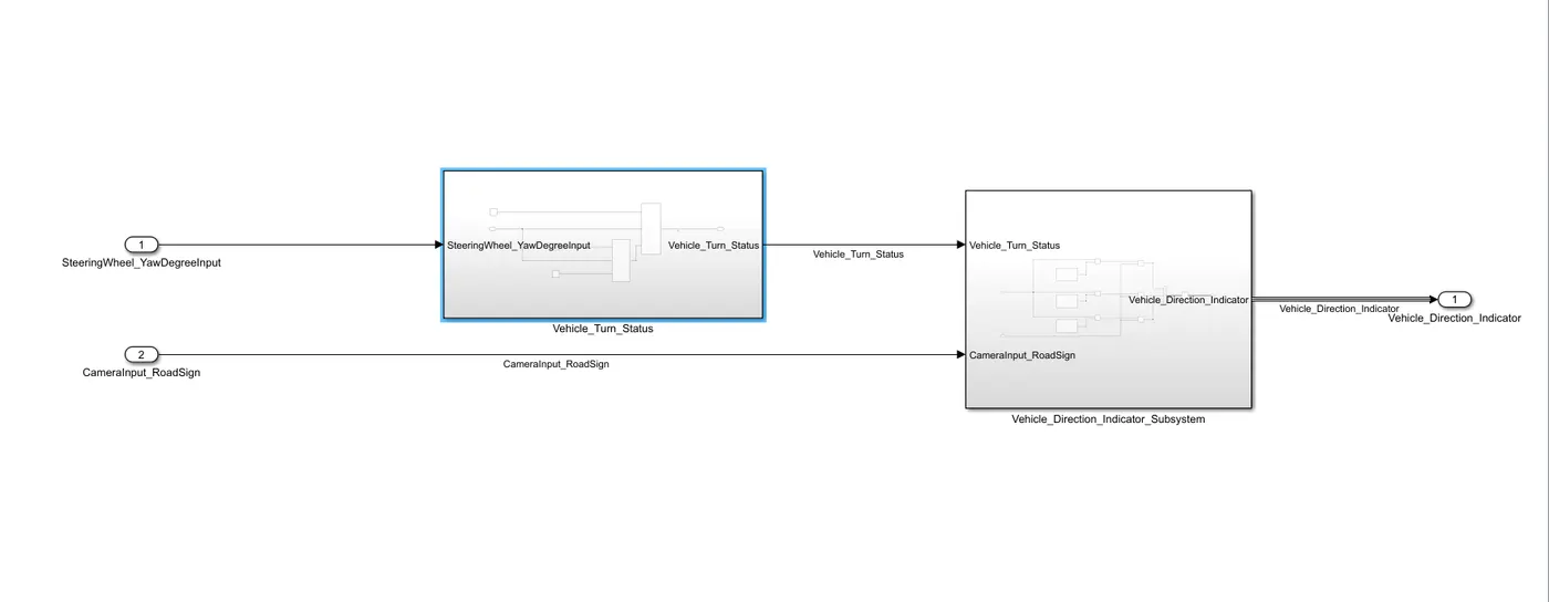
- From the Input signals of SteeringWheel_YawDegreeInput inport signal which is connected to a input signal of Vehicle_Turn_Status sub-system as shown in model and CameraInput_RoadSign Inport signal which is connected to Input signal of Vehicle_Direction_Indicator_Subsystem as shown in model.
- From The output signal of Vehicle_Turn_status sub-system which is connected to a input signal of Vehicle_Direction_Indicator_Subsystem as shown in model.
- The Output signal of this model as taken i.e, Vehicle_Direction_Indicator which is connected to a outport block as shown in model.
- In the output port block have a three output signals i.e, Right_turn, Left_turn, Straight_Drive signals.
- As per Given Requirement that for Vehicle_Turn_Status subsystem is consider as a Local Signal and DataType of a subsystem is int16.The minimum value is -180 and maximum value is 180, The Units is in Degree.
VEHICLE_TURN_STATUS SUB-SYSTEM:
REPORT:
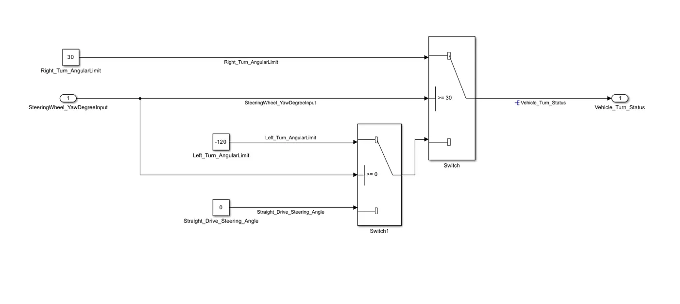
- From the input signal of SteeringWheel_YawDegreeInput is commonly connected to a both switch blocks as show in model of Vehivle_Turn_Status sub system.
- The Right_Turn_AngularLimit values is 30 which is consider in a constant block and connected to a primary connectivity of a switch block
- For switch block threshold is set as a >=30, The input signal is greater than or equal to Right Turn angle limit then the switch will be in ON state.
- When input value is 0 then the switch1 block wiil be ON state and switch block will be off state.The Straight_Drive_Steering_Angle value is 0.
- The switch1 block give a value output as a Left turn angle limit that is -120 as a output which is connected to a secondary input of switch block as shown in model.
- When the input value is -120 then left turn angle limit is reached and its indicate to come back initial position i.e, straight_Drive angle. the value is 0.
- From the switch block output has taken a input signal of Vehicle_Direction_Indicator has input signal. Which is connected to a Outport block of vehicle_Turn_Status named block.
VEHICLE_DIRECTION_INDICATOR SUB-SYSTEM:
REPORT:
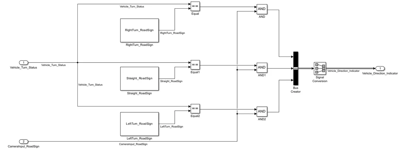
- In this subsystem of Vehicle_Direction_Indicator, The Input signal of Vehicle_Turn_Status is commonly connected to a equal ,equal1 and equal2 blocks as shown in model.
- In simulink Data Dictionary file have given a RightTurn_RoadSign value as 30, straight_RoadSign value is 0 and LeftTurn_RoadSign value is -120.
- These Three RoadSign values constant blocks has connected to a individual Equal blocks as shown in model.
- The equal block works that both input signal must be same then equal block gives a output signal as 1 value.
- From output signal of equal blocks is connected to a AND block as a primary port as shown in model, From the Input signal of CameraInput_RoadSign siganl is commonly connectd to a individual AND blocks with different RoadSign values as shown in model.
- AND block works when value input is x=0 and y=0 then output is 0. If x=0 and y=1 then the output is 0.
- if x=1 and y=0 then output is 0, if x=1 and y=1 then output value of AND is 1.These Three AND values are connected to a BUS creator block.
- From the bus creator output values are connected to a signal conversion block as shown in model.
- The output value of Signal conversion is connected to a outport block of Vehicle_Direction_Indicator block which is taken as a output value of Vehicle Direction Detection simulink model.
SIMULINK DATA DICTIONARY:
REPORT:
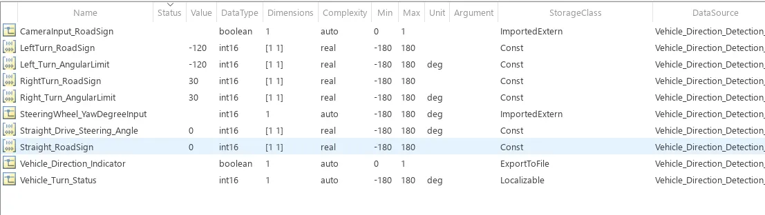
- The simulink data dictionary file has been created as per given Requirement of given signals values and parameters values.
- For Input signals of SteeringWheel_YawDegreeInput values are Inputsignal, Datatype is int16, Dimension is 1, minimum value is -180 and maximum value is 180 and Units is Degree.The storage class is Importedextern.
- Another input signal of CameraInput_RoadSign value is Inputsignal, DataType is Boolean, Dimension is 1, Min value is 0 and maximum value is 1 and storage class is Importedextern.
- Vehicle_Turn_Stauts value is given as a local value of a model, i.e, DataType is int16, dimension is 1, minimum value is -180 and maximum value is 180. Unit is Degree and storage class is localizable.
- LeftTurn_AngularLimit, RightTurn_AngularLimit and Straight_Drive_Steering_Angle is a calibration type signals in the system, These three signals have a int16 DataTypes, Dimension is [1 1],
- These three signals minimum value is -180 and maximim value is 180, LeftTurn_AngularLimit initial value is -120, RightTurn_AngularLimit initial value is 30 and Straight_Drive_Steering_Angle initial value is 0. These three signals have a unit is Degree. Given these Three signal storage class has a const as per given requirements.
- Straight_RoadSign, RightTurn_RoadSign and LeftTurn_RoadSign is a calibration signal type.These three signals have a int16 DataType, the Dimension is [1 1], minimum value is -180 and maximum value is 180.Straight_RoadSign initial value is 0, RightTurn_RoadSigninitial value is 30 and LeftTurn_RoadSign initial value is -120.Consider these three signals storage class as const.
- The Vehicle_Direction_Indicator is a Output signal Type, DataType is Boolean, Dimension is 1, minimum value is 0 and maximum value is 1. consider storage class as ExportToFile.
OUTPUT:
TEST CASE TEMPLATE:
REPORT:
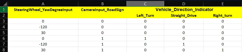
- When steeringwheel_YawDegreeInput is 0 and CameraInput_roadsign is 0 then all left_Turn, right_turn and straight_Drive values is 0.
- When steeringwheel_YawDegreeInput is -120 and CameraInput_roadsign is 0 then all left_Turn, right_turn and straight_Drive values is 0.
- When steeringwheel_YawDegreeInput is 30 and CameraInput_roadsign is 0 then all left_Turn, right_turn and straight_Drive values is 0.
- When steeringwheel_YawDegreeInput is 0 and CameraInput_roadsign is 1 then left_Turn value is 1, right_turn value is 0 and straight_Drive value is 0.
- When steeringwheel_YawDegreeInput is -120 and CameraInput_roadsign is 1 then left_Turn value is 0, right_turn value is 0 and straight_Drive value is 1.
- When steeringwheel_YawDegreeInput is 30 and CameraInput_roadsign is 1 then left_Turn value is 0, right_turn value is 1 and straight_Drive value is 0.
RESULT: The Simulink Model of Vehicle Direction Detection is Developed as per Requirement. Simulink Data Dictionary is created.