Week - 4
Answers
Q-1
Objective
- Implement control logic of washing machine using stateflow.
Explaination
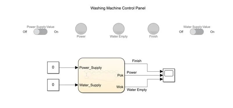
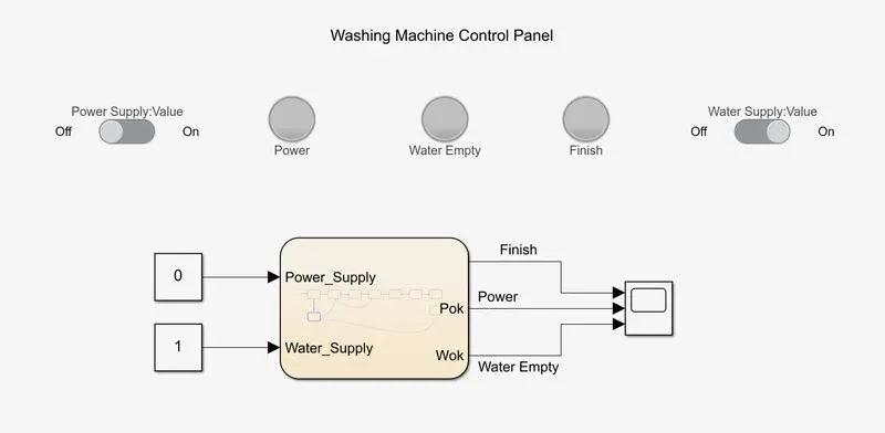
- In the showing in fig washing machine control panel and control block is shown.
- In the Control panel Power Supply Switch and Water Supply Switch is shown.
- Power, Water Empty and Finish Indicator are also shown in control panel.
Working
- After knowing all the components we start the simulation in infinite time mode.
- After start simulation we turn on the 'Power Supply Switch'.
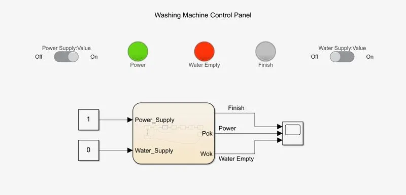
- After turn on power switch 'Power Indicator' and 'Water Empty Indicator' is turn on.
- In this case we only turn on the power supply water supply is remain off position so water Empty Indicator is on.
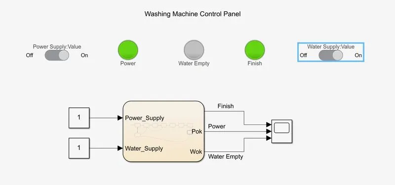
- After this process is complet we turn on the 'Water Supply Switch'.
- After turn on 'Water Supply Switch' water empty indicator is off and washing machine model is able to go next step.
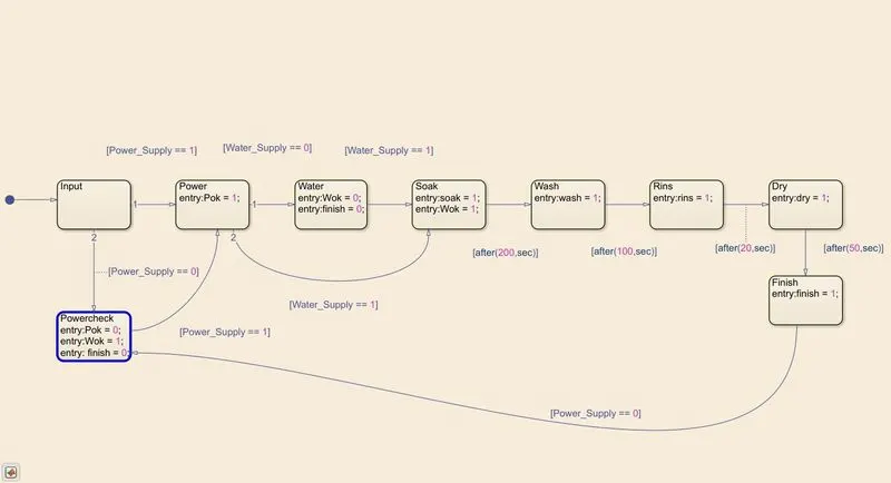
- As shown in fig after water supply available soaking process is start.
- This process is continue for 200 seconds.
- After completing soaking process we move to washing process.
- Washing Process is continue for 100 seconds.
- After completing washing process Rinsing process is start.
- Rinsing process is continue for 20 seconds.
- After Rinsing process Drying process is start.
- Drying Process is continue for 50 seconds.
- After completing all of this process process cycle is stop and 'Finish Indicator' is turn on.
- We can restart cycle by turn off and again turn on power supply.
Results
- After making this washing machine model we learn about basics of how to washing machine is work and what kind of process is completed in fully automatic washing machine.
- We also understand proper way to make stateflow chart.
Simulink file of this Model is atteched to hear, it can be open by clicking this link "Simulink File for Washing Machine Model"
Q-2
Objective
- Make a Simulink Chart of Gear Logic using Stateflow.
Explaination
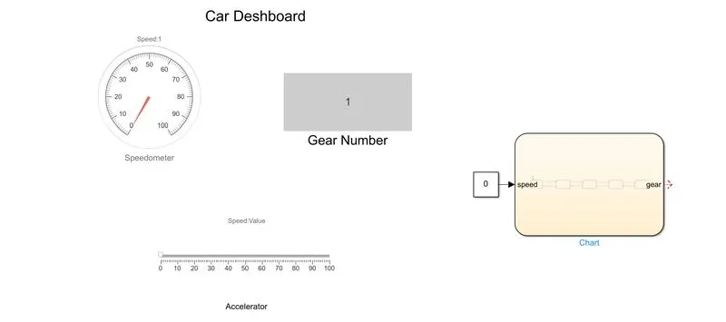
- In this Gear Shift Logic Model we create chart with gear shift display, Speedometer and Accelerator.
- This model we create Accelerator using slider.
- This slider range is 0 to 100 so our speed range for this model is 0 to 100.
- This speed is also shown by speedometer in car deshboard section.
- in this model gear is shifted based on speed provided by Accelerator.
- This shifted gear number is shown in Gear Number Display in car deshboard section.
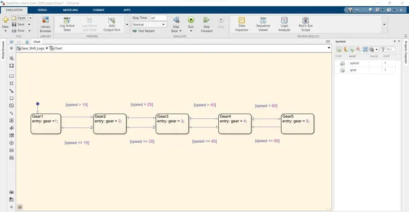
- For this gear shifting process is shown by this chart in fig.
Working
- After completing all the process we start simulation in infinite time mode.
- After starting simulation gear shifting process is shown hear.
- For speed range from 0 to 15 first gear is active.
- This gear is shown in Gear Number display.
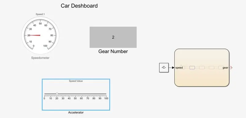
- For speed range from 16 to 25 second gear is active.
- This gear is shown in Gear Number display.
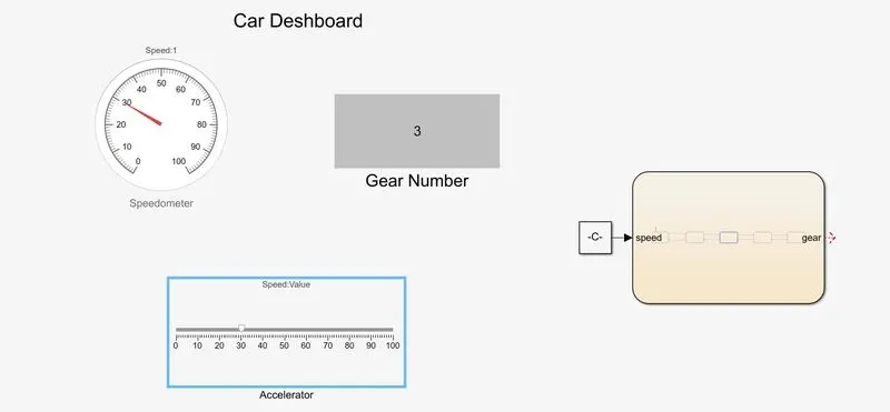
- For speed range from 26 to 40 third gear is active.
- This gear is shown in Gear Number display.
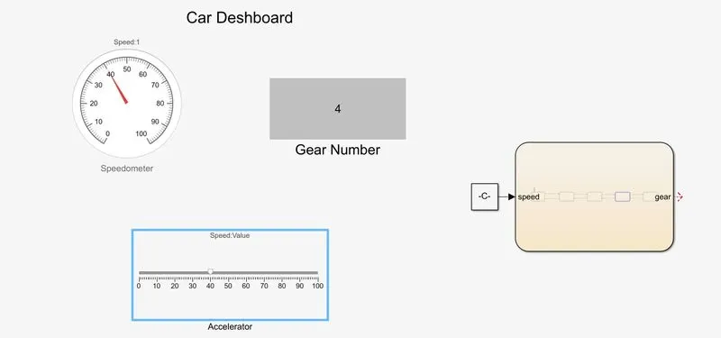
- For speed range from 41 to 60 fourth gear is active.
- This gear is shown in Gear Number display.
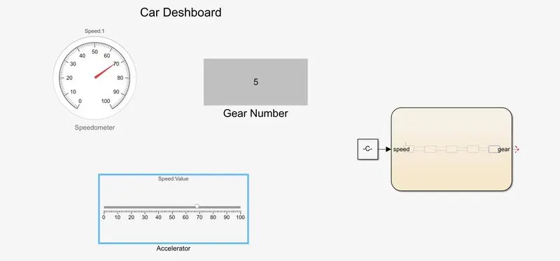
- For speed range is above 61 fifth gear is active.
- This gear is shown in Gear Number display.
Results
- After making this model we learn about gear shift logic of car and other vhicled using stateflow chart.
- We also learn about how to use simulink deshboard blocks.
Simulink file of this Model is atteched to hear, it can be open by clicking this link "Simulink File For Gear Shift Logic"