Week -2
Answers
Q1
Objective
In this challange we make a simulink model of old style electromagnetic Doorbell and analysis movement of plunger whene battery voltage is apply.
Explaination
Explaination
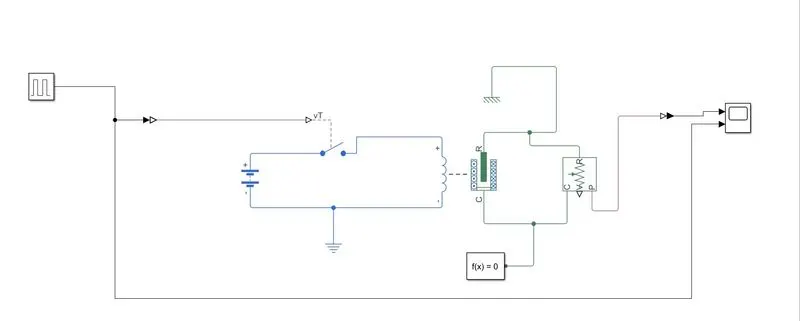
- For making simulink model of electromagnetic Doorbell we first use solenoid block
- After placing solenoid block study parameter of solenoid block.
- Then operate solenoid electrically we place battery and switch.
- After completing this circuit place Ideal Motion Sensore to mesure motion of plunger.
- Output signal of IdealMotion Sensore is provided to Physical System to Simulink converter and after this signal is go to scop for further analysis.
- After completing all of this step provide physical signal to switch for open and close electrical circuit.
- For generating this signal use Signal Generator block and Simulink to Physical System Converter.
- By using this blocks we produce physical signal of on and off for electrical switch.
- After completing all the process we run the simulation for 10 seconds and analysis the results.
- For the simulink file click hear "Elrctromagnetic Doorbell Simulink File".
Observation
- In the observation we analyze two diffrent cases
- Input voltage is less then rated input of solenoid input.
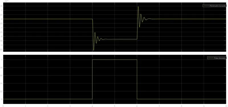
- For input voltage is less then rated input voltage plunger movement is shoen in the fig.
- For low input voltage elctric current is low.
- Because of low electric current electromagnetic force is low so oscillation is created in plunger in both on and off condition.
- Input voltage eqaual to rated input of solenoid input voltage.
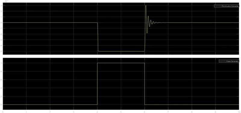
- For input voltage is equal to then rated input voltage plunger movement is shoen in the fig.
- For rated input voltage elctric current is sufficient to produce requred amount of electromagnetic force.
- Because sufficient electromagnetic force oscillation is created in plunger in only free side.
Q2
Objective
Disign of simulink model for temprature controlled fan.
Explaination
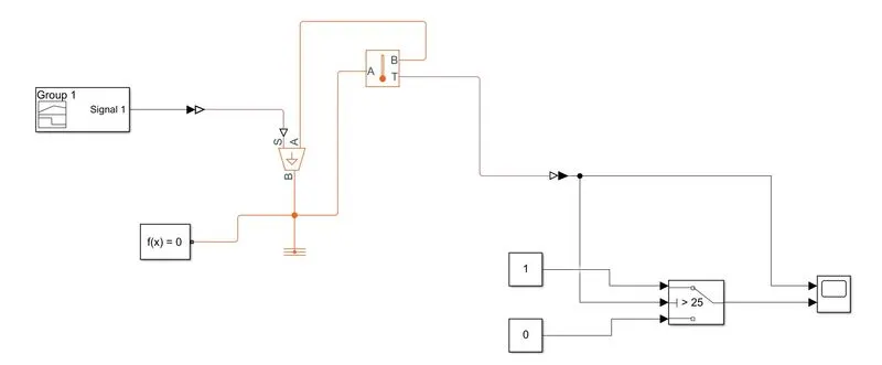
- For making this model we use signal builde block and make temprature signal from given data.
- After generating signal this signal is converted to simulink to physical system converter
- Then this signal is fed to controlled temprature source.
- This temprature source is connrctrd between thermal refrence and temprature mesurment.
- For mesuring this temrature we use temprature mesurment block.
- mesured temrature signal is fed to physical system to simulink converter.
- After converting this signal, signal is fed to switch.
- This switch is work as a comparator.
- When input temprature value is above 25 degree celcius then switch turn on the fan.
- For the simulink file click hear "Temprature Controlled Fan Simulink File".
Results
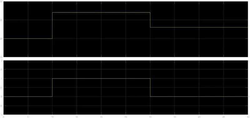
- Resuts are shown in this fig.
- when temprature is above from desired value fan is on.
- when temprature is below disired value fan is off.