Project
Aim
Study system level simulation of an all-terrain vehicle.
Basic Information
- In this model we study about transmission system of vehicle.
- In now days mainly four type of transmission system is available
- Manual Transmission
- Continuous Variable Transmission or CVT
- Semi Automatic Transmission
- Automatic Transmission
- In this Four Type of transmission we study hear only Continuous Variable Transmission.
- The continuous variable transmission is give a smoother driving experiance, Better Fule Efficiency and Stepless Driving Experiance.
- CVT draw maximum engine power of any point of time, so it give quicker acceleration than standard manual or automatic transmission.
- CVT is also light weight than other traditional transmission system.
Explaination of all cases
- In this project we have to study four diffrent cases
- Study the baja ATV model without dashboard.
- Study the baja ATV model with dashboard.
- Study the baja ATV model using lookup table without dashboard.
- Study the baja ATV model using lookup table with dashboard.
Case 1
Explaination
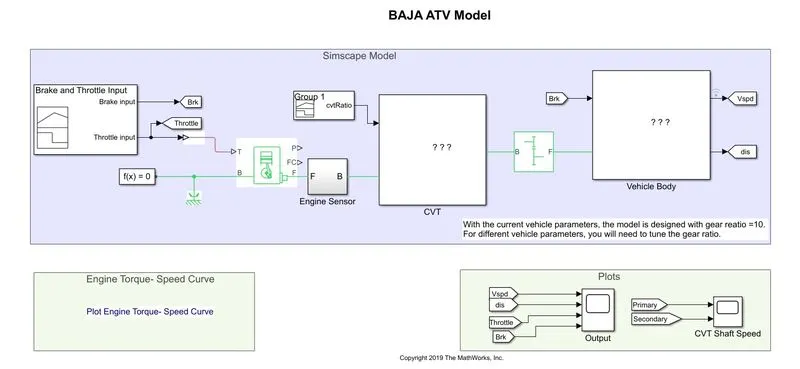
- In this case we study baja ATV model without dashboard.
- In this model we use Signal builder, Generic Engine, Motion Sensore, Vehicle Body, Vehicle Transmission System, Scop etc.
- This model has CVT subsystem and vehicle body subsystem which shown in fig.
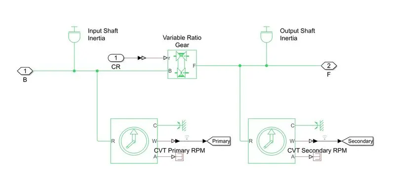
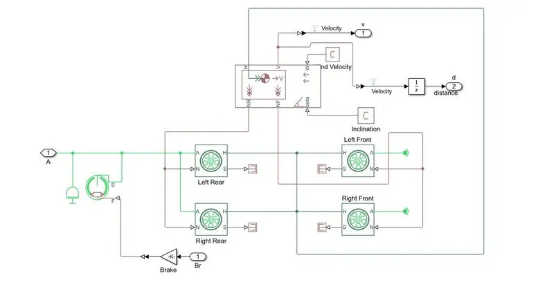
- In this model initial engine speed is 2100 rpm.
- Mechanical rotation of Driven & Driving pully is 0.8 & 0.7 respectively.
- In this case mass of vehicle is 250kg and 2 axles 4 wheel system is used.
- In this system we provide throttle, brake and gear ratio using signal builder block.
- In this case throttle input is 0.3 for 20s and increases to 1 for all time of simulation.
- The brake value is 0 for overall simulation.
- In this case gear ratio is 2.3 for 5s therfore it linearly decrease to 1.8 and after it maintain constant for overall simulation.
Results
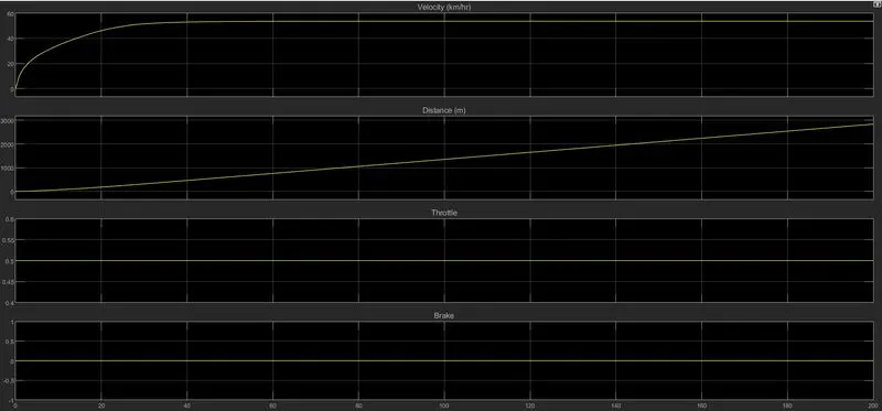
- This fig shows four diffrent signals which is Velocity, Distance, Throttle and brake.
- The value of throttle is simmilar to throughout the simulation.
- Velocity is increse 0 to 50 in 40s because of inrtia of vehicle body.
- brake input is 0 through out the simulation.
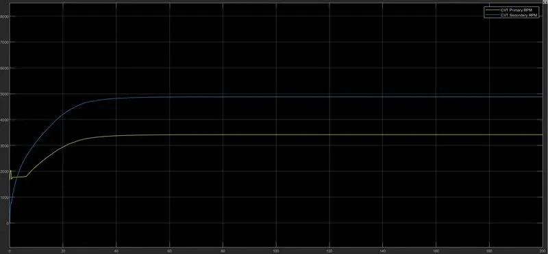
- This fig is shows CVT Primary and CVT Secondry RPM.
- In the initial condition CVT Primary rpm is high because high torque is reqired.
- Whene vehicle start moving primary CVT rpm is goes down and secondary CVT rpm is goes up.
Case 2
Explaination
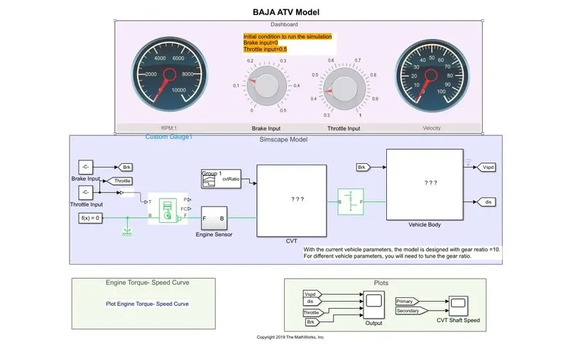
- In this case we study baja ATV model with deshboard.
- In this case we adjust throttle and brake using dashboard.
- Rest of the input like gear ratio is same as baja ATV model without dashboard.
- RPM and Velocity meter is also provided on dashboard.
- In this model we use infinite time simulation so we can set throttle and brake using given pot on dashboard.
- We also see how rpm and velocity is changed by applying input.
- In this model gear ratio is maintain by 2.3 for 5s and linearly decreases to 1.8 after is constant to overall simulation.
- As we seen on running simulation we increase throttle rpm and velocity is increase.
- When brake is apply velocity is decreases.
Results
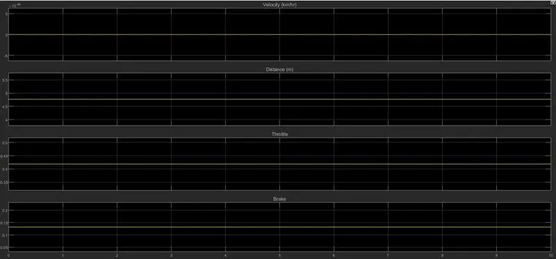
- In this graph four diffrent signal is shown.
- Which os Velocity, Distance, Throttle and Brake.
- As the shown in result we change throttle value velocity is goes up.
- When Brake is apply velocity is goes down.
Case 3
Explaination
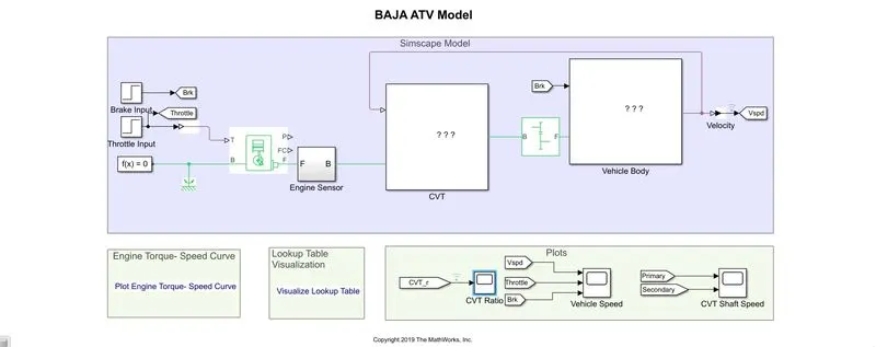
- In this case we use baja ATV model using lookup table without dashboard.
- In this model we use Generic Engine, Vehicle Transmission System, Vehicle Body, Configuration block etc.
- Vehicle body subsystem is shown in this fig.
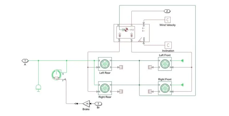
- In this model we simulate model using step time method.
- In this model two subsystem are present which is CVT subsystem and vehicle subsystem
- As the shown in fig CVT subsystem includes look up table.
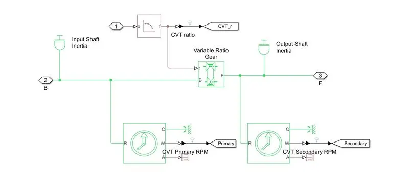
- The initial engine speed is given as 2100 rpm.
- Mechanical rotation for driven and driver pully as 0.8 & 0.7 respectively.
- The mass of vehicle is 250kg and it works on 2 axle 4 wheel arrengment.
- In this model brake input and throttle input is given by step input.
- brake input is remain 0 througout the simulation but throttle value is initial 0.3 and after 35s it goes up to 1.
- For CVT ratio we use lookup table which provide input gear ratio to CVT block.
- This method is very effective which can avoid the unusual torque at the certain speed and very easy to achive greater velocity & engine speed.
- In this model gear ratio is vary from 2.3 to 1.8.
- In this model maximum velocity is achived by 57kmph approximately.
Results
- In this model we use lookup table as a gear ratio input.
- This input value of CVT ratio, Throttle Value and Brake is shown in fig.
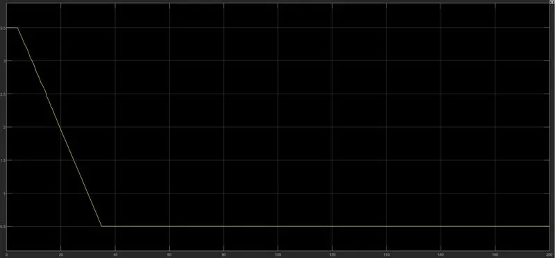
- Whene we start simulation we input throttle and brake value.
- As a result velocity of vehicle is increse or dectrease.
- This result is shown in fig hear.
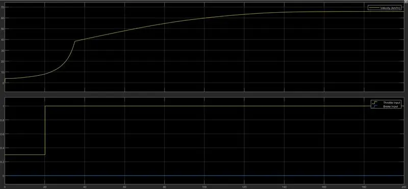
- As we seen in the graph we increase throttle value velocity of vehicle is increase.
- brake value is remain 0 through out the simulation.
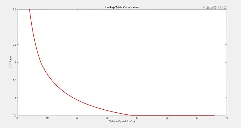
- This fig shows a CVT ratio changed according to output.
- Whene Vehicle speed is low CVT ratio is high because of high torque demand.
- Whene Vehicle speed is high torque demand is low so CVT Ratio is also low.
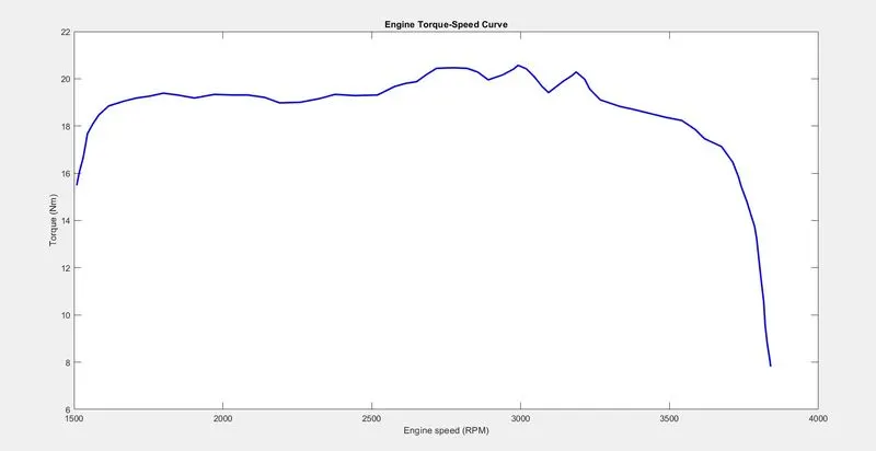
- In the above fig shows a Engine Torque-Speed Curve.
- This graph shows that whene engin speed is high torque is low.
- Whene engine speed is low torque is high.
Case 4
Explaination
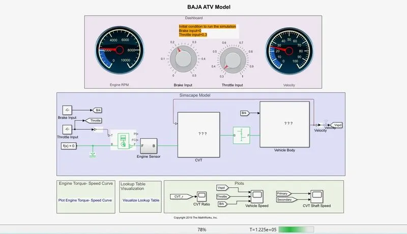
- In this case we study Baja ATV with dashboard model using lookup table.
- This model consist rpm and velocity meter and brake and throttle input in dashboard.
- Rest of the system is common as the above baja ATV model without dashboard.
- The main concept of this model is study output when we vary the input parameter throttle and brake.
Results
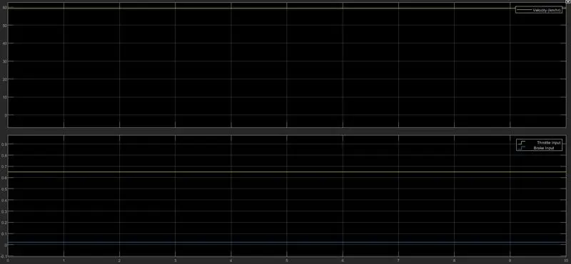
- In this model results are same as a Baja ATV model mapped without dashboard.
- oOnly diffrence is hear we changes throttle and brake value in simulation and observe output.
Conclusion
- By simulating this four model we learn about how to Continuous Variable Transmission System work.
- As a conclusion we say that when throttle value is increase engine poewer is increase and then velocity of vehicle are also increase.
- Gear ratio is continuously increse or decrese based on torque demand and throttle or brake input.
- Whene brake is apply value of velocity is decrease and engine power is also decrease.