Week - 4
1. AIM : To implement control logic of a “washing machine” using Stateflow as per given sequence :
- If the power supply is available, the system gets activated
- If the Water supply is not available, stop the process & indicate through LED
- Soaking time should be 200s followed by Washing time of 100s.
- Then rinsing happens for next 20s & dryer runs for 50s
PROCEDURE :
- Start simulink and create a blank model.
- Search for chart block in the stateflow category of library browser.
- Open the chart block and select the state and junction feature from the stateflow window.
- We then developed the Control logic for washing m/c is such that it should soak the water for the first 200sec followed by washing time of 100sec.Rinsing the water for the next 20sec followed by drying time of 50sec.
- After finishing the control logic run in the STATEFLOW and check the sequence of operation for 500 sec.
Block diagram :
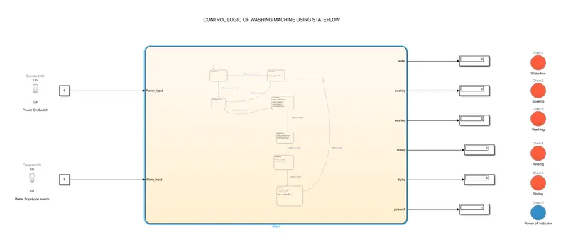
Blocks used:-
- Toggle Switch for power on and off function and one for water supply on and off unction
- Constant block is given as input to the chart for toggle switch
- Chart wherein logic is developed using states and junction for developing stateflow
- Display is given to display the output of which state is active
- Lamps are used as indicators of the state executed during that interval
Development of Washing Machine logic in Stateflow:-
Stateflow chart:-
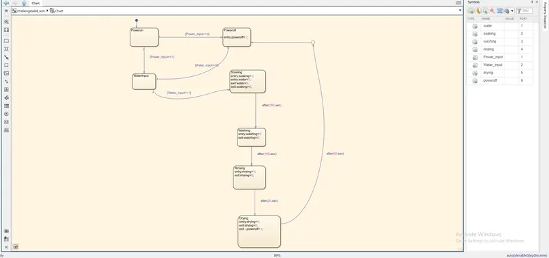
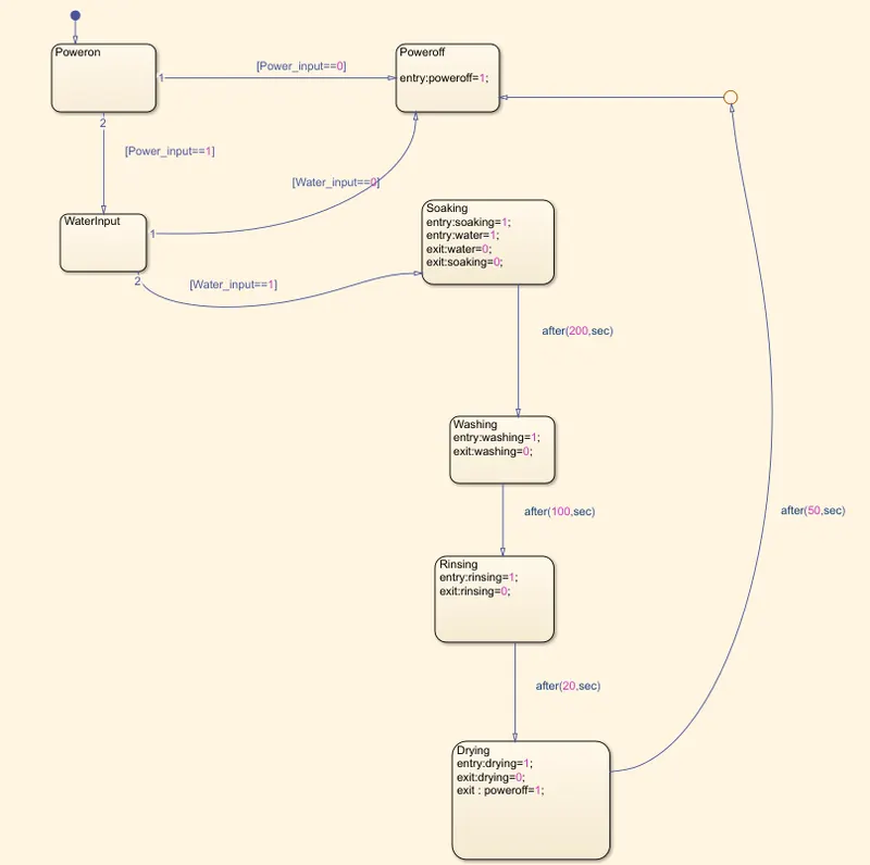
- First we created the states Poweron, Poweroff and WaterInput using state block in stateflow chart and gave transition conditions from Poweron to Poweroff state as [Power_input==0] which signifies if their is no power it will show a swithched off stateof washing machine.
- Also, we gave [Power_input==1] as transition condition between Poweron state and WaterInput state , which indicates if lectric supply is present it will check for water supply state . If water supply is not present then the WaterInput state will transistion to Poweroff state to switch of the washing machine using [Water_input==0] transition condition.
- If water supply is present then WaterInput state will transition to Soaking state satisfying condition [Water_input==1] after which waterflow and soaking in the washing machine in simultaneously carried out. In the state we have give outputs during soaking state using entry:state=1 and exit:state=0 syntax wherin 1 state means it has to carry out the process during entry and 0 means it will have to process while exiting the state
- For it to transistion to Washing state we gave condition " after(200,sec) " which means soaking state will go on for 200 seconds after it's commencement after which it will move to washing state which will be carried out for 100seconds using same after(time,sec) syntax and then similarly it will continue rinsing state for next 20 seconds and then it will move to drying state for 50 seconds wherein our cycle ends and it will proceed to switchoff the machine . We used junction here to give the input to power off state which will make the lamp glow blue of power off indicator signyinfying the end of cycle and the machine will proceed to switch off.
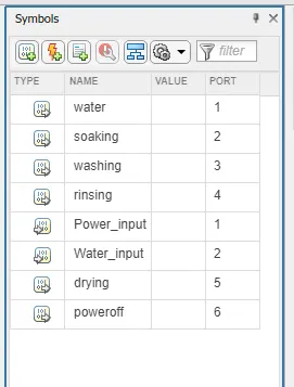
- In the symbols pane the type of datas were defined, wherein we have 6 output datas for poweroff output , water output , soaking process output, washing process output , rinsing process output , drying process output are defined.
- Also 2 input datas for Power_input and Water_Input is defined.
- The port number in the pane defines the order of position of each ports.
- The output from the each process is displayed and is connected with individual lamps to indicate what process are completed.
- The number 0 indicates there is no flow of cycle and is indicated in RED colour.
- The number 1 indicates there is flow of cycle and is indicated in GREEN colour apart from Poweroff state which will glow blue indicating machine is switching off or will not power on.
- Each lamp is connected separately with the output from each stage of the cycle.
- As we can see in the below images that for each output state we have defined color indication for 0 and 1 as red and green respectively indicating if the process is active or inactive . If it is 0 and red color it means process/state is currently not active and if green which indicates process/state is active.
- For Poweroff lamp we have given blue color if condition is true with value 1.
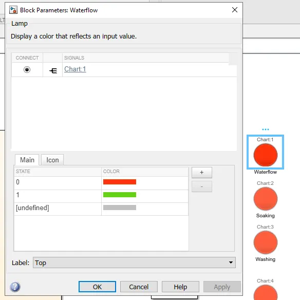
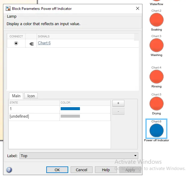
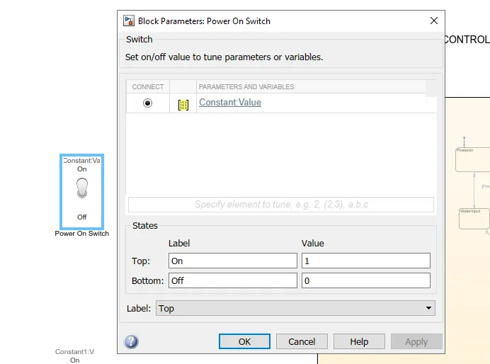
- Two toggle switches were connected with the input constants , one for power and other for water respectively.
- Where for ON condition gives 1 is and for off condition gives 0 signifying active and inactive condition.
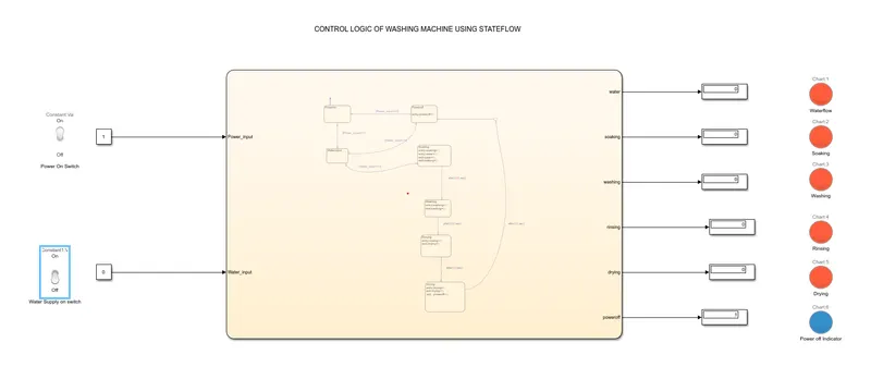
The washing machine model is simulated for a run time of 500 secs.
Also, as we can see from below image if water input is off it will proceed to switch off the washing machine
CONCLUSION: We have succesfully implement control logic of a “washing machine” using Stateflow as per given conditions.
********************************************************************************************************************
2. AIM: To make a Simulink model for the “Gear shift” using Stateflow to implement the logic as per given conditions:
For, given speed range the gear value
- Speed Range(kmph) Gear
0 to 15 1
16 to 25 2
26 to 40 3
41 to 60 4
Above 61 5
- Give speed input while the simulation is running & display the gear number for that speed.
PROCEDURE:
- Start simulink and create a blank model.
- Search for CHART block in the stateflow category of library browser.
- Open the chart block and select the various features from the stateflow window.
- Control logic for gear shift is such that it should change the gear when the speed increases of decreases automatically which in our model is implemented using slider block.
- After finishing the control logic run the stateflow and check the gear shift operation for an infinite time.
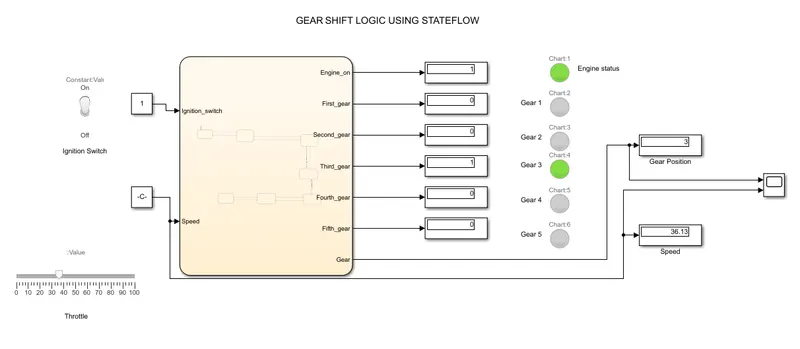
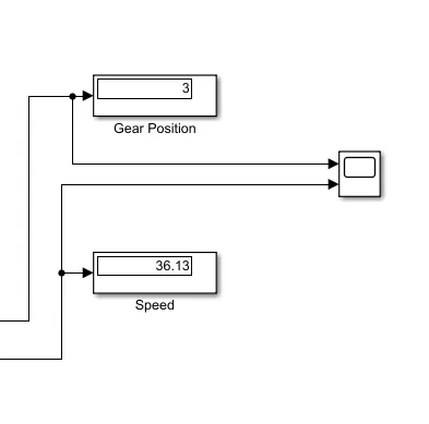
- We have aso used display for the current gear and speed and used scope to plot the values against each other for changing speeds.
Block Diagram:
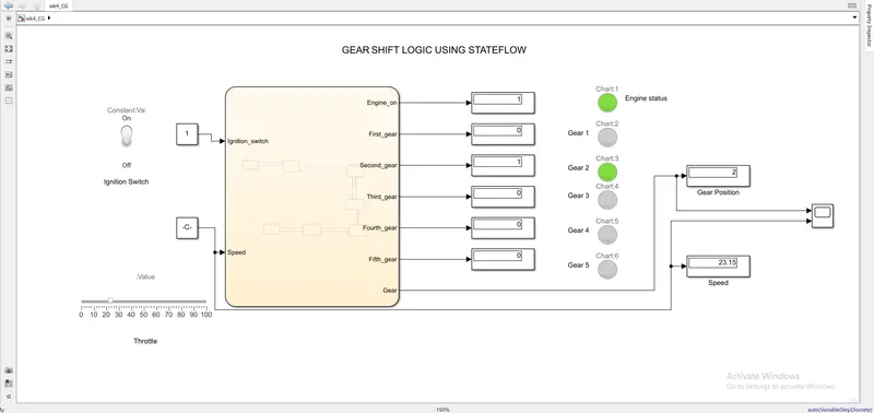
Blocks Used:
- Toggle Switch is used to switch on and switch off the engine.
- Slider is used to act as throttle to change the speed of the vehicle
- Constant block is used to provide inputs the state acting as intermediary for slider and ignition switch.
- Chart wherein logic is developed using states and transitions for developing stateflow
- Display is used to display which state is active and also to capture speed and gear positions respectively.
- Scope is used for graphical comparison between gear position and vehicle speed.
- Lamps are used as indicators of the state executed during that interval
Development of Gear Shift logic in Stateflow:
Stateflow Chart:
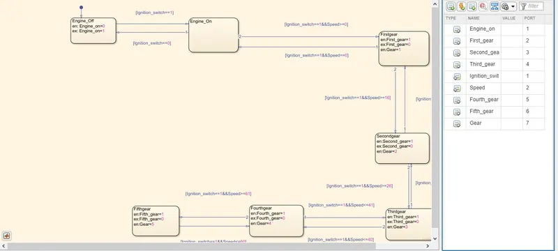
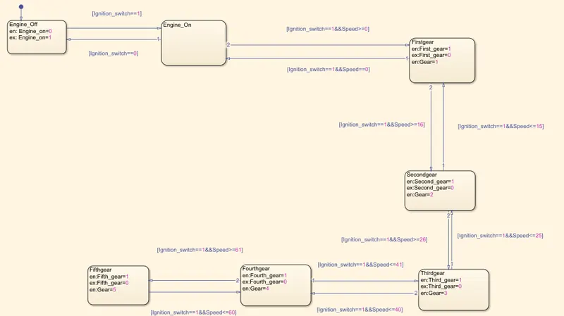
- Firstly, we import the chart block and double right click on it to create stateflow logic within the chart block.
- Then we define states such as Engine_off wherein "entry" syntax and "exit" syntax also denoted as en and ex represents entry and exit condition from the state. If it is 0 on entry means the ignition switch is off and if engine will not start . It will transistion from Engine_off state to Engine_on state with condition [Ignition_switch==1] during exit if ignition switch is in on and engine will start.
- After Engine_On state is satisfied it will transistion to next state when vehicle moves from rest with transition condition[Ignition_switch==1&&Speed>=1] i.e if the vehicle moves from rest and gains speed greater than 0 kmph than gear will shift from neutral to 1. Similarly if it will exceed speed greater than 15 it will shift to second gear and if vehicle speed increases to more than 25kmph it will go in third gear and similarly if it exceeds 40kmph it will go in fourth gear and when it crosses 60 kmph it will go in fifth gear. This was true when vehicle increases.
- We know that vehicle speed will vary, it can decrease or increase depending on various external conditions so we should have in place logic to downshift the gears for which we used transistion condition [Ignition_switch==1&&Speed<=60] i.e vehicle speed reduces below 60 it will downshift from 5th gear to 4th gear and applying similar logic to further downshift from 4th to 1st gear and then to neutral to engine off condition using the mentioned transistion logic depending on the condition provided.
- Also en signifies the entry signal which will make the state active if it is 1 and inactive if it is 0 also en:Gear signifies the current Gear engaged. Also ex states the output signal to the next state and signifying previous state condition which it left.
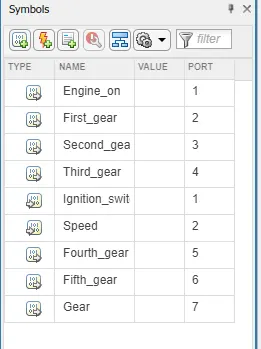
- In the symbol pane two inputs i.e Ignition_switch and Speed and the rest as output i.e Engine_on which tells whether engine is on or off , First gear, Second gear, Third gear, Fourth gear, Fifth gear and Gear which tell the current gear position.
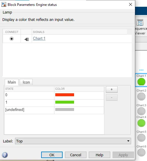
- We have connected Lamp with displays next to each output which has red and green for 0 and 1 as input wherein 0 indicates it is not in that state and 1 states that the state is active. Threfore green is for active and red for inactive .
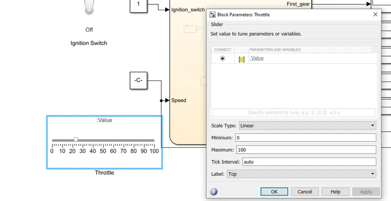
- A simple slider is added from the library and is connected with the constant directly.
- By moving the slider named as throttle we can change the speed instead of manually entering the numbers in th constant block.
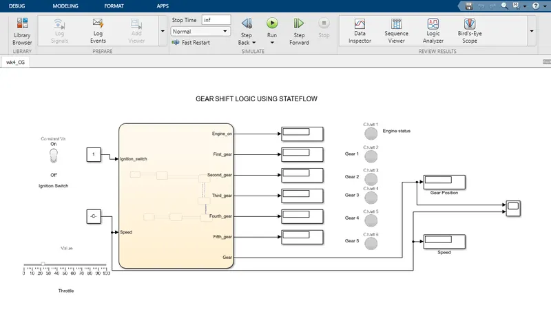
- For a period of time the file is compiled with the time limit as infinity (inf).
- While compiling the speed is altered with the help of slider for time gap intervals and the graph is recorded in the scope block.
- The plot is generated for both speed input and gear position output in the display separately.
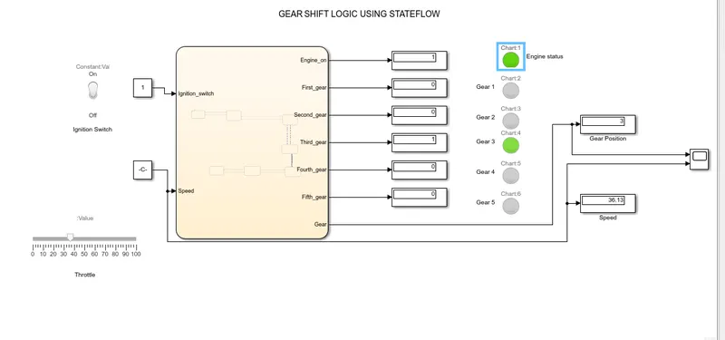
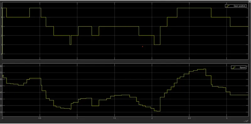
The above plot shows how with respect to change in speed the gear shift is happening.
i. Also , we have attached display for measuring speed and a display to give respective gear position output
CONCLUSION : Thus, we have developed a gear shift logic stateflow in simulink as per the given conditions and have also displayed the correct gear ratio for the corresponding speed during simulation.