Week - 4
TASK-1
IMPLEMENT CONTROL LOGIC OF WASHING MACHINE USING STATE FLOW
AIM: To Create a model to implement control logic of washing machine using state flow.
OBJECTIVE: To Create a model to implement control logic of washing machine using state flow with the following state conditions.
- If the power supply is available the system gets activated.
- If the water supply is not available, stop the process and indicate through LED.
- Soaking time should be 200s followed by washing time of 100s.
- Then rinsing happens for next 20s & dryer runs for 50s.
MODEL:
https://drive.google.com/file/d/1K9T5EUyEQeucjFhDLIj-8hWkGhzRd2qi/view?usp=sharing
PROCESS:
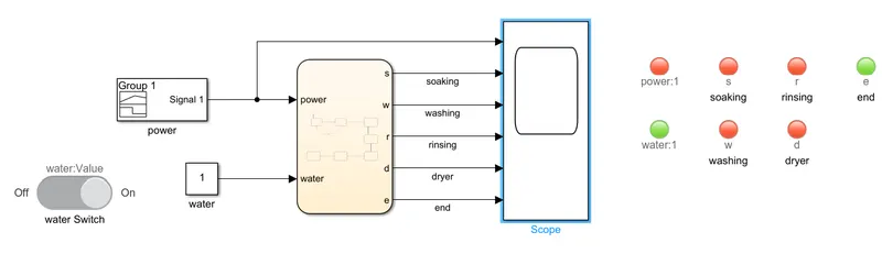
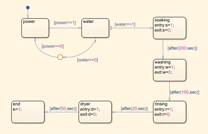
- In this model we used chart block to define the different states and time delays for the states.
- For the state-1 we gave the state name as Power and condition as Power==1 it means if there is a power supply available it moves to the next state.
- For the state-2 we gave the state name as Water, in this state it checks for the water supply availability.
- If the water supply is available, it performs the condition Water==1 and moves to the next state, if there is no water supply condition will be Water==0 then process will stop
- For the state-3 we gave the state name as Soaking, and entry, exit values as S=1, S=0
- This state will operate for 200sec as we given the time delay of 200sec with the condition after(200,sec) so after 200sec it will move to the next state.
- For the state-4 we gave the state name as Washing, and entry, exit values as W=1, W=0
- This state will operate for 100sec as we given the time delay of 100sec with the condition after(100,sec) so after 100sec it will move to the next state.
- For the state-5 we gave the state name as Rinsing, and entry, exit values as R=1, R=0
- This state will operate for 20sec as we given the time delay of 20sec with the condition after(20,sec) so after 20sec it will move to the next state.
- For the state-6 we gave the state name as Dryer, and entry, exit values as D=1, D=0
- This state will operate for 50sec as we given the time delay of 50sec with the condition after(50,sec) so after 50sec it will move to the next state.
- After completion of all the it will enter the End state and the process will end.
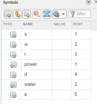
- In the symbol pane we defined the power and water as input data type and S, W, R, D, E as output data types.
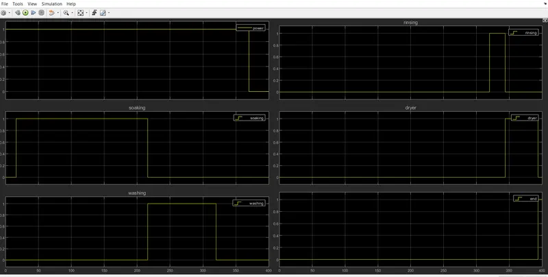
- We used Signal builder block to generate a signal for input power supply by keeping the amplitude at 1 for 370 sec as it requires 370sec for the washing machine to come to end state, and the amplitude at 0 for time period of 370-400sec to observe the OFF-state condition of washing machine.
- We used the constant block connected to a slide switch, for the water supply.
OUTPUT:
OBSERVATION:
- After running the above control logic for washing machine we can observe the different state ON-OFF conditions by using the LED indicators
- We can observe the END state LED is green after the process is completed.
TASK-2
SIMULINK CHART FOR THE GEAR SHIFT LOGIC
AIM: To model a Simulink chart for the gear shift logic.
OBJECTIVE: To create a Simulink chart for gear shift logic as per the given speed ranges and display the gear number.
Speed range (Kmph) Gear
0 to 15 1
16 to 25 2
25 to 40 3
40 to 60 4
Above 60 5
MODEL:
https://drive.google.com/file/d/16rvfs-plu_NxmaOf5k1eMa4Onb-UVNiI/view?usp=sharing
PROCESS:
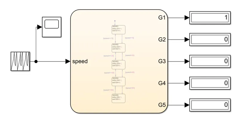
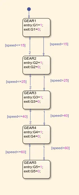
- In this model we used chart block to define the states and the conditions.
- In the chart block we used state block to define the gears from 1 to 5.
- For the state-1 we gave the state name as GEAR1 and entry and exit values as G1=1, G1=0 respectively.
- we gave the conditions as if speed > 15 it goes to next state if speed <= 15 it operates in the same state i.e., GEAR1.
- For the state-2 we gave the state name as GEAR2 and entry and exit values as G2=1, G2=0 respectively.
- we gave the conditions as if speed > 25 it goes to next state if speed <= 25 it operates in the same state i.e., GEAR2.
- For the state-3 we gave the state name as GEAR3 and entry and exit values as G3=1, G3=0 respectively.
- we gave the conditions as if speed > 40 it goes to next state if speed <= 40 it operates in the same state i.e., GEAR3.
- For the state-4 we gave the state name as GEAR4 and entry and exit values as G4=1, G4=0 respectively.
- we gave the conditions as if speed > 60 it goes to next state if speed <= 60 it operates in the same state i.e., GEAR4.
- For the state-5 we gave the state name as GEAR5 and entry and exit values as G5=1, G5=0 respectively.
- we gave the conditions as if speed > 60 the state GEAR-5 will operate.
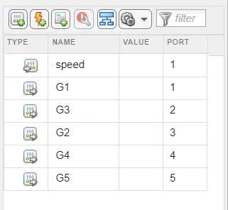
- In the symbol pane we defined the speed as input data type and G1 to G5 as output data types.
- We used repeating sequence block to generate a varying speed signal.
- We gave the varying speed signal from repeating sequence block to the gear shift logic chart.
OUTPUT:
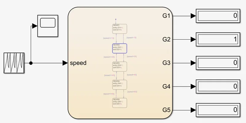
For condition 0-15kmph: vehicle operates under GEAR1.
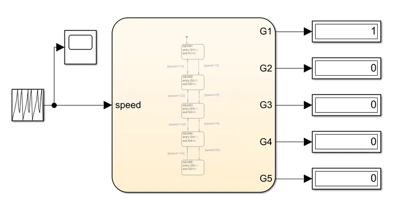
For condition 16-25kmph: vehicle operates under GEAR2.
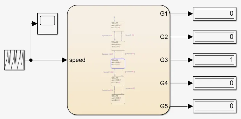
For condition 26-40kmph: vehicle operates under GEAR3.
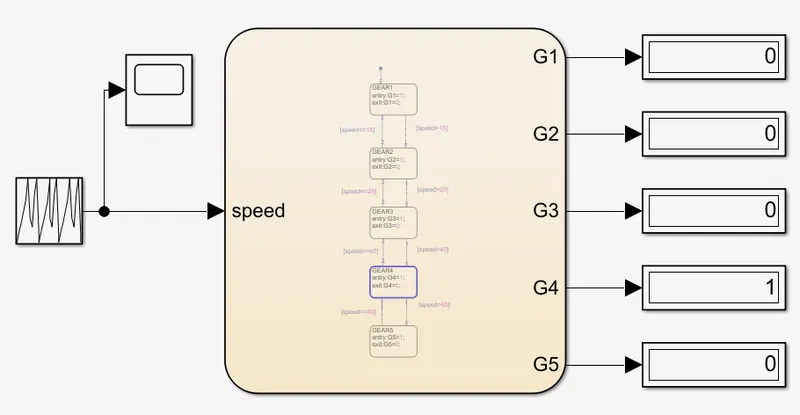
For condition 41-60kmph: vehicle operates under GEAR4.
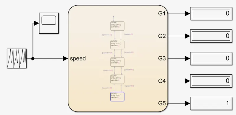
For condition above 60kmph: vehicle operates under GEAR5.
OBSERVATION:
- After running the above logic chart for run time of 100 sec we can observe the change in gears from G1 to G5 with respect to the speed by using the display block at the output port of the chart block.