Week - 4
PART A
AIM: Make a Simulink model of a washing machine using state-flow as per the given sequence.
OBJECTIVE:
- Implement control logic using state-flow as per the given sequence:
- If the power supply is available turn on the system.
- If the water supply is not available stop the process and indicate through the LED.
- Time taken for each process should be as follows:
-
PROCESS Time(seconds) Soaking 200 Washing 100 Rinsing 20 Drying 50
-
- After all the process Turn on the “finished” LED.
THEORY:
WASHING MACHINE
- A Washing machine is a home appliance used to do laundry, the user generally adds the laundry and detergent,
- The operation of the washing machine can be:
- Semi-automatic:-some Some of the steps are done automatically(washing)and some are manual(filling with water, etc).
- Automatic:-All the process of washing is done automatically by the washing machine itself the user only needs to be put in laundry and detergent.
- There are mainly two types of washing machines:
- Frontload: A front load washing machine is a fully-automatic washing machine that loads from the front side. These machines usually consume less water and energy, and usually yield better laundry results than their top-load counterparts.
- Top load: Both manual washing machines and fully-automatic washing machines come in a top load form. These kinds of machines are loaded from the top. They usually take up less space, they fit a washing machine into a narrower space, and use more water and electricity.
MODEL:
- SIMULATION MODEL
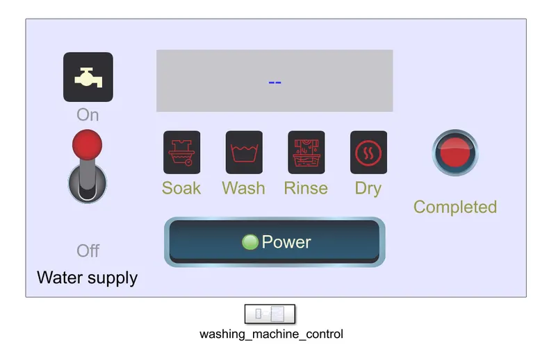
PROCEDURE/EXPLANATION:
- Blocks used:
- Washing machine :
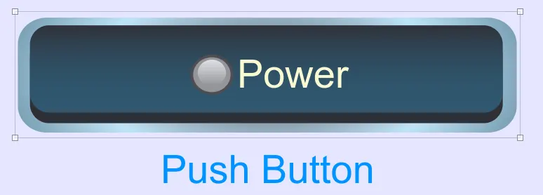
- Push Button: Used to switch on or off the power supply for the washing machine
- OFF:
 ON:
ON:
- OFF:
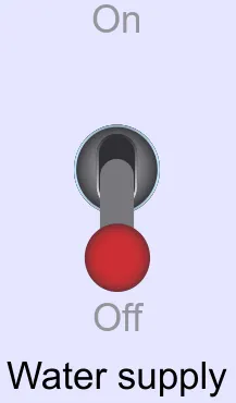
- Toggle Switch: Used for the water supply for the washing machine.
- OFF:
 ON:
ON:
- OFF:
-
Customizable LAMP: Used to create a custom ICON lamp to display the machine states.
- Water supply
- OFF
 ON
ON
- OFF
- Machine OFF
- Machine States 'Inactive(Red)'
- Machine States "ongoing(orange)"
- Machine States 'Completed(green)"
- Water supply
- Display: Used to show current machine status.

 .ETC.
.ETC.
- Push Button: Used to switch on or off the power supply for the washing machine
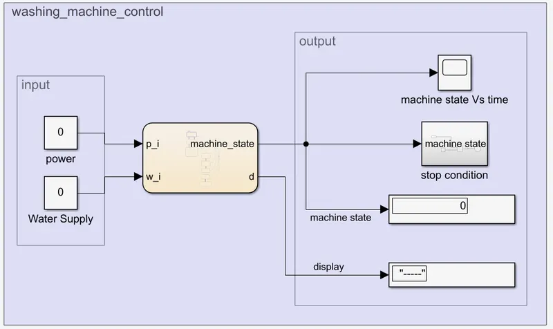
- Washing machine control subsystem:
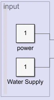
- Constant: Used as the input to control the power and water supply states by connecting them with the switches.
- Chart: Used to build the control logic using Stateflow:
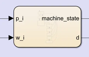
- STATE-FLOW CHART
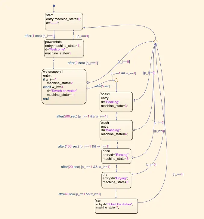
- the inputs are power and water supply
- the outputs are machine_state and 'd'(to display)
- machine-state stores the value corresponding to the current process going on in the stateflow and uses it as a means to communicate with the washing machine display.
- after(time,unit) is used to create a delay between each states as per the requirement.
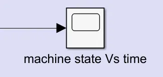
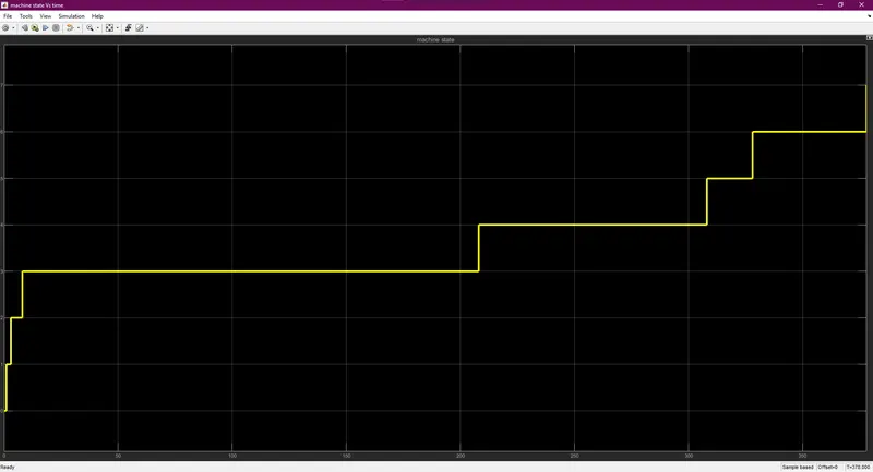
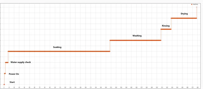
- Scope: used to display the machine state with respect to the time of the simulation
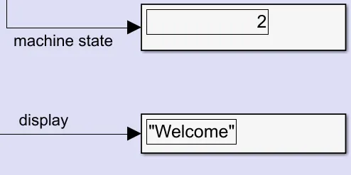
- Display: Used to display the machine state and messages for the washing machine display
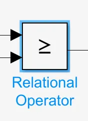
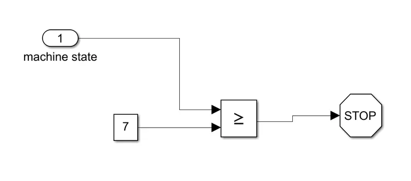
- Relational operator: checks the condition (greater than or equal to) with the input signal and a constant(7) and gives an output signal if the conditions satisfied.
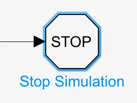
- Stop simulation: stops the simulation if it receives any input signal.
- Constant: Used as the input to control the power and water supply states by connecting them with the switches.
- Washing machine :
- Control Logic of the “Washing Machine” Using Stateflow:
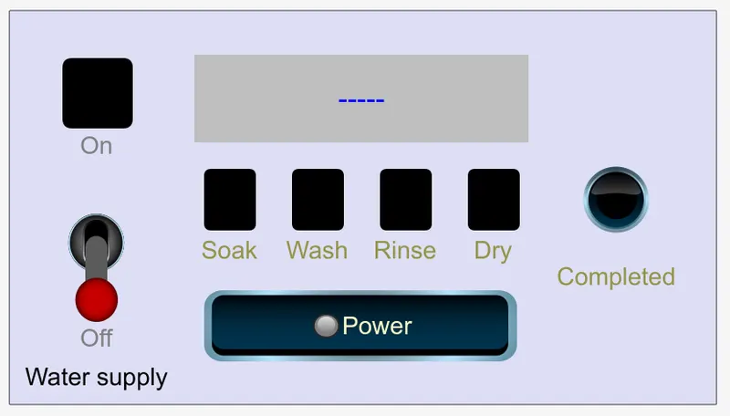
- With power and water at ‘OFF’ condition is shown below. In this condition power supply, water supply, soak, wash, rinse, and dry is under ‘OFF’ condition.
- Power is 0 and water is 0.
- The machine state is 0.
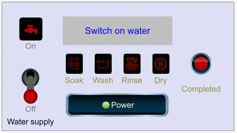
- With power 'ON' and water ‘OFF’ condition is shown below. In this condition power supply 'LED' is in on condition and the water supply, soak, wash, rinse and dry are under ‘OFF’ condition and all LEDs light up 'RED' and a message is displayed to switch on the water supply.
- Power is 1 and water is 0
- The machine state is -1.
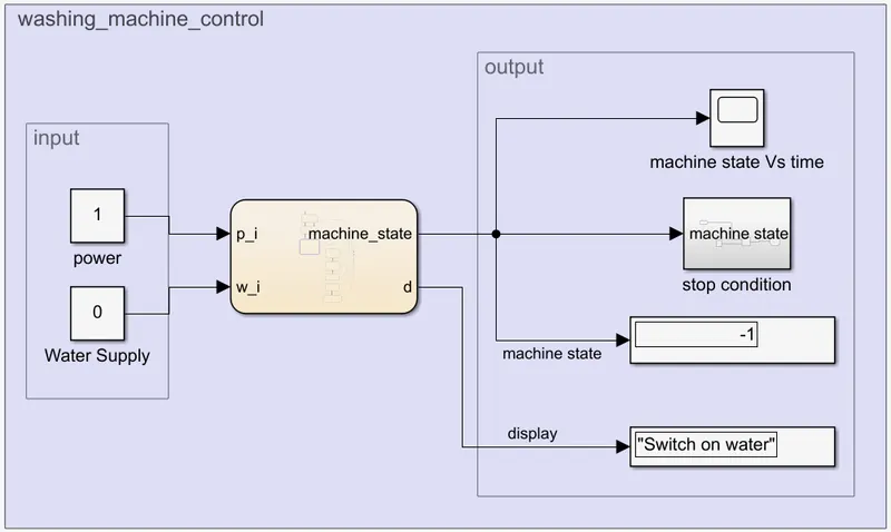
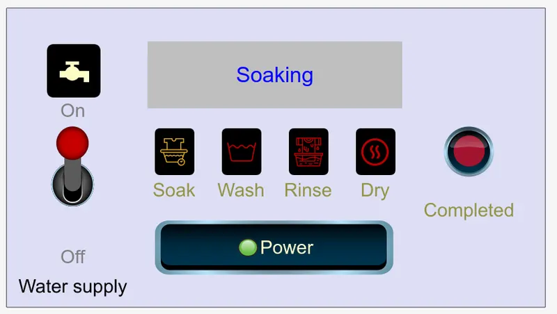
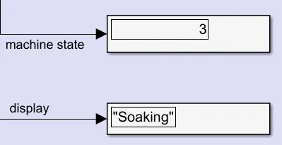
- With the Water supply switched on the Water supply LED turns 'WHITE' and the soaking process starts and the 'SOAK-LED' turns 'ORANGE'.
- Power is 1 and water is 1.
- Machine state is 3.
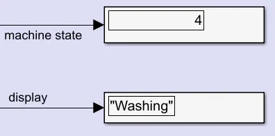
- For 200 seconds the 'SOAK-LED' turns 'GREEN' and 'WASH-LED' turns 'ORANGE'.
- Machine state is 4.
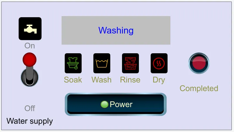
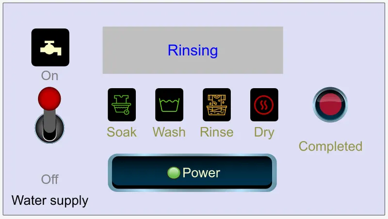
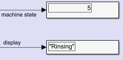
- Next for 100 seconds, the 'WASH-LED' turns 'GREEN' and 'RINSE-LED' turns 'ORANGE'.
- Machine state is 5.
- Next, for 20 seconds, the 'RINSE-LED' turns 'GREEN' and 'DRY' and 'COMPLETED-LED' turns 'ORANGE'.
- Machine state is 6.
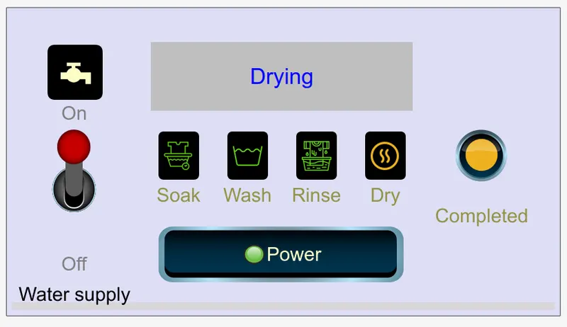
- Next for 50 seconds, the 'DRY-LED' and 'COMPLETED-LED' turn 'ORANGE'.
- Machine state is 6.
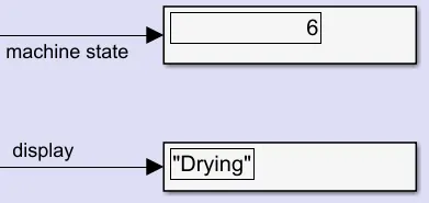
- Next after drying the completed and dry LED turns 'GREEN'
- Machine state is 7.
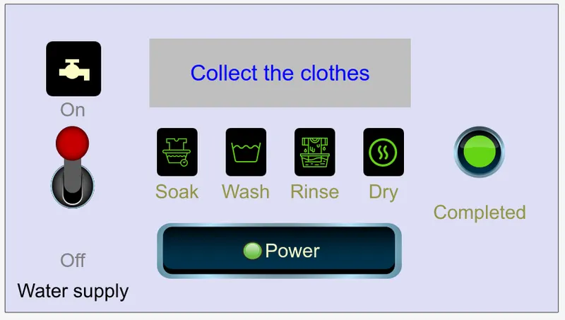
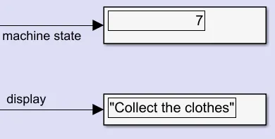
- Once the machine state is 7 the stop condition is 'TRUE' and the simulation stops.
- With power and water at ‘OFF’ condition is shown below. In this condition power supply, water supply, soak, wash, rinse, and dry is under ‘OFF’ condition.




OUTPUT:
- Scope output:
- Machine state Vs time
VIDEO:
- 2X speed :
- VIDEO LINK: https://drive.google.com/file/d/108iZjV4s6Q690pRa8uo7c90T4o46TK_x/view?usp=sharing
- G-DRIVE FOLDER: https://drive.google.com/drive/folders/1-l5RN8Caj2r11O1RCPZ9tVXT-lJ-hZy6?usp=sharing
RESULT: The control logic of a washing machine using Stateflow is implemented satisfying the given conditions and verified.
PART B
AIM: Make a Simulink model of transmission using state-flow as per the given sequence.
OBJECTIVE:
- Implement control logic using state-flow as per the given sequence:
- If the engine is powered then start the system.
- Gear shift for the speed should be as follows:
-
SPEED GEAR 0-15 1 16-25 2 26-40 3 41-60 4 ABOVE 61 5
-
THEORY:
In an automobile a system of gears is used to effectively transmit power from the engine to the wheels via transmission through a gearbox, Most vehicles nowadays has 5-speed transmission, lower gears output high torque and low speed and higher gears output low torque and high speed.
By effectively matching the gear with the speed of the vehicle we can increase the efficiency, lower the fuel consumption, lower the wear on the engine and thus increase the life and reduce the maintenance of running the vehicle.
There are mainly two types of transmissions manual and automatic:
- Manual transmission: the shifting of the gears and matching the speed is done by the driver.
- Automatic transmission: the shifting of the gears and matching the speed is done automatically by a control system.
For this Simulink model, an automatic transmission is modeled with a control logic using Stateflow.
MODEL:
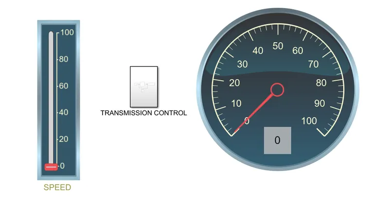
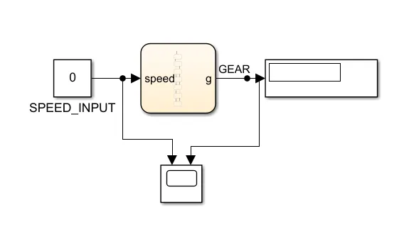
- TRANSMISSION CONTROL SUB-SYSTEM
PROCEDURE/EXPLANATION:
- Blocks used:
- Washing machine :
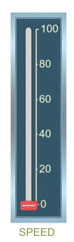
- Customizable VERTICAL SLIDER: Used as the speed input.
-
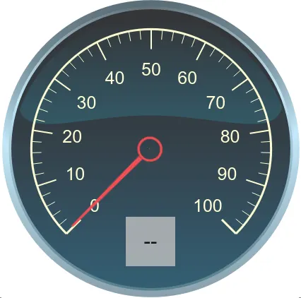
Customizable CIRCULAR GAUGE: Used as the speedometer.
- Display: Used to show current gear.
-
- Customizable VERTICAL SLIDER: Used as the speed input.
- TRANSMISSION CONTROL subsystem:
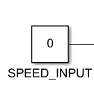
- Constant: Used as the input to control the speed by connecting with the vertical slider.
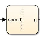
- Chart: Used to build the control logic using Stateflow:
- CHART
- STATE-FLOW CHART
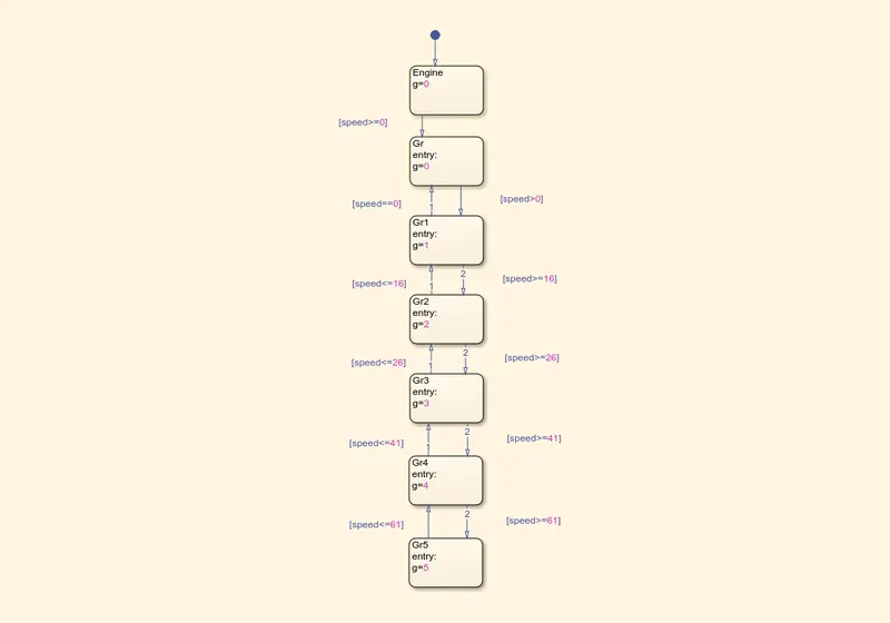
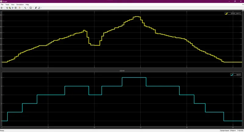
- speed is taken as an input and the gear is displayed as an output.
- conditional statements in which input speed is cross-checked with the given speed to which the gear is to be shifted is checked and the respective gear is the output.
- CHART
- Scope: used to display the Gear and speed values over time of the simulation.
- Display: Used to display gear by connecting it to the display on the gauge.
- Constant: Used as the input to control the speed by connecting with the vertical slider.
- Washing machine :

OUTPUT:
VIDEO:
RESULT: The control logic of gear shift is implemented with the given conditions and verified.