Week - 4
1.
AIM:-
- To implement control logic of a washing machine using Stateflow as per given sequence
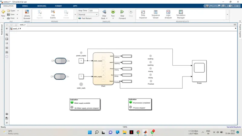
- If the power supply is available the system gets activated.
- If the Water supply is not available then stop the process and indicate through LED.
- Soaking time should be 200s followed by Washing time of 100s.
- Then rinsing happens for next 20s and dryer runs for 50s.
THEORY:-
WASHING MECHINE:-
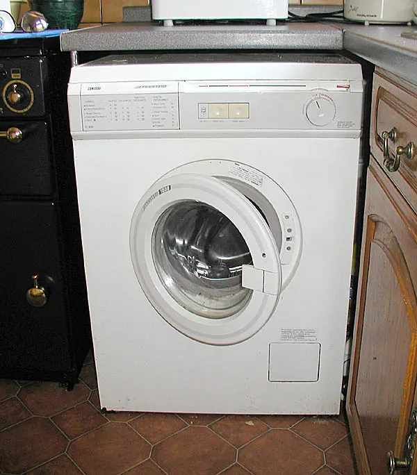
Washing machine is the machine used to wash the various types of clothes without applying any physical efforts. With washing machine you don’t have to rub the clothes with hand or squeeze them to remove the water from them. The washing machine is also called as clothes washer or simply the washer. The washing machine enables you to wash your clothes automatically without having to supervise its operation. All you have to do is put the clothes in the machine and select the wash mode. The washing machine automatically takes in the amount of water and detergent required and it also automatically sets the timer for washing, rinsing and drying as per the selected mode and the amount of clothes.
Types of Washing Machine
Depending on the position of loading the clothes in washing machine, there are two types of washing machines: top loading and front loading washing machines. Both these have been described below:-
1) Top loading washing machine: In this washing machine the clothes are loaded from the top of the washing machine. There is a cover at the top that helps loading and unloading of clothes in the round vessel that perform the function of the washer as well as the rinser and drier in the fully automatic washing machine. The top loading washing machine is preferred by the people who don’t want to bend the body while loading the clothes in the machine. This washing machine is more widely used than the front loading washing machine in many parts of the world.
2) Front loading washing machine: In this machine the clothes are loaded from the front side. The studies have shown that the front loading washing machines consume less electric energy, water and detergent and also give better washing results compared to the top loading washing machine.
OBJECTIVE:-
1. Implement control logic of a “washing machine” using Stateflow as per given sequence:
- If the power supply is available, the system gets activated
- If the Water supply is not available, stop the process & indicate through LED
- Soaking time should be 200s followed by Washing time of 100s.
- Then rinsing happens for next 20s & dryer runs for 50s
After all the processes have completed turn on the finished LED
2. Make a Simulink chart for the “Gear shift” logic as per below conditions:
Speed Range(kmph) Gear
0 to 15 1
16 to 25 2
26 to 40 3
41 to 60 4
Above 61 5
Give speed input while the simulation is running & display the gear number.
SIMULINK MODEL:-
SIMULINK CHART:-
AFTER RUN:-
SCOPE RESULT:-
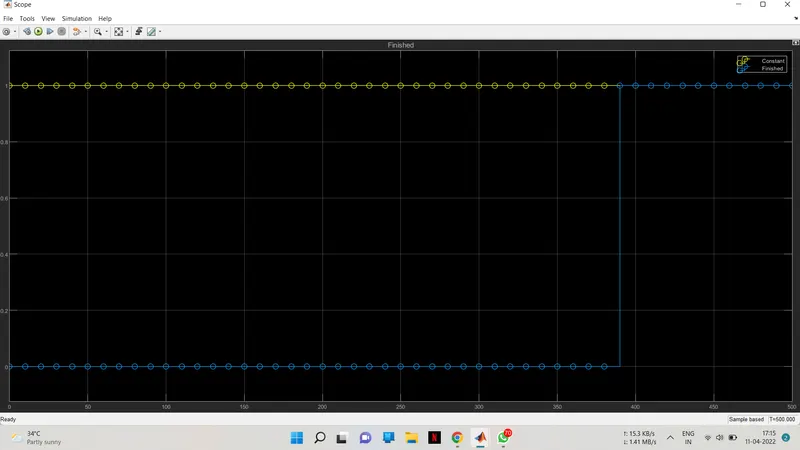
EXPLAINATION OF THE ABOVE IMAGE
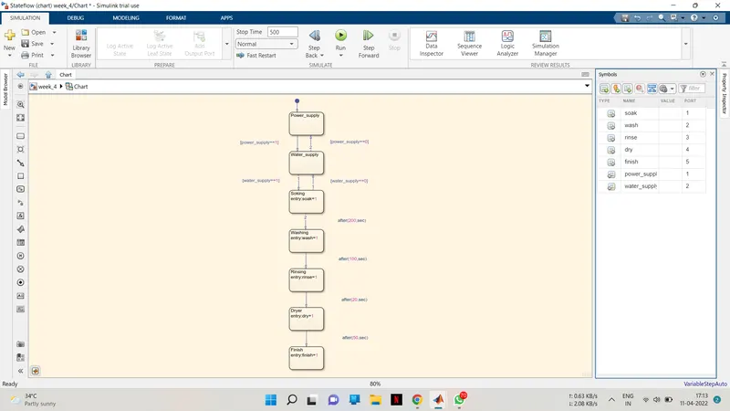
- First the power state is defined if power == 1 then it will go to water state else power == 0 it will go to NoPower state where NoPower = 1 is the entry and when power is not availabel it will display 1 and the lamp will show green else yellow and from there if water == 0 the signal will go to NoWater state state where the entry is NoWater = 1 and when no water is available it will display 1 else 0 and the lamp will show blue color for no water else red.
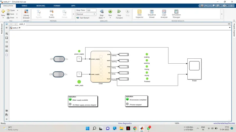
- If water == 1 then the signal will go pass on to next state that is soaking and it will continue for 200 seconds afer it completion display block will show 1 and lamp will reflect green colour.
- After soaking the process will go to next state that is washing only after 200 seconds of soaking and same as above after it completion display block will show 1 and lamp will reflect green colour. It will continue for 100 seconds.
- After 100 seconds washing is completed and the process will move to next state Rinsing it will continue for 20 seconds and afer it completion display block will show 1 and lamp will reflect green colour.
2.
AIM:-
Make a Simulink chart for the “Gear shift” logic as per below conditions:
Speed Range(kmph) Gear
0 to 15 1
16 to 25 2
26 to 40 3
41 to 60 4
Above 61 5
Give speed input while the simulation is running & display the gear number.
THEORY:-
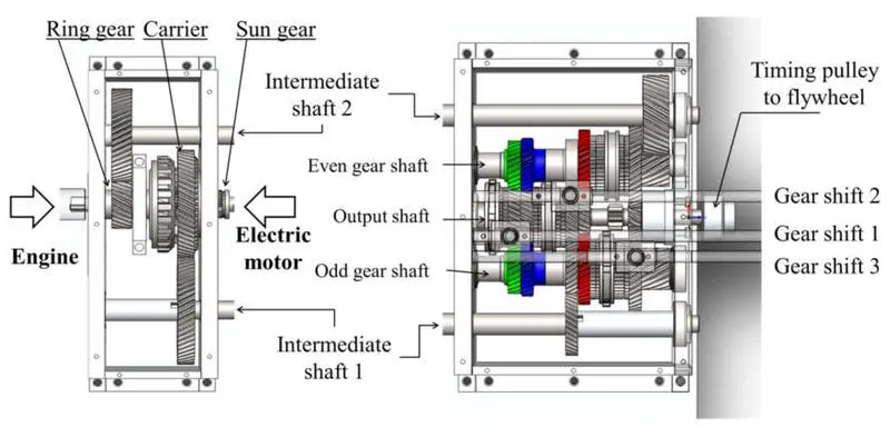
Gear-shift Mechanism Construction
The Gear-shift Mechanism which shifts gears is usually located in the gearbox cover and is driven by a rocker lever. For example, in the gearbox Gear-shift mechanism of a truck, the lever 51 mounted directly on the gearbox swings freely in the spherical socket of the gearbox cover, resting on it with a ball-shaped bulge. The lever is held by a spring and a clamp 50. The lower end of the lever 51 enters in the groove of one of the forks mounted on the sliders 54 and 55.
Five-speed gearbox construction: 1 – drive shaft; 2, 17,22,35,37 and 39 – bearing; 3,21,23,36 – locking rings; 4 and 34 – permanent gearing gears of drive and intermediate shafts; 5 – synchronizer 4th and 5th gears; 6 – fourth gear bushing; 7 and 31 – gear wheels of 4th gear; 8 and 29 – gear wheels of 3rd gear; 9 – ball of clamp; 10 – clamp spring; 11 – gearshift lock pin; 12- ball of the lock; 13 – synchronizer 2nd and 4th gears; 14, 26 – gear wheels of 2nd gear; 15 – first gear shift and reverse gear fork; 16 – gear wheel of the first gear and reverse gear; 18 – parking brake bracket; 19 – universal joint flange; 2 and 38 – oil seals; 24 – driven shaft; 25 – drive gear wheel of the first gear; 27, 30 and 32 thrust washers; 28 – gear wheel reverse of intermediate shaft; 33 – intermediate shaft; 40 – spacer sleeve; 41 – gear wheels block of reverse; 42 – mounting sleeve; 43 – control plug; 44 – cap sunroof; 45 – speedometer drive gear; 46 – drain plug with a magnet; 47 – breather; 48 – first and reverse gear fuse; 49 – axis of intermediate lever; 50 – retainer; 51 – gear shift lever; 52 – intermediate lever; 53 –slider first gear shift and reverse gear; 54 – slider fourth gear shift and fifth gear; 55 – slider second gear shift and third gear.
SIMULINK MODEL:-
SIMULINK CHART:-
AFTER RUN:-
SCOP RESULT:-
EXPLAINATION:-
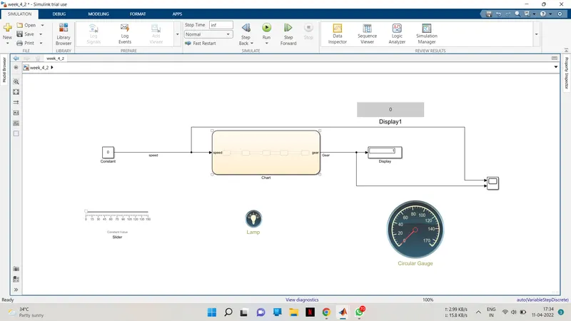
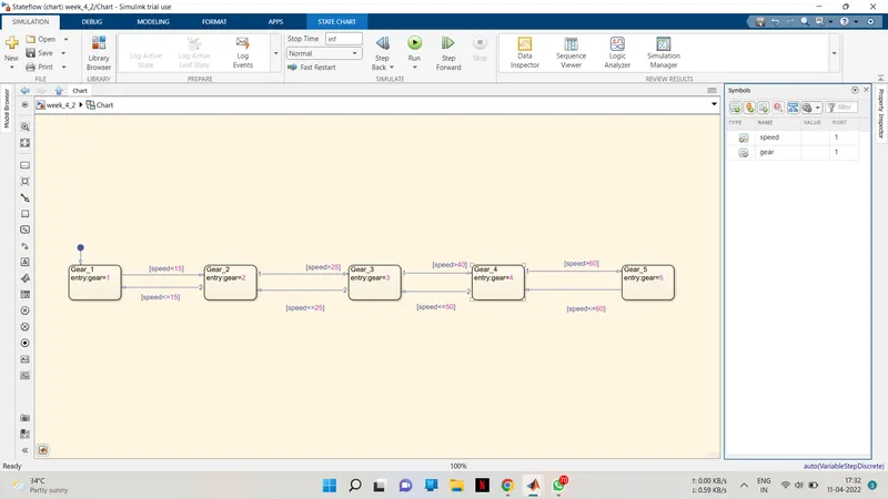
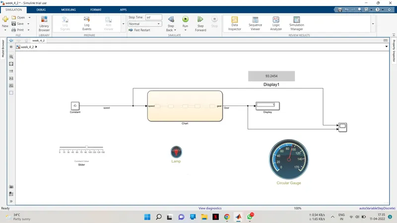
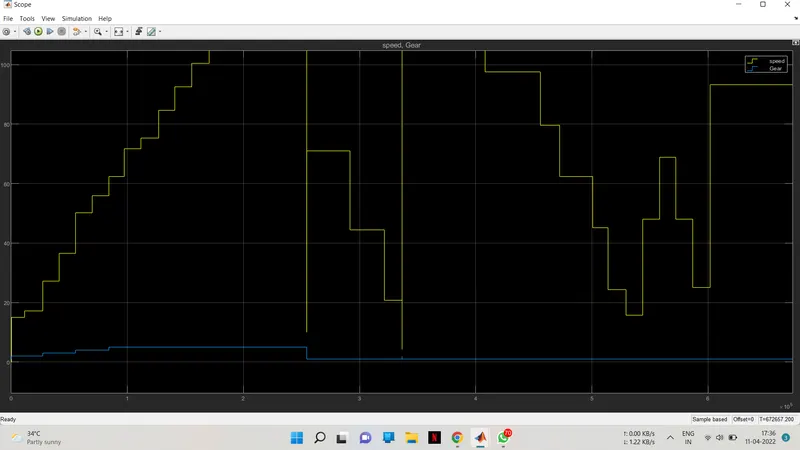
- Here we have used ‘CHART BLOCK’ to define the gear shift logic for the conditions given above.
- First, we have defined fives states namely ‘Gear 1’, ‘Gear 2’, ‘Gear 3’, ‘Gear 4’, ‘Gear 5’.
- When the speed is greater than 25 the state will go to Gear 3 state and stay there till speed is less than equal to 40. Speed is given by slider which is displayed by custom guage which acts as speedometer. The gear position 3 will be displayed by gear display block.
- When the speed is greater than 40 the state will go to Gear 4 state and stay there till speed is less than equal to 61. Speed is given by slider which is displayed by custom guage which acts as speedometer. The gear position 4 will be displayed by gear display block.
- When the speed is greater than 61 the state will go to Gear 5 state and stay there until the speed falls back to 61. Speed is given by slider which is displayed by custom guage which acts as speedometer. The gear position 5 will be displayed by gear display block
- Now to give speed as input we have used a ‘Signal Builder Block’, where we have defined the defined the different speeds.