Week - 4
- Implement control logic of a “washing machine” using Stateflow as per given sequence:
- If the power supply is available, the system gets activated
- If the Water supply is not available, stop the process & indicate through LED
- Soaking time should be 200s followed by Washing time of 100s.
- Then rinsing happens for next 20s & dryer runs for 50s.
initially we will do the chart creation for Washing machine
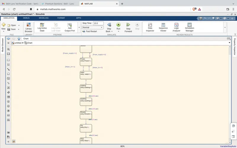
We will configure input output signals from Symbol pane.
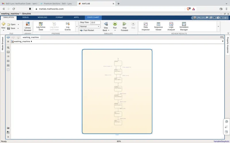
1--> Power_supply is not available so machine reamains turned "OFF".So, no output visisble on display and LED's.
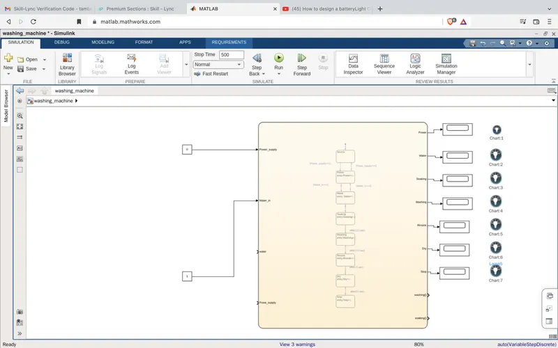
2--> Power supply=1 is available and water supply=0 is not available. Machine reamains turned "OFF"and we can see only the Power_supply LED is glowing as input is available .
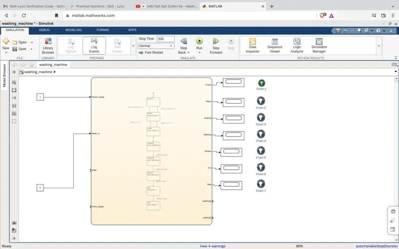
3--> Power_supply=1 is available and water supply(Water_in=1) also available.Then machien will turn "ON "and we can see the ouput on display and glowing LED's with respect to time.
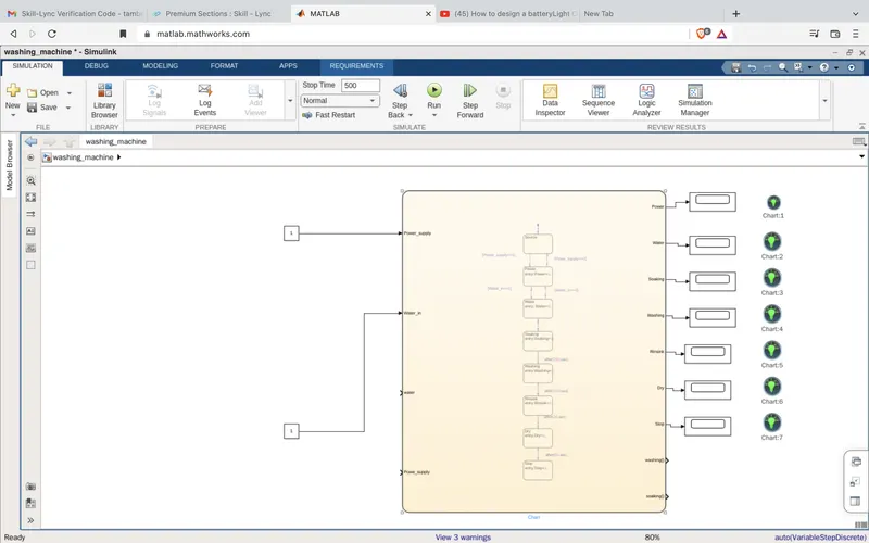
Process time defined as follows :
1.Soaking time = 200s
2.Washing time =100s.(200-300s)
3.rinsing time =20s(300-320sec)
4. drying time= 50s(320-370sec)
After all the processes completed Stop LED will turn "ON"
2. Make a Simulink chart for the “Gear shift” logic as per below conditions:
initially we will do the chart creation for Gear shift mechanism as follows :
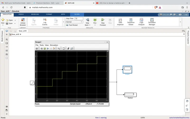
Speed Range(kmph) Gear
0 to 15 1
16 to 25 2
26 to 40 3
41 to 60 4
Above 61 5
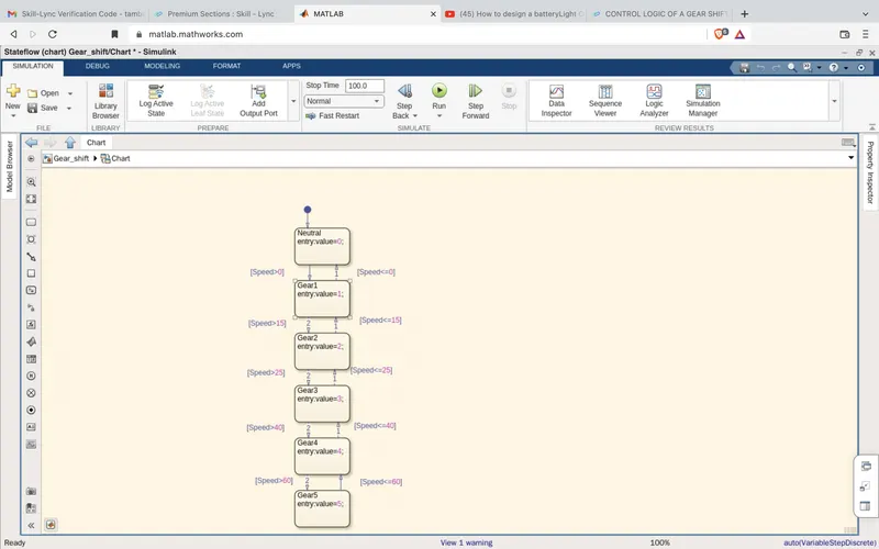
Configure input and output signals to the chart :
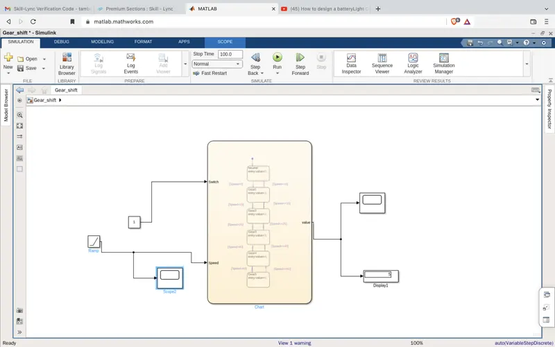
NOTE: we are using Ramp input signal to vary input speed value with respect to time.
Input spped varing during simulation running :
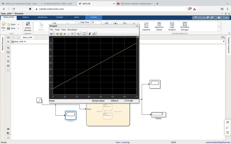
Check Output as gear possition changing with resect to input spped value changing :
speed varies from 0-70kmph so final result we are getting gear value=5 as speed value is > 61Kmph
Lets check for speed signal vary slowly :
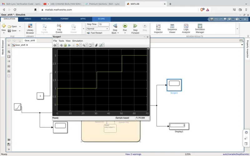
Input Spped varies from 0-35 so we will get gear shift to 3 as speed value in between (26 to 40Kmph)