Project
Aim: To Prepare a technical report explaining the model properties & comments on the resultsof BAJA-All-Terrain-Vehicle-Model
objective to use the modeling :
This submission contains a set of models created with Simulink, Simscape, and Simscape Driveline.
More specifically, the file contained includes BAJA ATV model with Continuously Variable Transmission(CVT).
These models show how to build an ATV with CVT which is mostly used in BAJA competitions. Simscape and Simscape Driveline have been used to complete the system. The engine data used in the model is provided as an image which shows the Engine Speed (RPM) Vs Torque curve.
Model1:
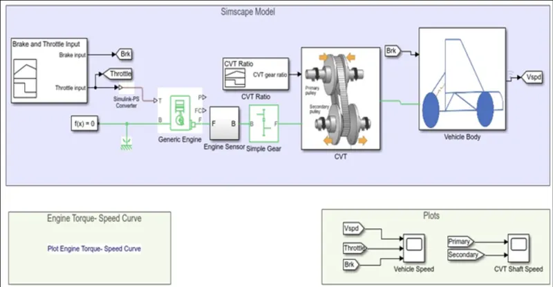
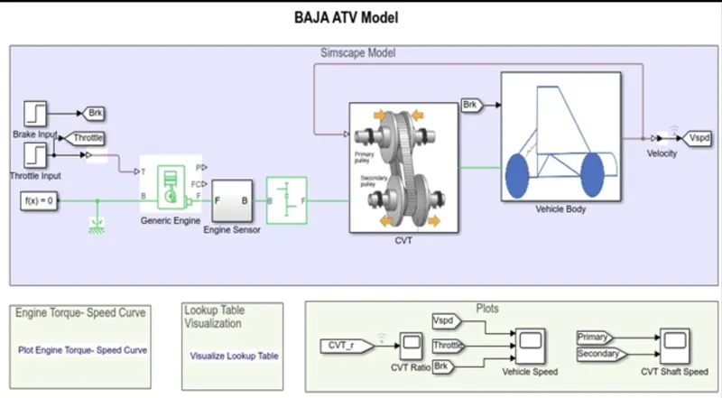
Simulink model for BAJA ATV with CVT
Components used for simulink model :
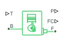
1.Generic Engine :The Generic Engine block represents a general internal combustion engine. This block is a suitable generic engine for spark-ignition and diesel. Speed-power and speed-torque parameterizations are provided. A throttle physical signal input specifies the normalized engine torque. Optional dynamic parameters include crankshaft inertia and response time lag. A physical signal port outputs the engine fuel consumption rate based on the fuel consumption model that you choose. Optional speed and redline controllers prevent engine stall and enable cruise control.
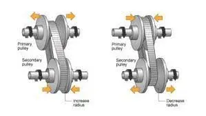
2.CVT:Unlike traditional automatic transmissions, continuously variable transmissions don't have a gearbox with a set number of gears, which means they don't have interlocking toothed wheels. The most common type of CVT operates on an ingenious pulley system that allows an infinite variability between highest and lowest gears with no discrete steps or shifts.
Features
- Constant, stepless acceleration from a complete stop to cruising speed
- Works to keep the car in its optimum power range regardless of how fast the car is traveling
- Responds better to changing conditions, such as changes in throttle and speed
- Less power loss in a CVT than a typical automatic transmission
- Better control of a gasoline engine's speed range
- Can incorporate automated versions of mechanical clutches
Benefits
- Eliminates "shift shock" -- makes for a smoother ride
- Improved fuel efficiency
- Eliminates gear hunting as a car decelerates, especially going up a hill
- Better acceleration
- Better control of emissions
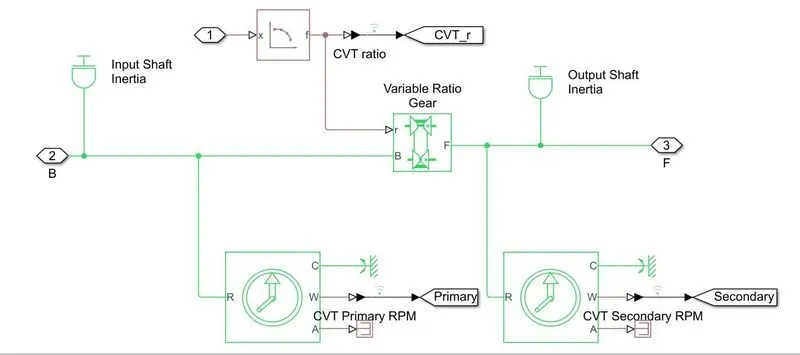
a) Variable_Ratio_Gear:he Variable Ratio Transmission block represents a gearbox that dynamically transfers motion and torque between the two connected driveshaft axes, the base and the follower.
It is used to define variable Gear ratio according to model requirements.

b) Input /Output Inertia:
The Inertia block represents an ideal mechanical translational inertia
it represents the primary and secondary pully drive in a CVT block.

c) RPM Sensor:
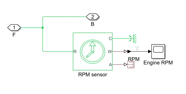
To check the RPM value on primary and secondary pully.
3.simple Gear:
This block is used to connect engine and the CVT which has fixed gear ratio.

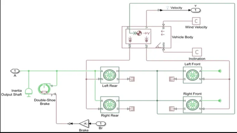
4.vehicle Body
This system is represnts the whole vehicle body to which the input from engine trought the gear ratio has been feeded.Also brake signal is provided to this block from signal builder 2.
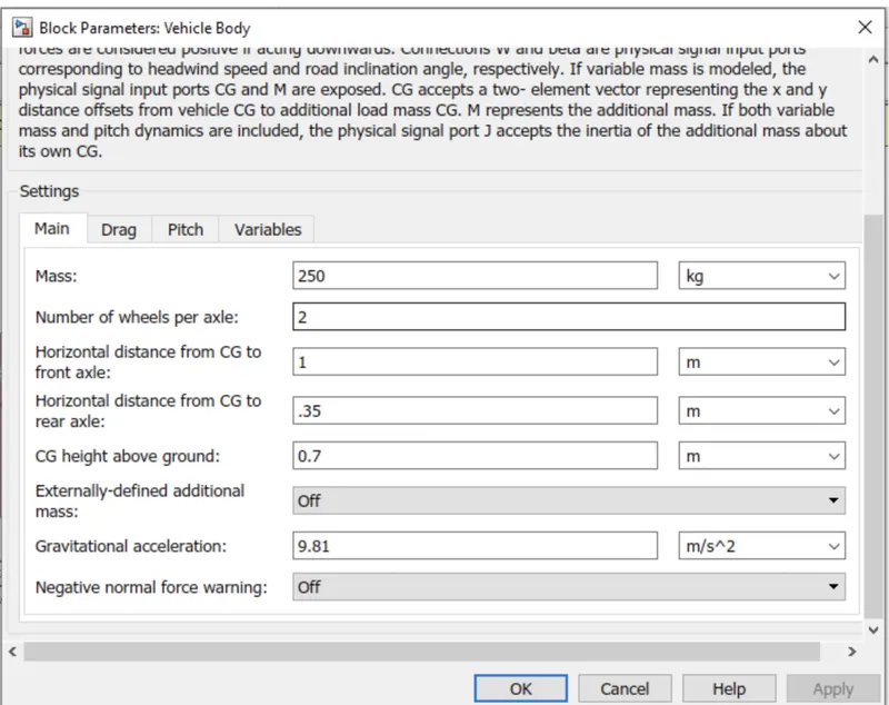
Vehicle body input parameter configuration :
5.Signal Builder 1:
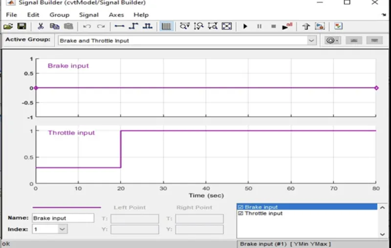
This block is used to provide throttel input to the Engine and brake input to the vehicle body subsystem.
6. Signal Builder 2:
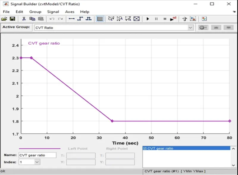
This block is used to provide input to CVT subsystem.This will provide variable gear ratio during the simulation period.
Output of first Model:
The brake signal is converted to physiscal signal by using simulink -PS converter.That physiscal signal is given to vehice tires trough shoe padel block.
Lets check velocity of vehicle changing according to throttle signal change provided to Vehicle:
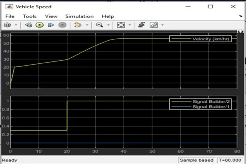
we can see from the vehicle output graph :
1.velocity instantly increases to 20 kmph for a throttle value of 0.3.
2.Once the throttle value is increased to 1 vehicle gain its maximum speed around 55kmph within 20s.
CVT shaft RPM check:
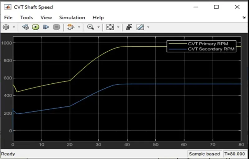
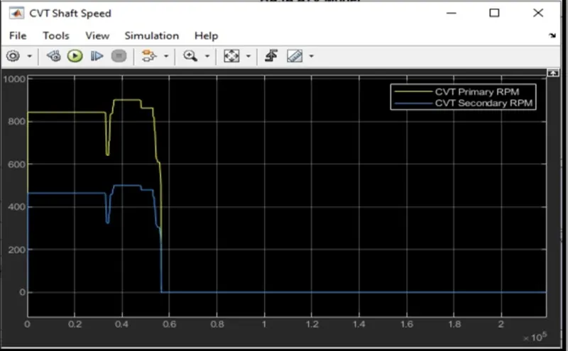
We can see the variation in angular velocities of input and output shafts of variable gear transmission system.
Type1
Case2:
Simulink Model for BAJA ATV with CVT using dashboard:
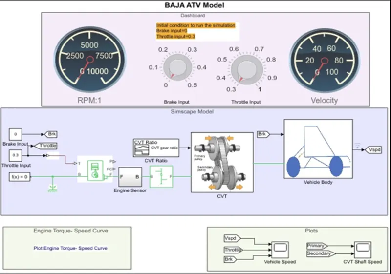
For this case we have two knobs to vary thrrottle and brake.We are not having signal builder as input to the model.
By varing the throttle and brake lets check the output on scope :
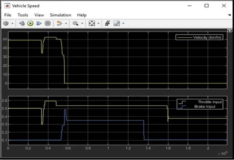
Here we can see while the brake input value=0 and the throttle is provided.The velocity is changing drastically to around 50kmph. As the brake input is given upto 0.5 the velocity will decrease till o kmph.
CVT shaft Output :
Type 2:
Case 1:Simulink model for BAJA ATV with CVT using LOOKUP Table:
CVT shaft subsystem:
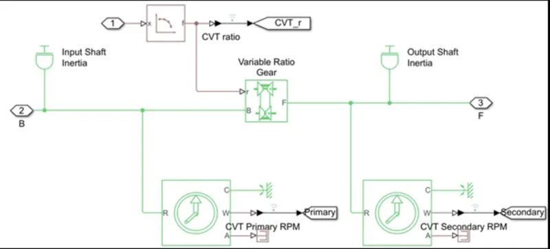
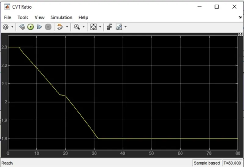
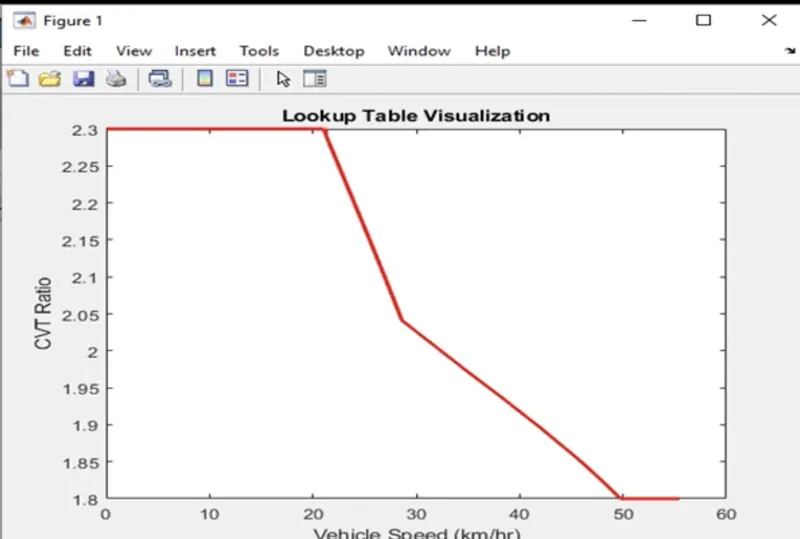
Here we can observe that the variable transmission ratio is not provided by signal builder.Instead of that we are providing transmission ratio trough the lookup table.
Here another thing we need to focus on the Brake and the throttle are same as previous one.So, the change in velocity is almost same to that one.
INPUTS Provided:
CVT Gear ratio:
Lookup table :
CHECK Output for type 2 case1:
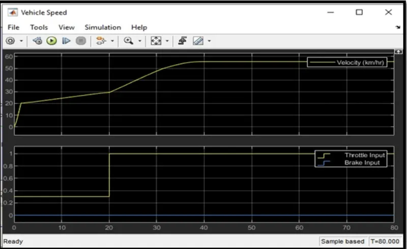
Velocity change with respect to input values of Brake and throttle:
Result:
we can see from the vehicle output graph :
1.velocity instantly increases to 20 kmph for a throttle value of 0.3.
2.Once the throttle value is increased to 1 vehicle gain its maximum speed around 55kmph within 20s.
CVT Gear output:
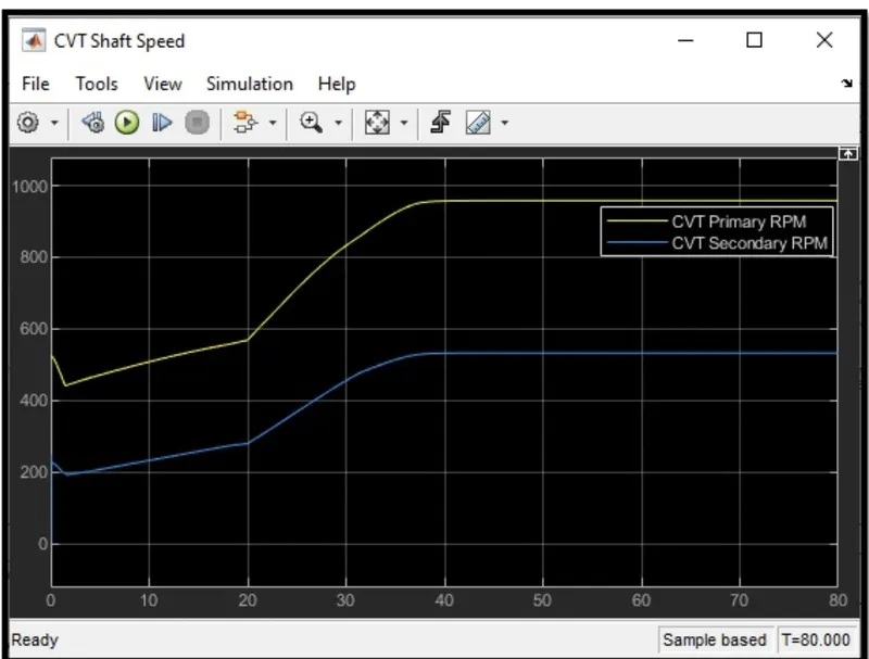
Rsult :
We can see the variation in angular velocities (rpm)of input and output shafts of variable gear transmission system.
Type2:
Case2 :Simulink model for BAJA ATV with CVT using LOOKUP Table and Dashboard:
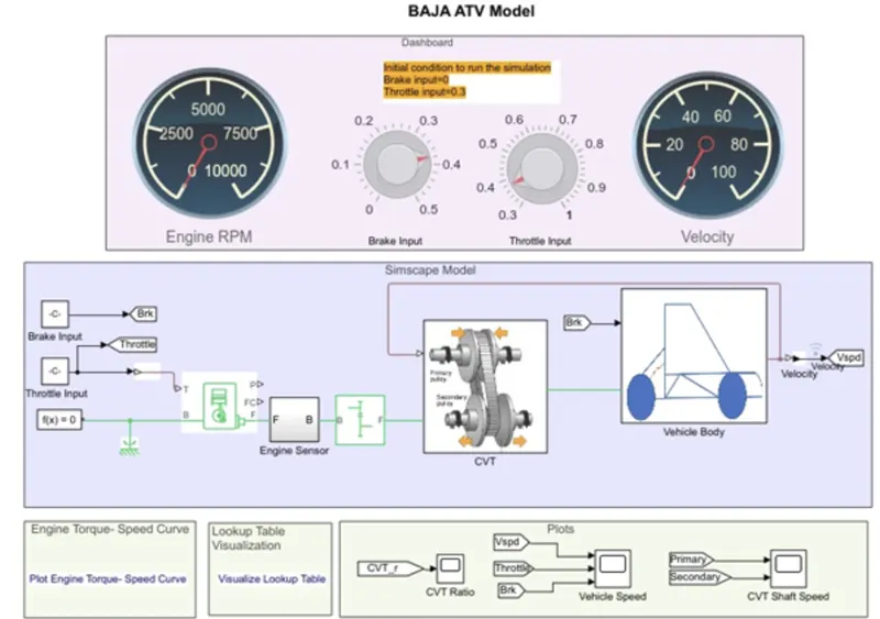
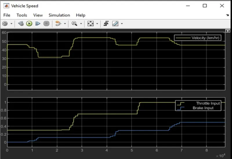
Result: Vehicle velocity is chganging according to the throtte and brake inputes provide by using the dashboard knobs.
CVT Shaft Output:
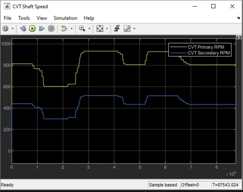
Here we can see the primary and secondary shaft angular velocity(RPM)according to variation in input parameters .
Conclusion:
we have analysed all the system and observed the differnet type of behaviours of them.
1.if we change valus from signal builder the output is predefined(befoere the simulation run)
2. By using the dashboard we can change the input parameters during the simulation time.
3.By using Lookup table we are not able to vary brake and throttle inputs to the system.