Week - 4
there are two concepts that requires the state flow model representation
WASHING MACHINE UNIT:
1.we are to model a washing machine that performs four fuctions like soaking, washing, drying and rinsing.
the functions are to be performed in a timely basis.
the requirements of the design is as follows:
1.If the power supply is available, the system gets activated.
2.If the Water supply is not available, stop the process & indicate through LED.
3.Soaking time should be 200s followed by Washing time of 100s.
4.Then rinsing happens for next 20s & dryer runs for 50s.
5.After all the processes have completed turn on the finished LED.
making of the model:
1.we are first defining the source of power and water with the help of slider switch, it works on the values of 1 and 0.
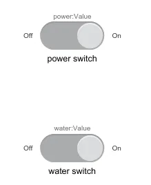
2.the switch is connected to the constant value block which defines the input from it.
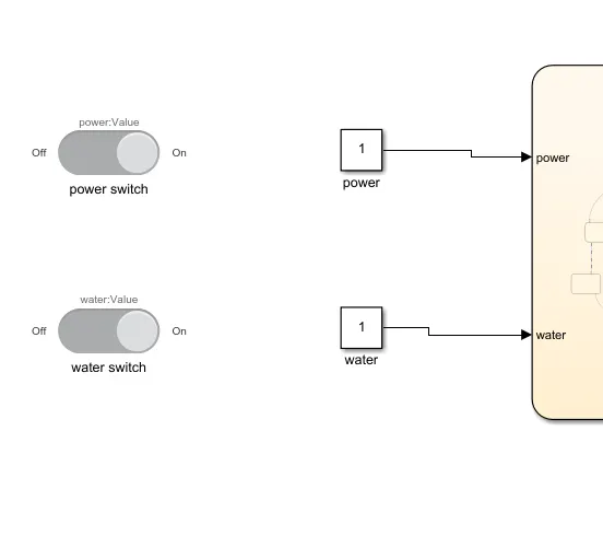
3.the water and power are made as a source and are ready to be given as input to the washing machine system.
4.to make the system for washing machine we are using the stateflow chart block.
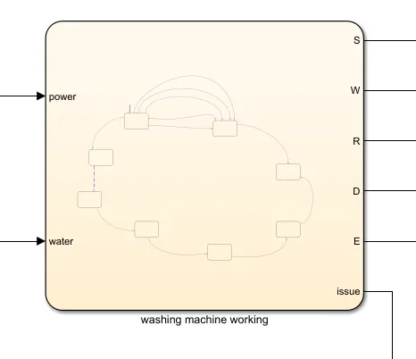
this shows the chart block which is helpful in making the washing machine simulation.
the machine function is stated within it in the above diagram, we can see the fuctions within the above chart below
5.the chart block contains many sub charts that help with the formation of a code.
6.the chart option within the chart block helps with containing the values of the function.
7.we drag and drop the chart in the chart block and it forms the source
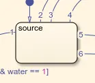
8.if we drag it again it forms a basic block, in these basic blocks we are to state the input values so the function of the washing machine can be coded
9.the first inputs that is the power and the water are made possible from the outside source. if the water input is 1 then the water is available. this is same when considering the power too.
10.if the water and power is present then the inputs are then moved to the next block which leads to function code 'start'
11.if the values are not given in then they are branched into another chart block called 'error'.
12.the error block then leads to end block, in the error block a lamp is made to flash, that states the error in the input.
13.if every input value satisfies the condition that is power and water is 1 then it flows on to the other states defined.
14.the power and water then reaches the ''SOAKING'' block where the soaking happens for about 200 sec
15.after it reaches the washing where it happens for the next 100 sec.
16.then it flows to the rinsing and drying in a time gap of 20 and 50 seconds.
17.finally it reaches the end.
18.the soaking, washing, rinsing, and the drying phases are connected in series and the all contains an entry and an exit value. these phases are connected to a lamp and display for understanding.
19.the entry value is made as 1 and exit 2. exit is made 2 coz the flows are to be stated with help of lamps too. if the exit is to be stated 0 then the lamp will be glowing even when ther is input error.
20.if the entry is happening then the lamps glow red, once ending a phase the lamp glows green.
21.finally once after completing the functions the process ends and outputs are stated in the display and the lamp.
22.before running the code the inputs and outputs are stated with the help of signal port.
the outputs are stted in the display and the lamp as follows
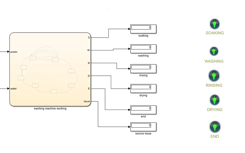
in the above we can see that the four main process are done since we can see the display as 2 and the lamps are all green once after completing the entire process.
the end is stated as 0 and 1, where 0 gives the successful ending. source issue is 0 since there is no issue in the above, if there is error it shows 2.
main stateflow block code for good power and water source:
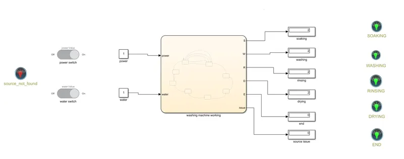
the power is on and the water is on too.
we can see the outputs of the flow inside the washing machine.
the display shows 2 for all main process and the lamp is green.
source not found lamp is in red as there is no error, if error in the function then it glows blue.
main stateflow block code for good power and bad water source:
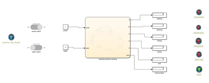
we can see the source not found lamp in blue, so there is error and the displays are all 0 in main function and the source issue is shown 2. there is error in this system.
state flow chart (washing machine function):
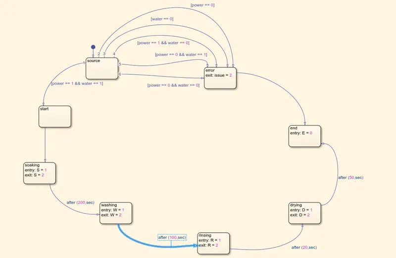
the source is where things flow from. satisfying the conditions the flow of power and water gives the desired output value we require.
................................................................................................................................................................................................................................................................................................................................................................
SIMULINK FOR GEAR SHIFT:
we are to make a simulink model for the gear shift logic.
we are going to use many blocks we used in the previous logic we seen.
1.we are to use two input sources they are power and the throttle. the power is provided with the help of switch and the throttle input with the help of the slider block.
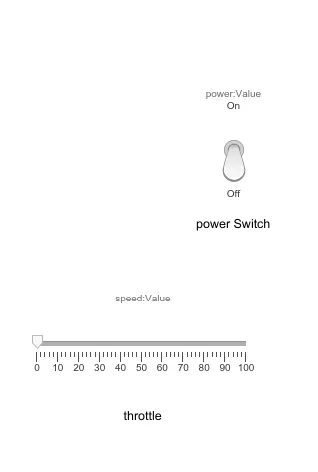
switch works with the help of 1 and 0.
slider bar helps in achieving varying speed when the system runs.
2.these two are then attached to constant block to provide values. the constant block varies according to the switch and the slider.
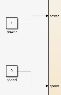
3.the values are then sent into the stateflow chart which represents the working of the gear shift.
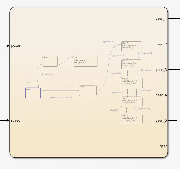
4.the chart block contains many sub charts that help with the formation of a code.
5.the chart option within the chart block helps with containing the values of the function.
6.we drag and drop the chart in the chart block and it forms the source
7.if we drag it again it forms a basic block, in these basic blocks we are to state the input values so the function of the gear shifter can be coded
8.the source block takes in the input values of the power switch and the slider and directs it according to the condition stated.
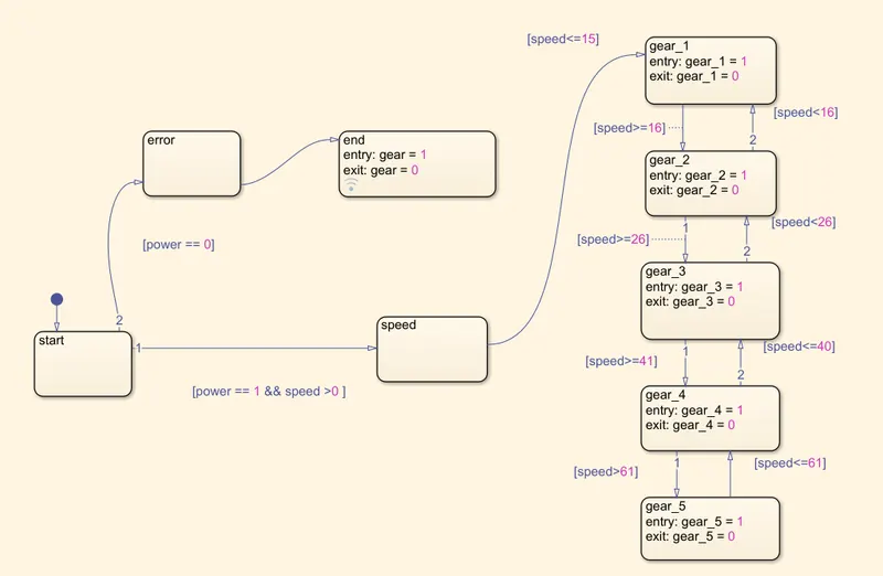
9.the inputs if the power is 1 and the speeod is greater than 0 then it pass to the speed chart. if the power is 0 then it pass to the error chart and then to the end.
10.the end gives the output 1 if there is an error, it is connected to the gear display output stating no power.
11.after once the varying speed reaches the speed chat, it is sent into five different chat block according to the speed input.
12.when the speed is less than or equal to 15 then the speed is taken in the gear_1. the speed when reaches 16 and above but below than 25 then it is made to represent the gear_2.speed above 25 and below 40 is then sent to gear_3, speed>40 and <60 is taken to gear_4, speed above 61 is taken to gear_5.
13.entry is 1 and exit is 0 in all the gear blocks.1 shows the working of that gear.
14.gear block is made in contact with the display and the lamp block.
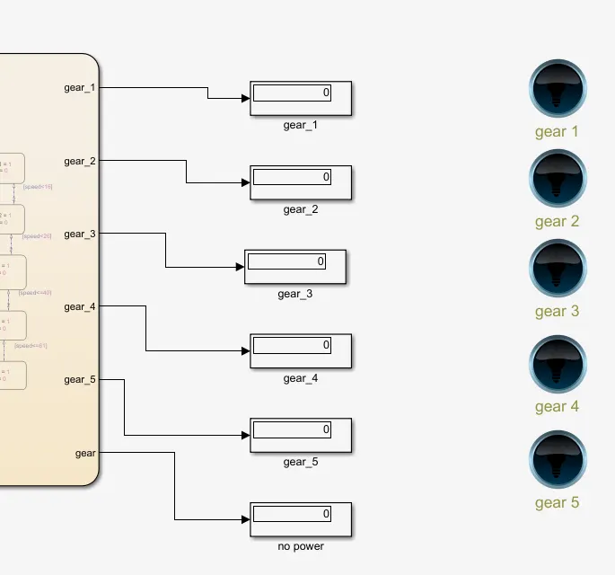
15.the output that is the working of the gear in the system is understood well from the lamp glow.
16.when first gear is engaged then first gear lamp is glown and so on.
main code simulink block that shows when power is off:
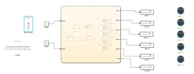
it shows the power is off and the output for gear shows 1 in no power display. there is no power in the system, hence the gear shifter will not operate.
main code simulink block that shows when power is on:
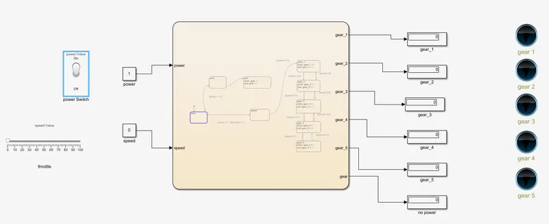
the power is made on and the system is ready to accept varying inputs from throttle.
gear_1:
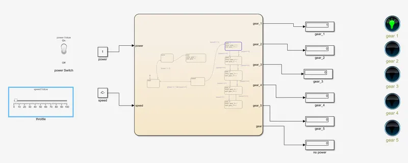
here the throttle is moved from 0 to 5, since it is present below 15, gear_1 is engaged which gives display output 1 and gear 1 lamp glows.
gear_2:
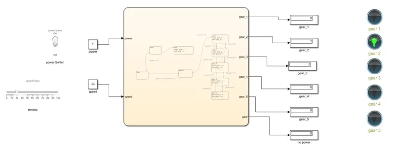
here the throttle is moved from 0 to 20, since it is present above 15 and below 25, gear_2 is engaged which gives display output 1 and gear 2 lamp glows.
gear_3:
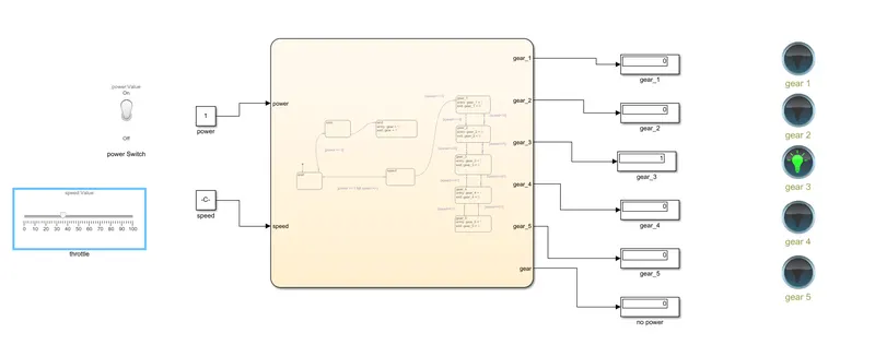
here the throttle is moved from 0 to 37, since it is present above 26 and below 40, gear_3 is engaged which gives display output 1 and gear 3 lamp glows.
gear_4:
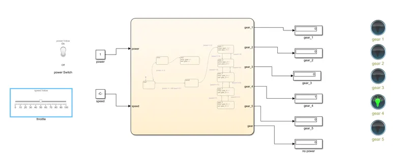
here the throttle is moved from 0 to 50, since it is present above 40 and below 60, gear_4 is engaged which gives display output 1 and gear 4 lamp glows.
gear_5:
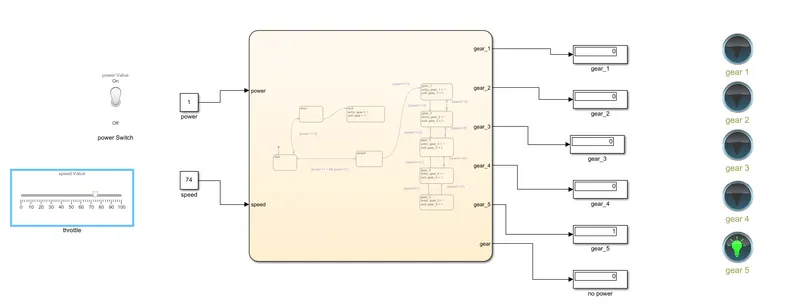
here the throttle is moved from 0 to 73, since it is present above 61, gear_5 is engaged which gives display output 1 and gear 5 lamp glows.
the stateflow chart for the gear shifter:
conclusion:
the given washing machine model and the gear shifter model has been successfully done with simulink and stateflow chart.
and they are made to act according to the conditions stated.