Week - 4
- Implement control logic of a “washing machine” using Stateflow as per given sequence
-
Introduction:
Objective of the challenge is to replicate the process occur in a wasing machine. Soak,wash, rinse, dry. To perform this we are using stateflow chart.
Methodology:
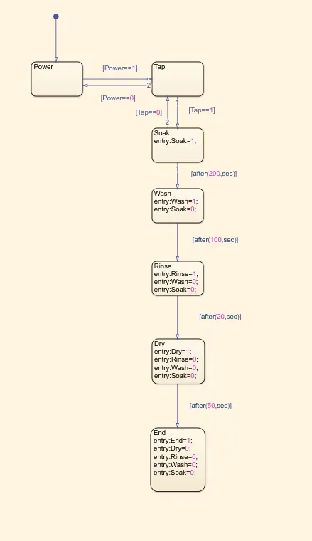
- Initially when the power is On, the condition should me moved to water supply. [power==1]
- In the second state, we are giving the condition that machine should not start the process without water supply eventhough power is on [Tap==1](denoted as tap) which means tap is on open state. If we forgot to open the tap process wont move to next state.
- When tap is open, the Soak process get started. Soaking will be occur for 200 seconds after that washing process gets starts. This can be conditioned as [after(200,sec)].
- The next process starts after 100 second of washing.
- Rinse is the next process after washing.It can be conditioned as [after(100,sec)].
- Likewise Rinse for 20 seconds and dry for 50 seconds
- After the comnpletion of secquence of process we assigned the program will get ends.
-
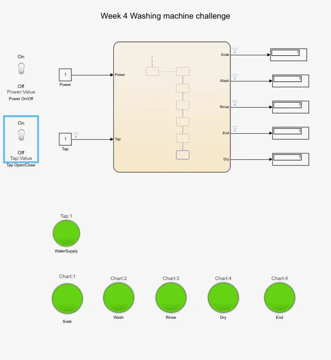
- Here, i used toggle switch to control power and water supply.Both are connected to resprective constant blocks.
- Condition from constant blocks will taken as input data by the states.
- Each output datas from stateflow are connected to correcponding constant blocks and lamp(LED indicator)
Outputs:
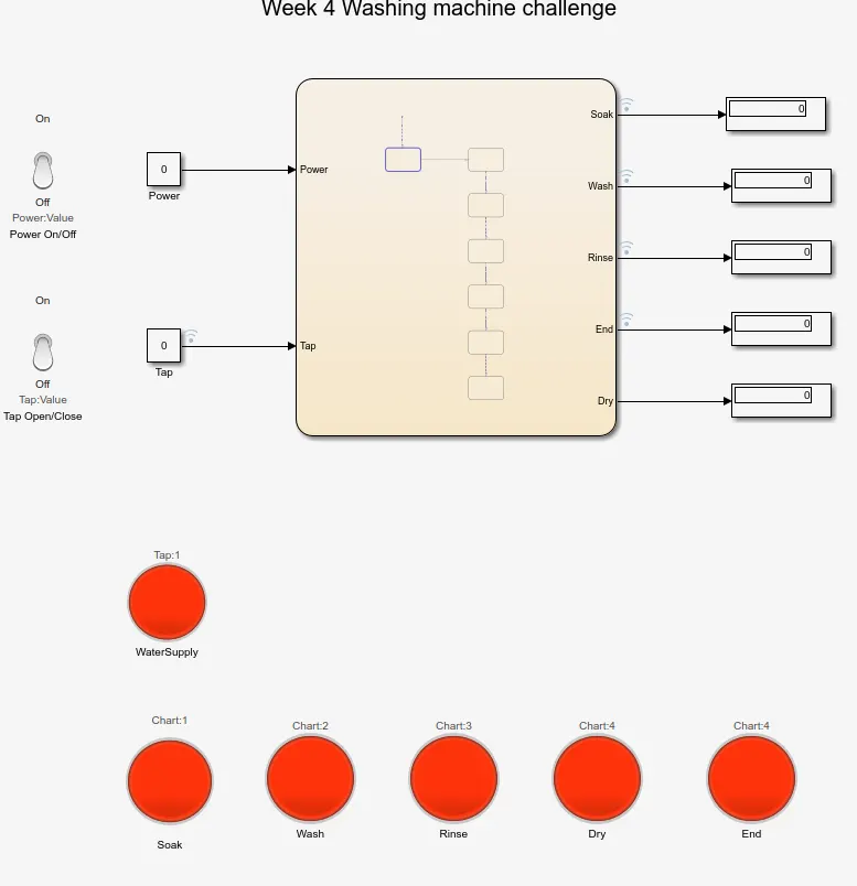
When Power is on and Tap is close
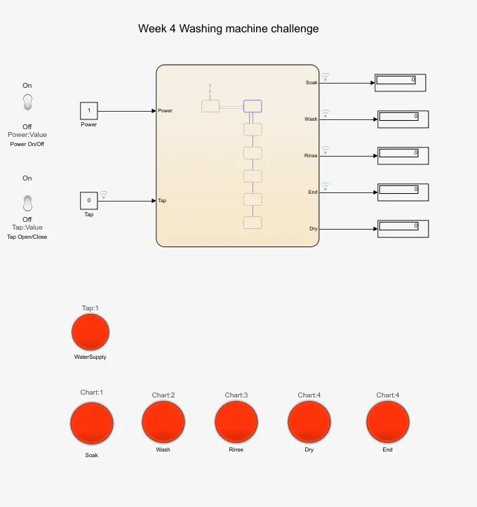
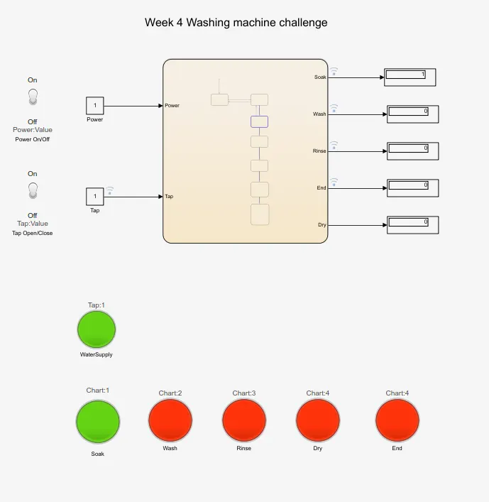
When the tap opened all the process gets start by sequence. Initially soaking for 200 seconds
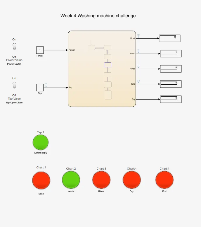
After soaking rinse get started.
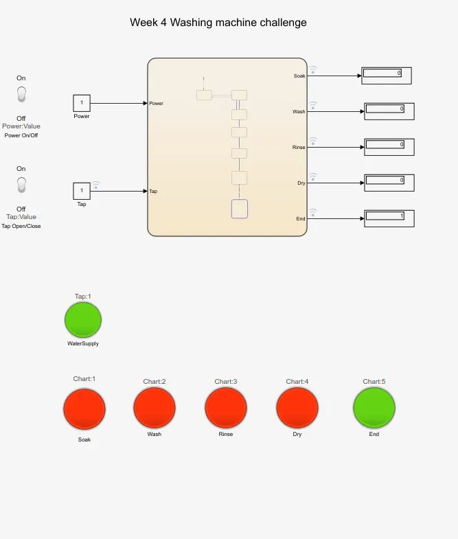
When all the process completed, End light indicator get activated.
2.Make a Simulink chart for the “Gear shift” logic as per below conditions:
Speed Range(kmph) Gear
0 to 15 1
16 to 25 2
26 to 40 3
41 to 60 4
Above 61 5
Introduction:
Objective of the challenge is to give the gear number according to the speed the vehicle travels. To perform this action we using “stateflow” to make the conditions.
Methodology:
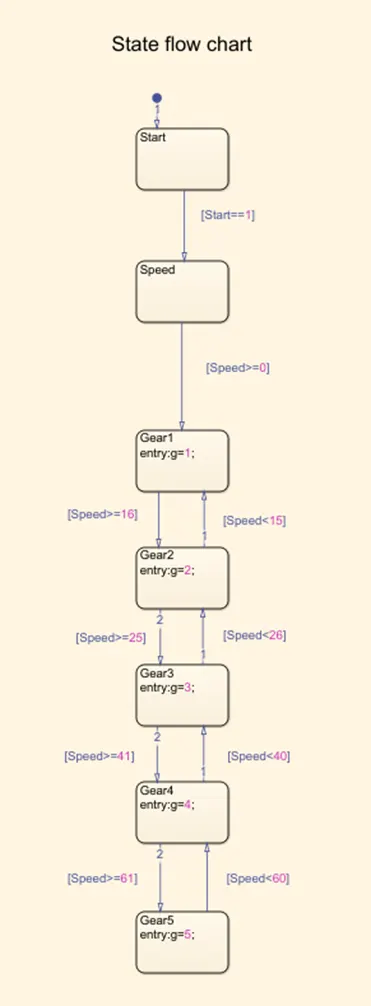
- Initially condition is that, engine as to start(on/off). This can be given by the constant block on==1, off==0. I used toggle switch to represent engine on/off.
- Then we are manually giving the speed it travels, it can also give by constant block which connected to a slider. So, we can adjust the value easily while the program runs.
- In stateflow, when the engine get started, it moves on to the next condition speed.Whatever the input we give it will passed to the sequence states arranged.
- First gear speed limit is 0-15,so we create the as gear one (g=1) it will be activated when the speed limit is 0-15. The condition is between [speed>=0] & [speed<15].
- When ever the input speed lies btw 0-15, this condition gets activated and gives output data as gear 1.
- Likewise for gear position 2,3,4,5 are mentioned.
- Gear position 2 is between [speed>=16] & [speed<25].
- Gear position 3 is between [speed>=26] & [speed<40].
- Gear position 4 is between [speed>=41] & [speed<60].
- Gear position 5 is between [speed>=61]
- To change the speed while the program runs, make the time period as infinity(inf)
- Connect the gear output data to constant block or half gauge analog meter, etc to view
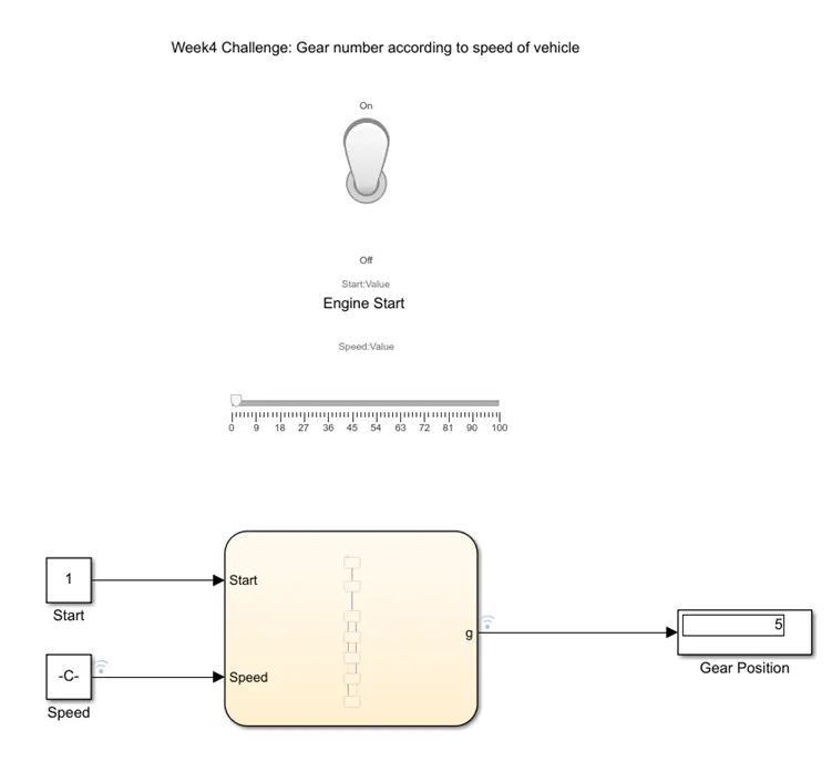
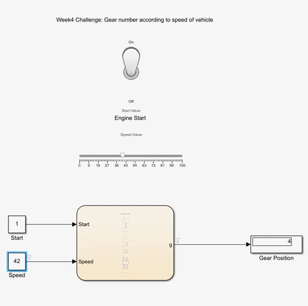
Output:
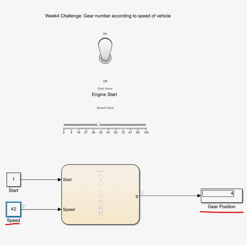
Thus, output of both the challenge are achinved.
Here, is my files
https://drive.google.com/drive/folders/1zkwwVmxpwrT1wVs_csLPW3NRBr1rbVu2?usp=sharing