Project
Objective:
To prepare a technical report on Baja AVT vehicle models. Explaining the model properties & comments on the results.
Introduction:
A continuously variable transmission (CVT) is an automatic transmission that can change seamlessly through a continuous range of gear ratios. This contrasts with other transmissions that provide a limited number of gear ratios in fixed steps. The flexibility of a CVT with suitable control may allow the engine to operate at a constant RPM while the vehicle moves at varying speeds.
CVTs are used in automobiles, tractors, motor scooters, snowmobiles, bicycles and earthmoving equipment.
The most common type of CVT uses two pulleys connected by a belt or chain; however, several other designs have also been used at times.
To see how a CVT works, you need to understand a manual and a traditional automatic Transmission. A manual has a set number of gears and the driver determines what gear ratio he needs. An automatic also has a set number of gears but uses a hydraulic system that responds to the pressure created by the conditions to determine the gear required without operator input.
A CVT is similar to an automatic in that it doesn’t use any input from the driver, but that’s where the similarities end. A CVT has no gears. Instead, it has two pulleys. One pulley is connected to the engine and the other to the wheels. A flexible belt connects the two pulleys.
The width of the pulley’s changes depending on how much power the vehicle needs. As one pulley gets bigger, the other gets smaller. Since neither the pulleys nor the belt is fixed, they can provide an infinite number of gear ratios in contrast to the automatic with a fixed number of gears.
Advantages Of CVT Over Automatic Transmissions
Outstanding fuel efficiency is a major advantage for your Bloomfield and Troy commutes. CVTs are always adjusting, so they keep engine RPMs low and consistent, avoiding the high engine speeds that suck down gasoline.
CVTs also have lower production costs because they have fewer moving parts than traditional automatics. This is another appealing factor to car manufacturers, and thus to car buyers as well.
CVTs deliver a smooth ride because the transmission doesn’t have to constantly switch gears.
Disadvantages Of CVT Over Automatic Transmissions
You may feel a delay when you step on the accelerator. That’s because, compared to a regular automatic transmission, there’s a slight pause as the CVT band adjusts.
CVTs can be hard to get used to because they just don’t feel the same way a traditional automatic doe. The engine sound is monotonous, and you don’t feel a connection with the car like you do when you can tell a gear has shifted.
In spite of the low initial costs of a CVT, repairs can be more expensive because the parts are more costly to replace. And because technicians need special training, it may be harder to find someone that can make the repair. This has become less of an issue as CVTs have become more common.
By using Simulink, Simscape, and Simscape Driveline this model is built to understand the design consideration of a Baja ATV model which has the CVT as gear transmission mechanism. Here, we can learn how to build an ATV with CVT which is mostly used in BAJA Competitions.
Model Explanation:
MATLAB provides us a Simulink model which is used by students and professional who participate in Baja vehicle competition. In which one can build a perfect condition vehicle based on studies. Now, we are going to look at two different models. Both are used to study Baja ATV those are
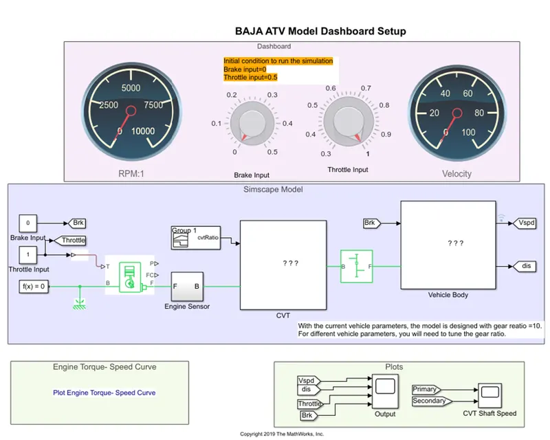
CVT model with dashboard setup
This model will give real time report by turning the knob. This model will run for infinite time, during the stimulation we can rotate the knobs the final plot will be seen after we stop the stimulation. Here we can read velocity at each state during our manual controlled throttle and brake.
Disadvantage I felt in this model
- In real time, adjustment between brake and throttle will be simultaneous. Here, at a time we can control only either of the parameter. If I apply brake, the throttle remains same until I the change it manually. But when we change the brake at constant throttle, we can see the RPM also change accordingly which give the velocity of the vehicle at that time.
- Program get stop when the brake applied fully. The throttle and brake value alone get recorded, meanwhile the velocity goes to 0 and remains same till the end of the program.
Here we will get higher RPM when the throttle is value and brake at zero.
CVT model without dashboard setup
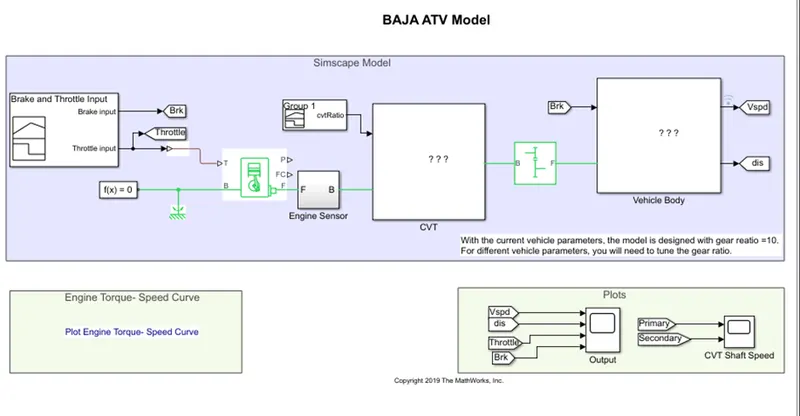
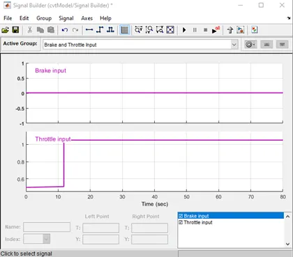
Here, step signal is used as an input for brake and throttle. Output engine RPM is got from these inputs. The gear ratio applied from the lookup table. Real condition of gear ratio as per speed.
We can adjust the run time speed and corresponding brake, throttle value. RPM and velocity will be the resultant data’s.
Factors considered:
- Powertrain – General SI engine is used
- Gear transmission – CVT
- Vehicle body factors (|Body weight, tyre dimensions, Body dynamics and dimensions, etc)
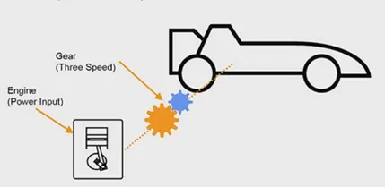
Factors considered:
- Powertrain – General SI engine is used
- Gear transmission – CVT
- Vehicle body factors (|Body weight, tyre dimensions, Body dynamics and dimensions, etc)
Powertrain factors:
This model is power by SI engine. In MATLAB we have Generic engine SI block, which can be used here.
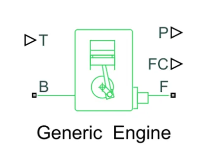
This is the engine block, in which we can give certain inputs to perform the action.
- Tabulated driven Speed and Torque data
- Engine inertia – 5 kg*m^2
- Initial velocity -1600 rpm
- Speed threshold – 100 rpm
- Amount of fuel is being consumed & speed control (in our model we don’t use it)
Engine block have two mechanical connections and two physical signal output ports
Port B – Engine block which connect to rotational mechanical reference and solver configuration.
Port F – Engine crankshaft which connects to RPM sensor and to Variable ratio gear
Port P – Engine power
Port FC – Fuel consumption
Gear transmission – CVT
To represent CVT we use Represents a variable ratio gearbox implemented by mechanical belt. The physical signal input r defines the ratio of input to output angular shaft velocities.
Connections B (base) and F (follower) are mechanical rotational conserving ports. Data from engine block is taken as the input and signal builder.
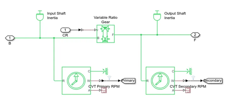
The Variable Ratio Transmission block represents a gearbox that dynamically transfers motion and torque between the two connected driveshaft axes, base and follower. Here the B Port is the input RPM which is connected from engine crankshaft. F port is the output which falls to the simple gear to represent the change in ratio alone. The output ratio will be the input the tyres (vehicle body).
Vehicle body factors
Baja ATV physical dimensions are mentioned here,which is the most important thing while designing the vehicle.
We can determine perfect value for better performance of vehicle. Some factors given below
- To know variation based on body weight.
- Results based on Centre of gravity
- Tyre model, basically with tyre radius and load act each tyre.
- Braking system
- Vehicle suspensions system, etc
Baja vehicle dimensions:
Mass = 250 kg
No. of wheel per axle = 2
Distance of front axle from CG = 1m
Distance of rear axle from CG = 0.35m
CG height above ground = 0.7m
Frontal area = 0.735482 m^2
Drag coefficient = 1.92
Air density = 1.18 kg/m^3
Input Parameters:
- Brake – Constant block
- Throttle – Constant block
- Speed vector
- Torque vector
- Input shaft Inertia
- Output shaft Inertia
- Break
- Double shoe brake
- Tire
- Wind velocity
- Road inclination angle
Output Parameters:
- Engine RPM
- Velocity
- Angular displacement
Required blocks:
- Solver
- Mechanical reference
- Generic SI engine
- PMC Port (Physical modelling connection)
- Rotational motion sensor
- PS lookup table
- Variable ratio transmission -CVT representation
- Simple gear ratio
- Goto
- PS terminator
- Vehicle body
Results
Results from dashboard model
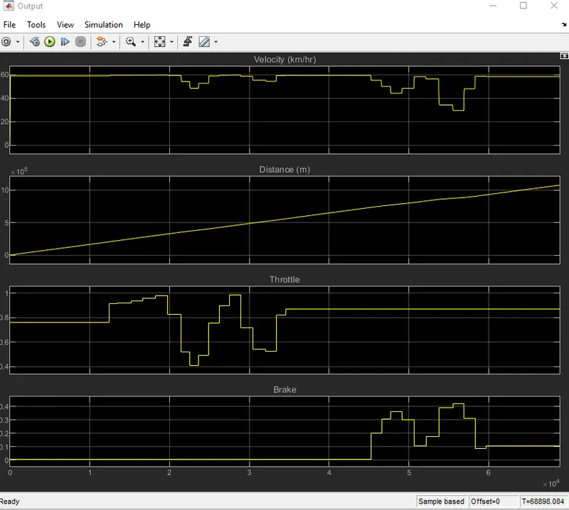
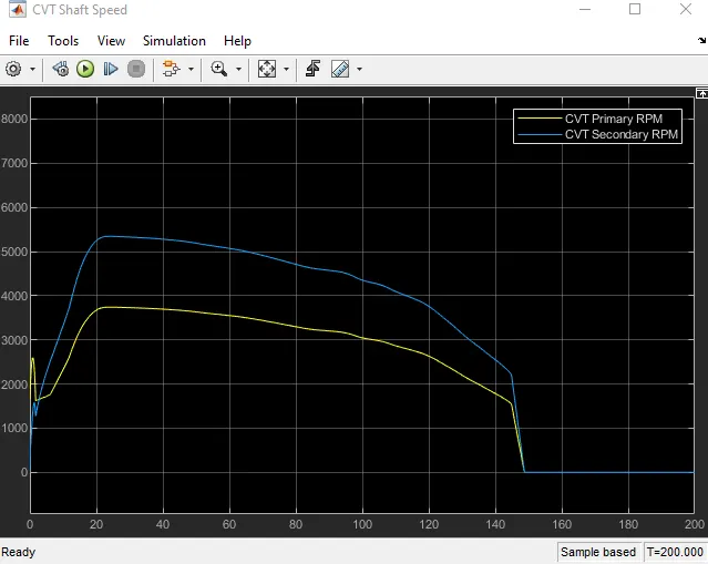
Results from signal builder without dashboard model
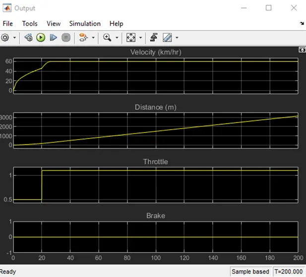
Conclusion
Thus, the application of the model is explained. From all these values we finally get the velocity in which our vehicle achieves can be determined. By modifying these parameters, we can build a perfect Baja vehicle using Simulink and Simulink driveline.Plotting between primary and seconday RPM is varied through the CVT ratio.