Week - 4
Aim:
- Implement control logic of a “washing machine” using Stateflow as per given sequence:
- Make a Simulink chart for the “Gear shift” logic
INTRODUCTION:
State Flow- its a technique of convert the chart into systematic arrangemnet, it provide graphical langauage that includes state transition diagram ,flow charts , stae transition table and trutgh table ,we can used it for how to matlab and simulink models react to input signal and tome based condition. it enables to design and development of supervisery control,task scheduling, fault management ,communication protocol,user interface and hybrid system.
State machine: its model of states that behave modeled as a set of states and transition between states its also called as reactive system , a finit state machine is a representation of an event driven system and in this system responds to an event by making transition from one state to another state, this transition when the defining changes are true, stateflow chart is graphical repesentation of finite state machine .
States: stages include used in system or operating modes of system.
part 1:conrol logic of washing machine
Objective:
- Implement control logic of a “washing machine” using Stateflow as per given sequence:
- If the power supply is available, the system gets activated
- If the Water supply is not available, stop the process & indicate through LED
- Soaking time should be 200s followed by Washing time of 100s.
- Then rinsing happens for next 20s & dryer runs for 50s
after completing all process turn on the finished LED.
Procedure:
state of washine machine includes:after electric supply on and check the water availabilty
following operation are done-
soaking: soakin the clothe in 200 sec as per requirment
washing:motors run in forward and backward direction to wash the clothes 00 sec.
Rinsing: drainig of water from the washing machinefor 20 sec,
Drying: after draining of water , dryer is used for 50 sec. to dry clothes.
for above process, i am using state flow chart method.
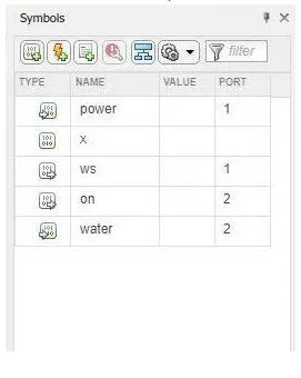
as per need used two input one is power supply other is water supply to check the given condition
- use two slider switch to switch on or off the power and water supply and connect to constant block to provide condition the washing machine by toggled switch.
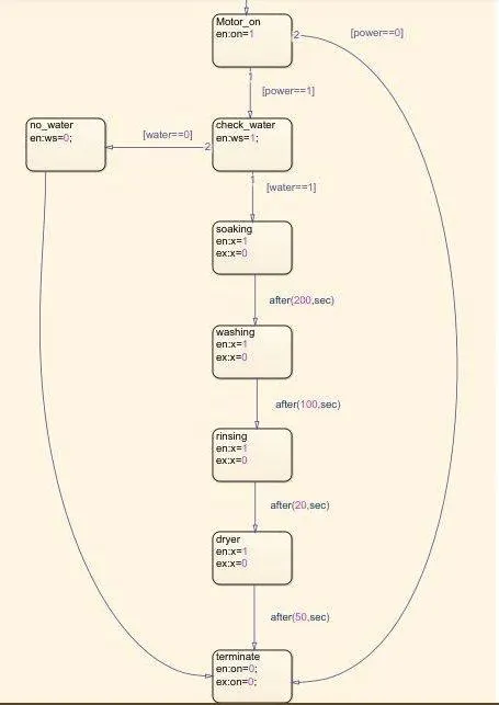
- in state flow chart we first apply condition for the motor on by putting 'power ==1'
- we check power supply here if its off then the process is terminated and if its on then move the other process.
- in next process ,made logic to check the water availabity , if there no water condition then [water==0], it shuts the process by termination block an dif water is available then [water==1] it process other process
- after fulfilling the condition of water supply all the process completed one by one with given time delay, i use after () command /condition .
for soaking 200 sec. ,washing 100sec. ,rinsing 20sec. and drying 50 sec.
afetr completing all stages it goes to termination block , the logic is made in such way that if ther is any false input condition provided, it shuts the process and terminates the system.
- Simulink state flow chart logic of washing machine:
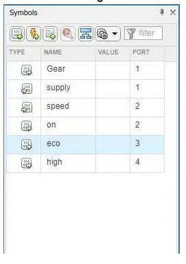
Variable chart: in symbol panel we can assign what are the input and output in the logic.
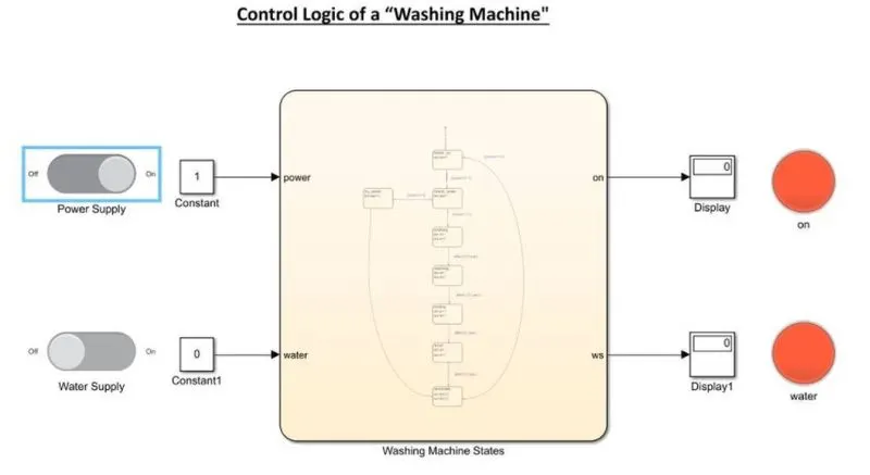
1. condition when both the power supply and water supply are off.

2.condition when power supply is on, and water supply is off.
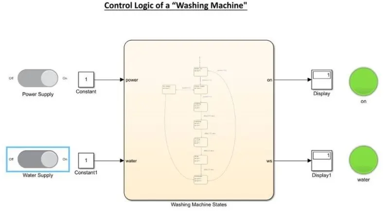
3, when both power and water supply is on.
part 2: Make simulink chart for gear shift logic.
Objective:
- Make a Simulink chart for the “Gear shift” logic as per below conditions:
Speed Range(kmph) Gear
0 to 15 1
16 to 25 2
26 to 40 3
41 to 60 4
Above 61 5
- Give speed input while the simulation is running & display the gear number. procedure:
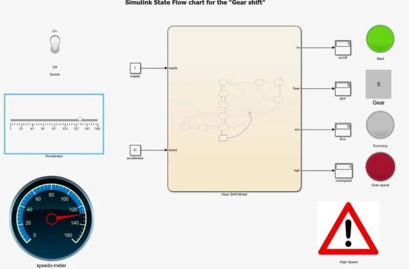
- in thixs gear shifting case ,we nnet to provide a contineous variable value for input as a speed , for that i use Slider block as an accelerator for speed change.
- as per our requirement ,we need to display gear noumber so Display block is used at the time of accleration so use infinite time(inf)
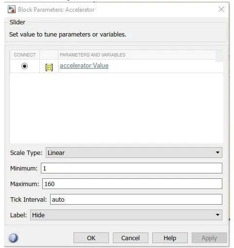
for compilation and change the speed manually on the slider block . - configur the slider block by providing the value min.=0,max=160, as the speed pf the vehicle .
- same values i configur to the gaude block (speedometer) to show the input.
- use lamp block to show the , if system is on or off,for economy mode and for the overspeed .
- for the overspeed ,i use an image to pop up as a sign of over speed on.
- the multistateimage block.
Slider configuration:
Gauge block configuration :
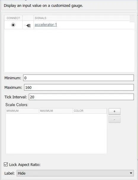
Both slider block and gauge block is connected to the input (accelerator),slider block used to determine the speed and gauge block display the speed, then use toggle swith blopck for to the input to on /off the system.as per requirement the gear no. should be visible as the speed changes for that use Display block at the result.
Simullink model when system is off:here use the condition as if the supply==0, it follows the cindition is true and it flows the circuit to engine off.
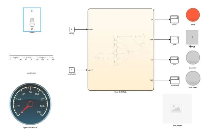
Simullink model when system is on:
here use the condition as if the supply==1, it follows the cindition is true and it flows the circuit to engine on. and green light is pou up when system is on.
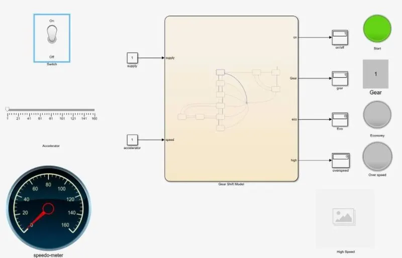
State flow chart or logic is used fir the system:
After providing the the supply , i provide the condition as if speed is greater than the equal to a particuar speed it will change the gear block ,so on increasing /decrasing the speed as an input , it proceed to the next stage.
then added a stage to show the economy mode on particular speed range , in that particular speed range of 50 to 80 speed ,green light blink on the lamp as output
same concept i used to show the overspeed sign on exceeding the speed above 120. so use multistateimage blocktopop up the display the alert sign overspeeding the limit.
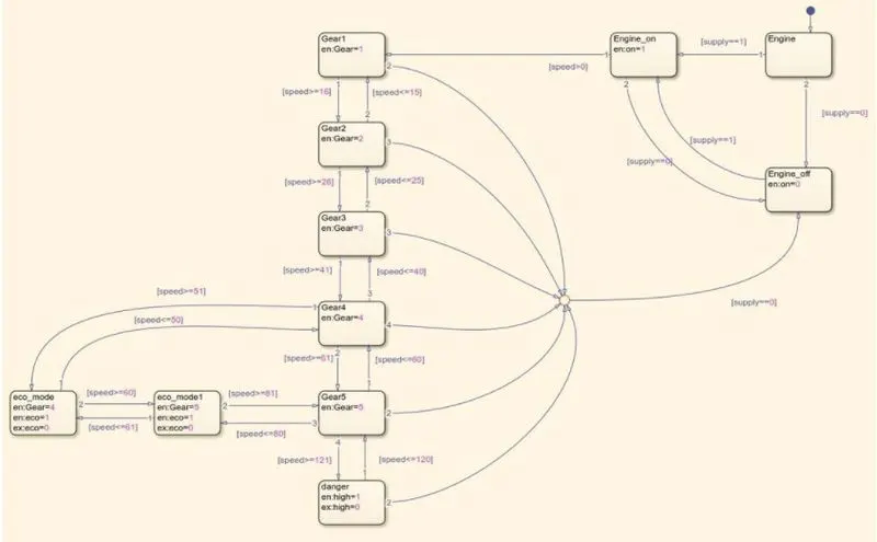
variable logic:
Shifting gear:
i put the run time infinity(inf),we can change the speed while simulation is running, on putting the engine condition ON,we change the speed limit on the slider block,as per given speed range.-
Speed Range(kmph) Gear
0 to 15 1
16 to 25 2
26 to 40 3
41 to 60 4
Above 61 5
to provide above condition and get the result speed should lie in between the range for particular gear .
on sliding the slide bar (for increasing/decrasing the speed) below are the output we get.
Model showing gear 1 for speed ranges 0-15:
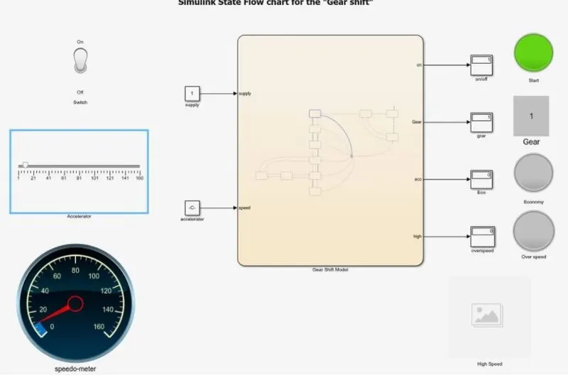
Model showing gear 2for speed ranges 16-25:
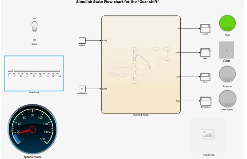
Model showing gear 3 for speed ranges 26-40:
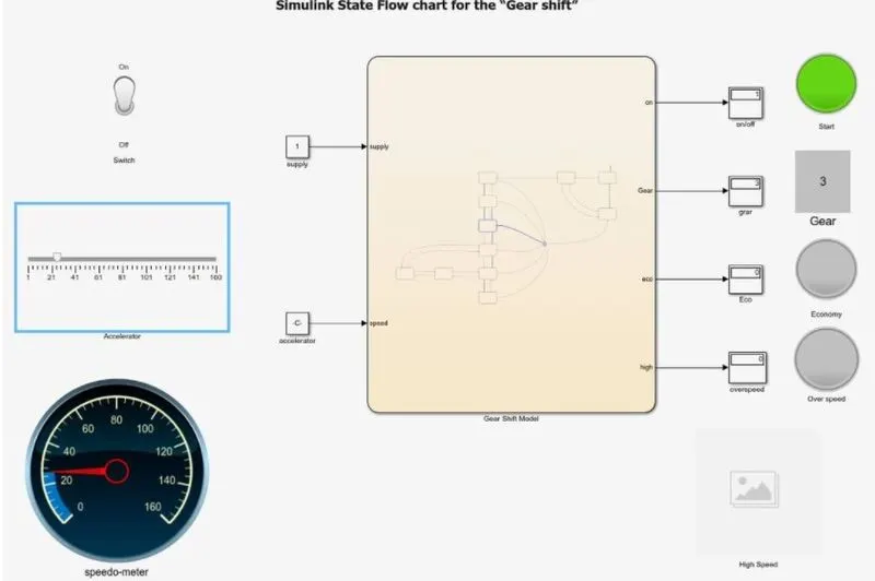
Model showing gear 4 for speed ranges 41-60:
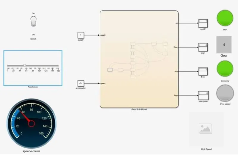
Model showing gear 5 for speed ranges above 60:
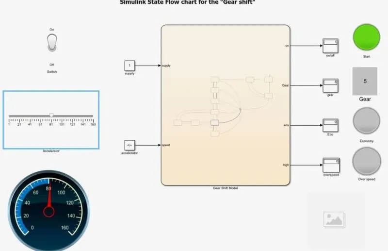
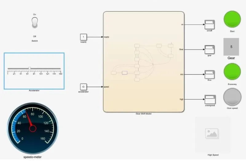
model showing economy mode in range of 50 to 60: i provide a sage on wich lamb block shows the green light as output which resemblke the economy mode .and this economy lies in the 4 and 5 gear,so it popup green light on lamp on both the gear.
Model showing oversopeed warning:
new stage for showing the overspeed warning on exceeding the 120 speed.,this warnig shows on multistateimage as output and the red colour on the lamp block.
Learning outcome:
- to understand the basic of state flow,state amchine,state machine,stages of system.
- we learn how logic is made and apply the condition to fulfill the requirment.
- we learn logic used in shifting the gear on changing the speed.