Week - 4
- Implement control logic of a “washing machine” using Stateflow as per the given sequence:
- If the power supply is available, the system gets activated
- If the Water supply is not available, stop the process & indicate through LED
- Soaking time should be 200s followed by Washing time of 100s.
- Then rinsing happens for next 20s & dryer runs for 50s
Aim:
A washing machine is used to clean various types of cloth without human interference. In now days washing machines have advanced settings in which we cannot stand near to the machine for the different steps to the washcloth. By programming the steps on a washing machine, it does steps according to program or according to user-defined flow chart steps.
There are four steps involved in every Washing Machine:
- Soaking
- Washing
- Rinsing
- Drying
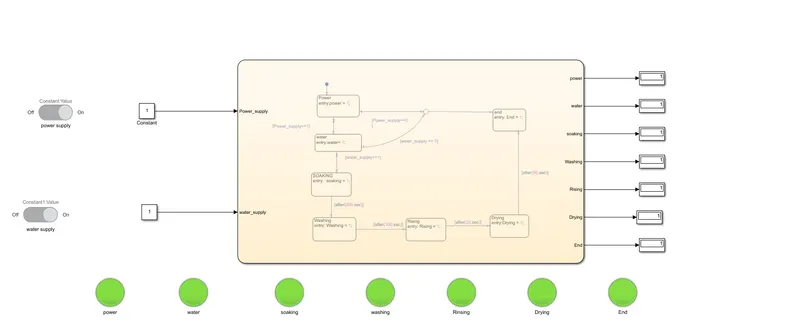
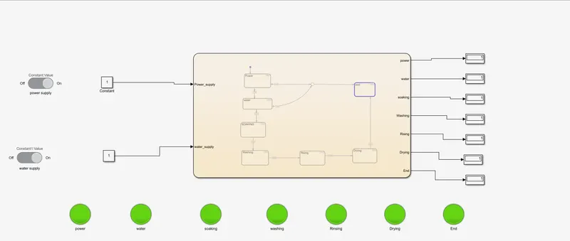
Simulink Model for Washing machine with state flow model:
- Toggle switch
- constant
- state flow chart
- Lamp
- Display
The toggle switch is used to give an input signal to the Constant Block.
Constant Block is used to give input to the input data which is assigned in state flow.
The state Flow chart is a predefined function, Based on these functions, only our model will run.
The lamp is used to Display which state the machine is running.
Flow chart for Washing Process:
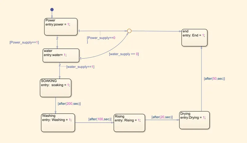
Delay times are mentioned in the question.
Simulink Model of Washing Machine:
Working Procedure:
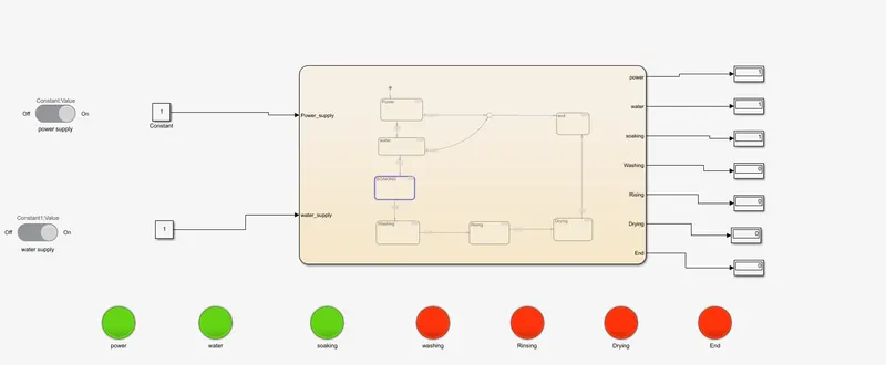
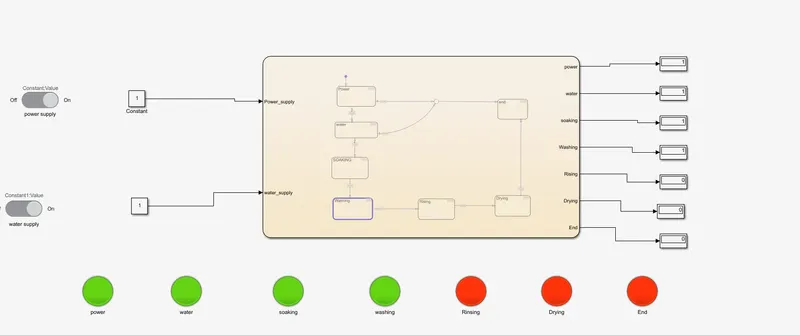
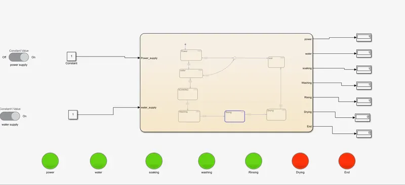
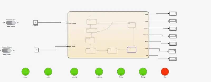
When the power and the Water supply are 1 condition then the flow of the program goes to the next state. If the Power is 1 and the water supply is 0 then the processes cannot continue to the next step the process will end. Both Inputs should be High is mandatory in our chart.
Inputs are high then the Soaking state will active for 200 sec, after 200-sec soaking state changes to the Washing state for 100 sec, after washing state it goes to rinsing state for 20 then it goes to drying state for 50 sec. And the process will end.
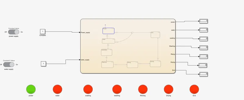
Output
Power on
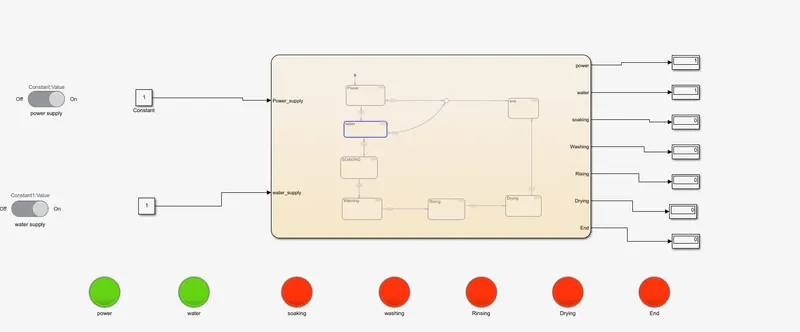
Water supply On
Soaking
Washing
Rinsing
Drying
End
2. Make a Simulink chart for the “Gear shift” logic as per the below conditions:
Speed Range(km) Gear
0 to 15 1
16 to 25 2
26 to 40 3
41 to 60 4
Above 61 5
Give speed input while the simulation is running & display the gear number.
Aim:
Prepare Simulink chart for the GEAR SHIFT
Simulink Model of Gear shift
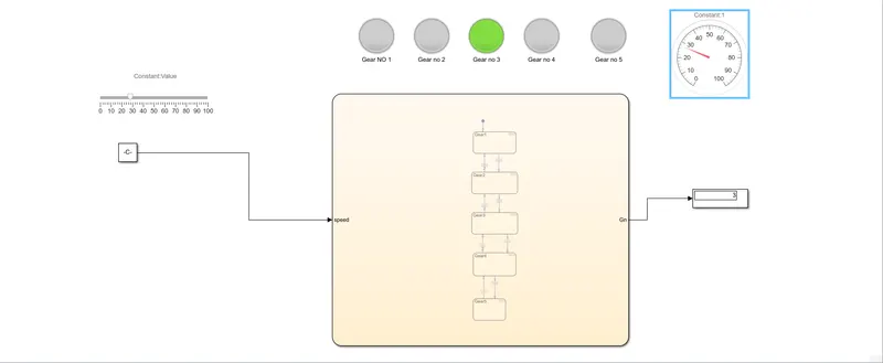
The purpose of a gearbox is to increase or reduce speed. As a result, torque output will be the inverse of the speed function. If the enclosed drive is a speed reducer (speed output is less than speed input), the torque output will increase; if the drive increases speed, the torque output will decrease.
Condition:
Speed Range(km) Gear
0 to 15 1
16 to 25 2
26 to 40 3
41 to 60 4
Above 61 5
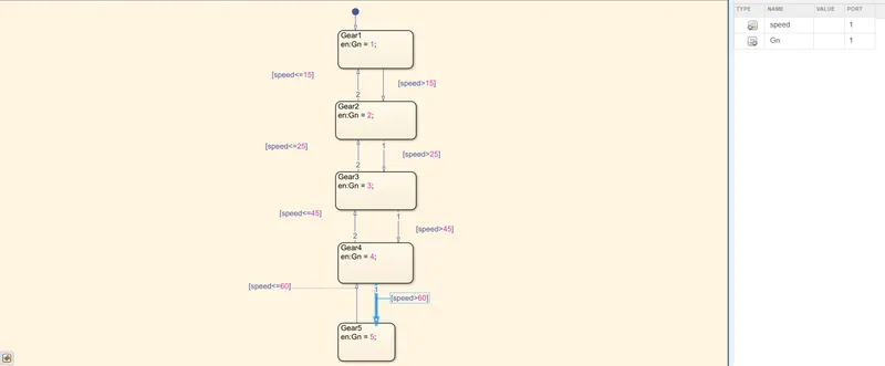
Flow chart:
we are using
Constant Block: Used as input to the chart.
slider Gain: Used to vary the speed
Display: Display show the Gear no
Flow chart: In the flow chart, we entered our condition.
Output :
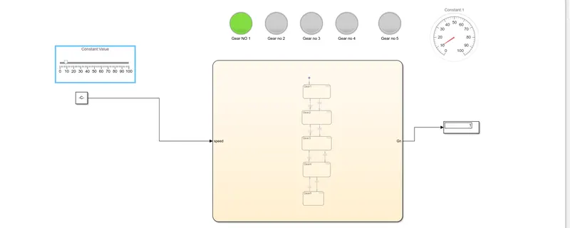
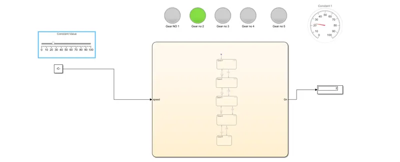
Keeping speed as 10:
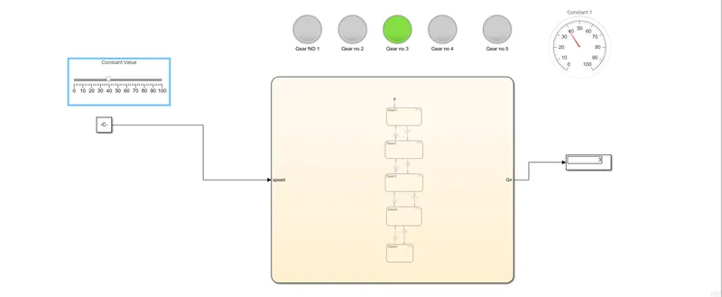
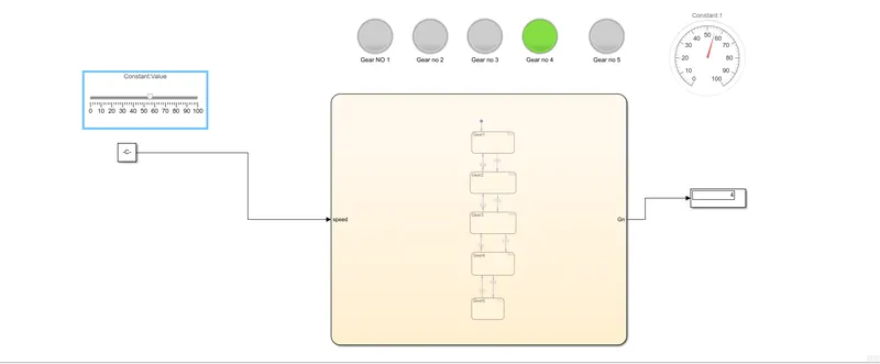
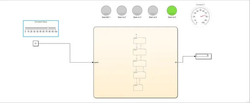
In-display shows, gear no 1, same time Gear no 1 lamp glow, speed meter show the input speed.
Keep speed as 23
keep speed as 40
keep speed as 55
Keep speed as 75
Result
Output condition shows system work as per the given condition.