Week -2
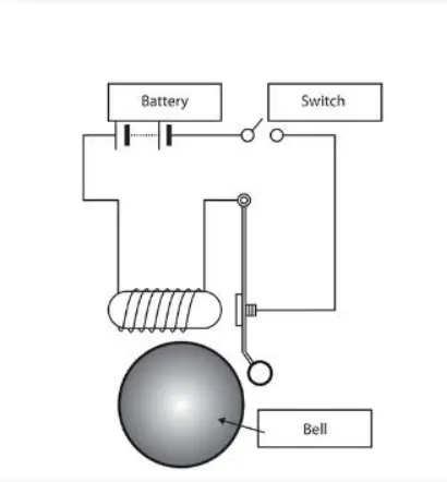
Aim:
Create the simulation to ring a bell for 2 sec and go to the off position for another 2 sec in a repeated manner using a solenoid valve.
Description:
To simulate the above condition we require the following Blocks:
- Pulse Generator
- Battery
- switch
- Electrical Reference
- solver configuration
- solenoid
- Ideal Translational Motion sensor
- Mechanical Translational Reference
- ps to Simulink converter
- Simulink to ps converter
Block Diagram:
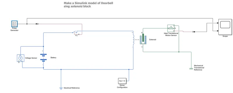
First, we are using a Battery source that is connected to the switch. The output signal from the pulse wave generator is connected to the switch control port. From switch is connected to the positive side of the solenoid and the negative side of the solenoid is connected to the negative side of the Battery. In the solenoid, R is connected to the R of the Motion sensor. output from the sensor is given to the ps to Simulink converter and then it is connected to the Scope. Electrical Reference is used on Electrical side and Mechanical reference is used on solenoid side
In the above Block, we are using Pulse generator Block to give a control signal to the switch. Now switch will open and close based on our criteria. Our criteria are to open the switch for 2sec and close for another 2 sec.
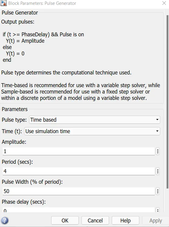
So, we were given a pulse generator with a period of 4, and pulse width is 50 percent.
Output Plot:
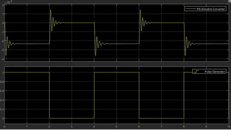
From the graph, we can observe that for the first two-sec pulse generated and we can see the output from the first graph the movement of the plunger. After 2-sec pulse becomes zero and the system return to 0. Hence we achieved the given condition
Use a thermistor to sense the temperature of a heater & turn on or turn off the fan
Aim:
Using a thermistor sensor by sensing the temperature of a heater to turn on and turn off the fan with the following condition,
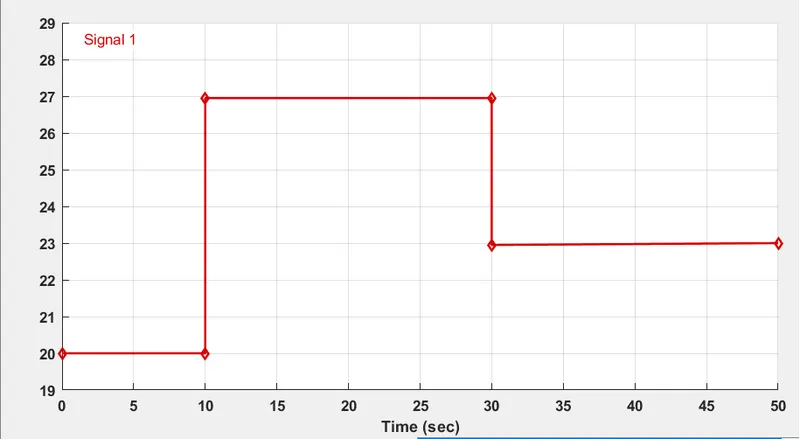
Temperature source: 20 °C from 0 to 10 seconds, 27 °C from 10 to 30 seconds, 23 °C from 30 to 50 seconds
Fan conditions: ON if the temperature above 25 °C, OFF otherwise
Block Diagram :
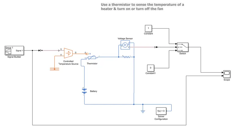
- Signal Builder
- controlled Temperature source
- Thermistor
- voltage sensor
- Battery
- Electrical Reference
- Switch
- solver configuration
- constant
- scope
These are the Blocks used to simulate a given experiment.
Description:
In the signal Builder, we have configured the Time and axis based on our criteria. In these Block, we require to generate the signal following as
T= 0 to 10 sec signal to 20
T=10 to 30 sec signal to 27
T =30 to 50 sec signal to 23
Switch configuration:
To control the switch we have to assign the threshold value. If we assign a threshold value, the switch will close when the control signal has the threshold value that we give in the parameter.
In this experiment, we found the threshold value by connecting the voltage source across the resistor, and the scope is connected to it.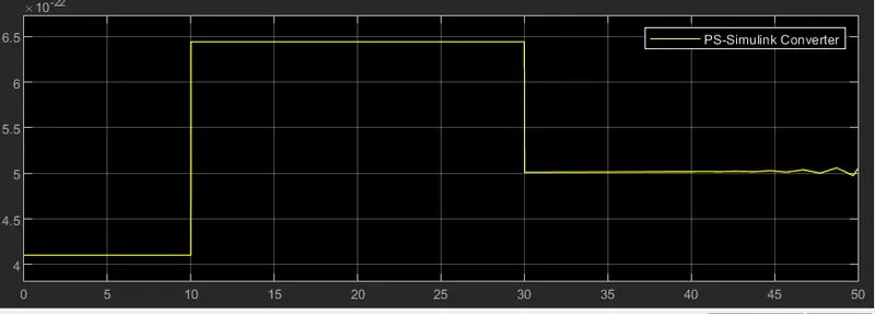
From the graph, we can observe that during 10 to 30 sec that means in 25 celsius the value of the threshold is 6.4*10^10-22 that was given in switch as the threshold value.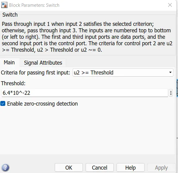
Output Plot
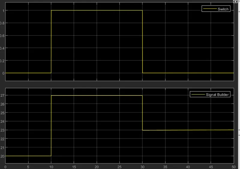
From the above graph, we can see that when the signal builder has a value greater than 25 celsius the switch is closed and have the value of 1 in the graph. If the valve is below then the switch is opened and the value in the graph is zero.