Week - 4
stateflow:stateflow enables you to design and develop supervisory control,task scheduling,fault management,communication protocols,user interfaces, and hybrid systems.simulink is used torespond to continuous changes in dynamic changes,stateflow is used to respond to instantaneous changes in dynamic changes
task1:
Implement control logic of a “washing machine” using Stateflow as per given sequence
given conditions:
If the power supply is available, the system gets activated
If the Water supply is not available, stop the process & indicate through LED
Soaking time should be 200s followed by Washing time of 100s.
Then rinsing happens for next 20s & dryer runs for 50s
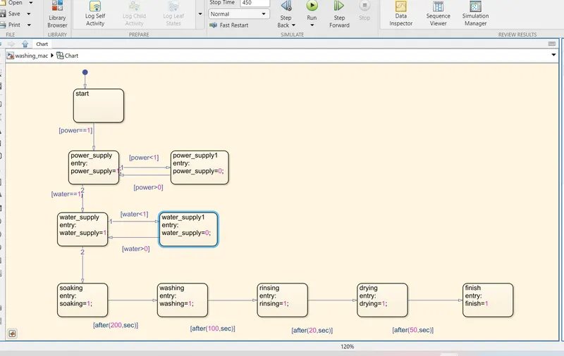
At first we have to create state flow for washing machine with given conditions in the question for that we have to take 'chart' block and that is changed into different setup with another color. in that state blocks are taken and given the conditions forward and reverse transitions for power supply and water supply as per the question
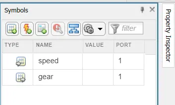
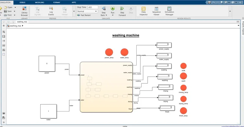
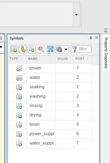
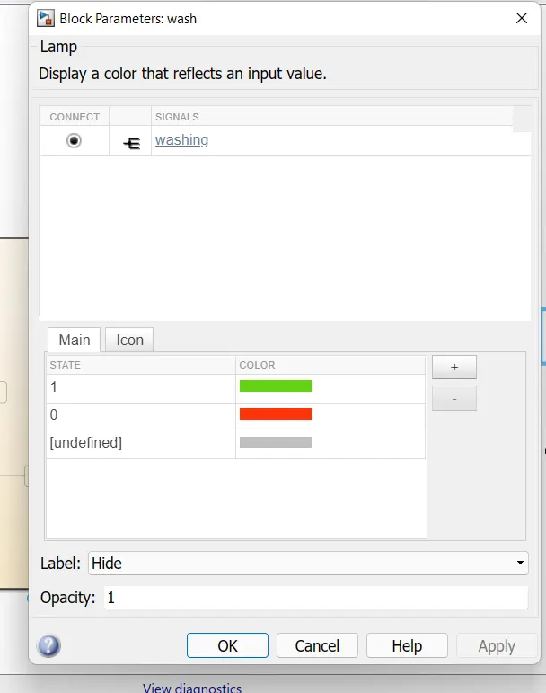
we have to take state blocks for soaking,washing,rinsing,drying,finishing.then we give the conditions by using after command '[after(time,sec)]' for time values and increase the stop time as 450. we take input as power and water,output are soaking washing rinsing drying finishing by selecting the option 'symbol panel'. and also we take 'lamp' block for indicating working conditions of power supply and water supply by returning into normal page we have to take constants as power and water inputs and display block for outputs
model:
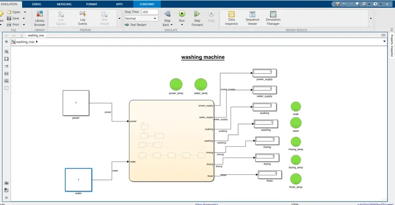
power supply is ON and water supply is OFF

both power and water is OFF
stateflow:
symbolspane:
lamp connection:
task2:
GEAR SHIFT:
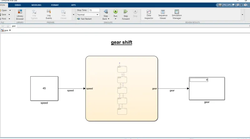
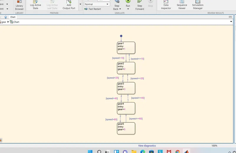
we have to take chart block in simulink then we use state block and give the below conditions for several blocks named as gears. in this flow we use both forward and reverse transitions with conditions lets take speed as input and gear as output.we use constant block as input for speed and display block is taken as output for gear number and we used stop time as 70 because of speed is above 60 in the question
Make a Simulink chart for the “Gear shift” logic as per below conditions:
Speed Range(kmph) Gear
0 to 15 1
16 to 25 2
26 to 40 3
41 to 60 4
Above 61 5
model:
state flow:
symbols pane: