Week - 4
Report
AIM:
- Implement control logic of a washing machine using Stateflow.
- Make a Simulink chart for the Gear shift logic as per given conditions.
1] Implement control logic of a “washing machine” using Stateflow as per given sequence:
Steps of Washing Machine:
- Soaking
- Washing
- Rinsing
- Drying
Given Condition:
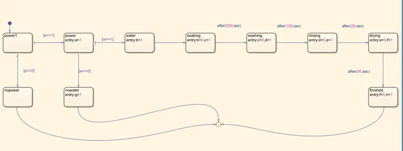
- If power is ON,then system should be activated.
- The process should be taken place when water supply is available otherwise stop the process with indicating LED
- Soaking time is 200 sec.
- Washing time is 100 sec.
- Rinsing time is 20 sec.
- Drying time is for 50sec.
- After completion of all the process finished then LED should glow.
Simulink model:
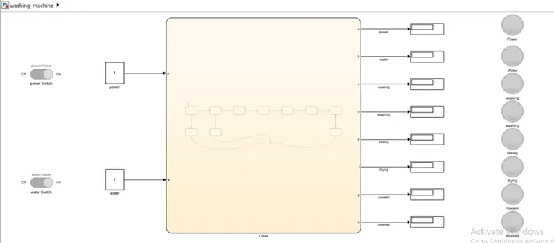
Chart:
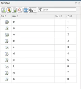
parameter in chart:
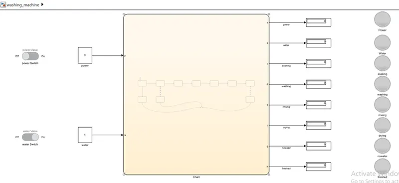
condition:
condition 1: when the power is OFF and water supply is ON.the process does not take place even the water supply is ON.process take place only when the power is ON.
condition 2: when the power is ON and water supply is OFF,since the power is ON but water supply is unavailable washing does not take place and no water lamp is on.
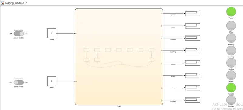
obeservation:
step 1: when the power and water supply is on.soaking takes place for 200sec.soaking lamp light during this process.
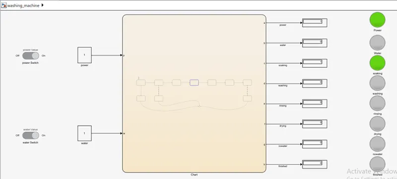
step 2: the next step is washing and its take place for 100sec.and washing lamp light during this process.
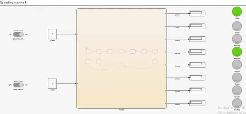
step 3: the next step is rinsing and its take place for 20 sec.and rinsing lamp light during this process.
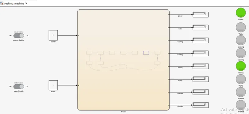
step 4: the next step is drying and its take place for 50 sec.and drying lamp light during this process.
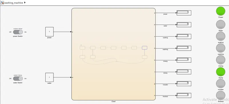
step 5: after completion of all process,finished lamp is lighting.
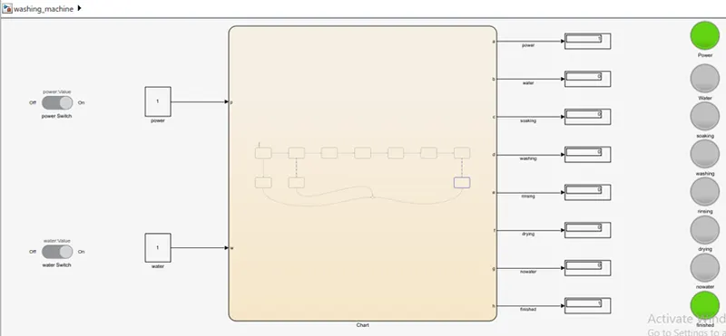
conclusion: hence state flow logic for washing machine is created in simulink.
2] Make a Simulink chart for the “Gear shift” logic as per below conditions:
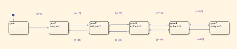
Speed Range(kmph) Gear
0 to 15 1
16 to 25 2
26 to 40 3
41 to 60 4
Above 61 5
Give speed input while the simulation is running & display the gear number.
Simulink Model:
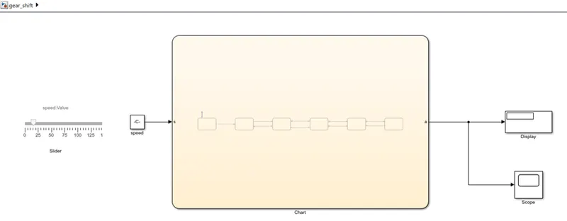
Chart:
Parameter:
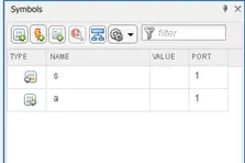
observations:
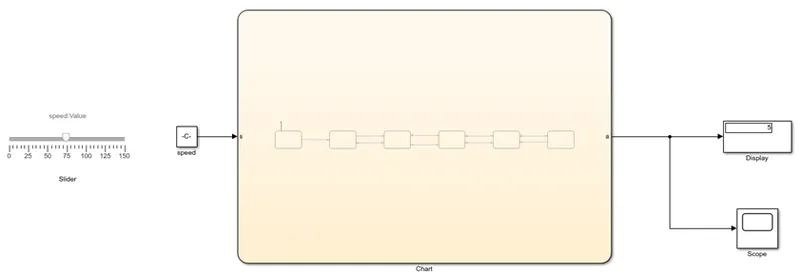
Gear 1: when the value for speed is changed in between 0-15, the display show 1.
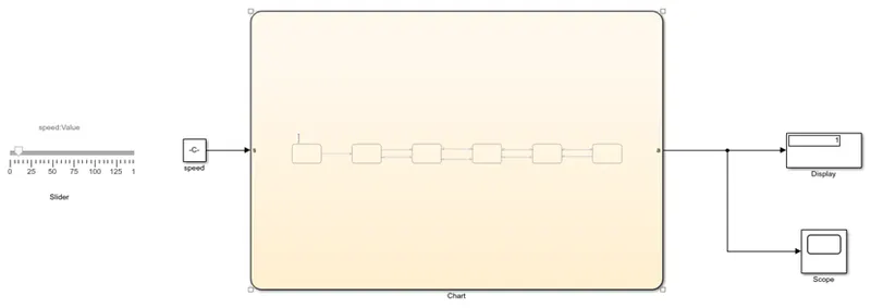
Gear 2: when the value for speed is changed in between 16-25, the display show 2.
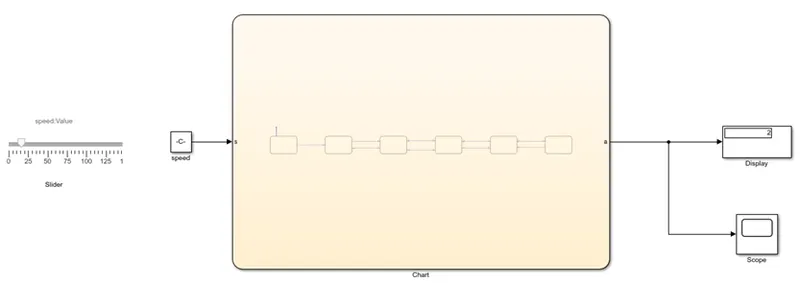
Gear 3: when the value for speed is changed in between 26-40, the display show 3.
Gear 4: when the value for speed is changed in between 41-60, the display show 4.
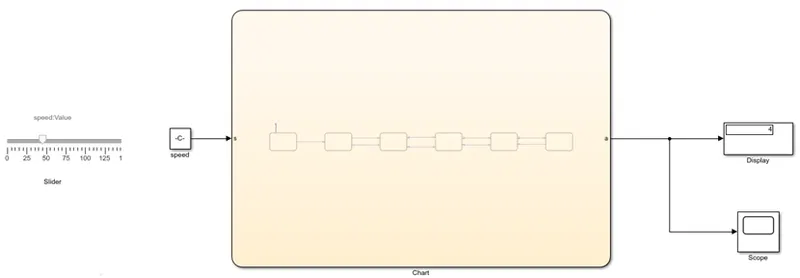
Gear 5: when the value for speed is changed for above 60, the display show 5.
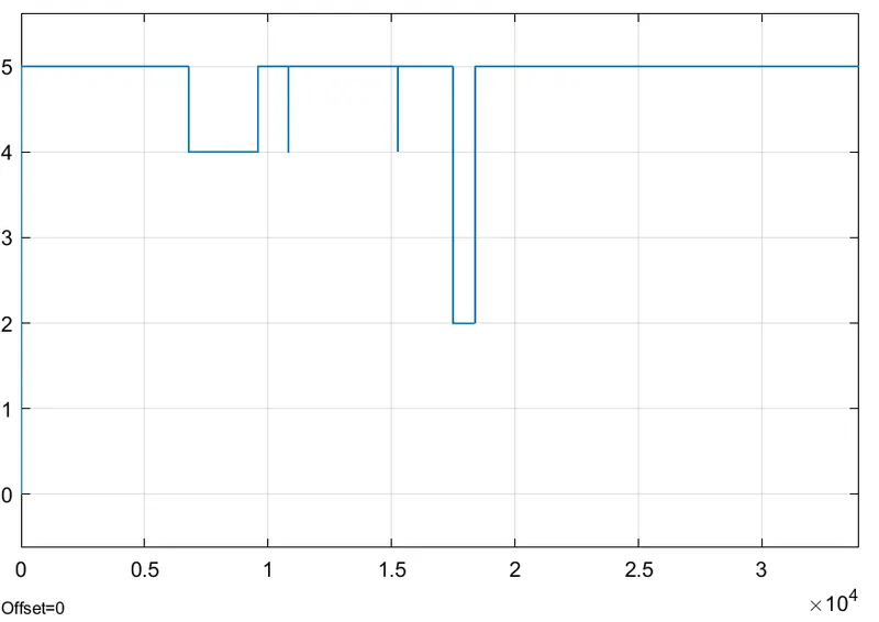
scope: output is plotted when the gear shifting is done from higher to lower and vise-versa.
conclusion: therefor the state flow logic is written for gear shift in simulink.