Week - 4
AIM:
STUDY 1:
- Implement control logic of a “washing machine” using Stateflow as per given sequence:
- If the power supply is available, the system gets activated
- If the Water supply is not available, stop the process & indicate through LED
- Soaking time should be 200s followed by Washing time of 100s.
- Then rinsing happens for next 20s & dryer runs for 50s
After all the processes have completed turn on the finished LED
STUDY 2:
2. Make a Simulink chart for the “Gear shift” logic as per below conditions:
Speed Range(kmph) Gear
0 to 15 1
16 to 25 2
26 to 40 3
41 to 60 4
Above 61 5
Give speed input while the simulation is running & display the gear number.
PROCEDURE:
STUDY 1:
Implement control logic of a “washing machine” using Stateflow as per given sequence:
- If the power supply is available, the system gets activated
- If the Water supply is not available, stop the process & indicate through LED
- Soaking time should be 200s followed by Washing time of 100s.
- Then rinsing happens for next 20s & dryer runs for 50s
After all the processes have completed turn on the finished LED
SIMULINK STATEFLOW MODEL:
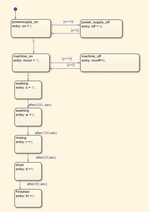
Below is the control logic for washing machine simulation:
EXPLANATION:
- Give inputs x and y where x represents the power supply on and off and y represents the machine on and off according to water supply.
- If x is 1 power supply is on and x is 0 power supply is off.
- y is 1 if water supply is on and y is 0 water supply is off.
- the conditions are given using the state and arrow blocks.
- If power and water supply is on the washing machine run on different states
- State followed by soaking for 200 secs,wash for 100 secs,rinsing for 20 secs and dryer for 50 secs by give condition after(50,sec).
- Then finished state block is given.
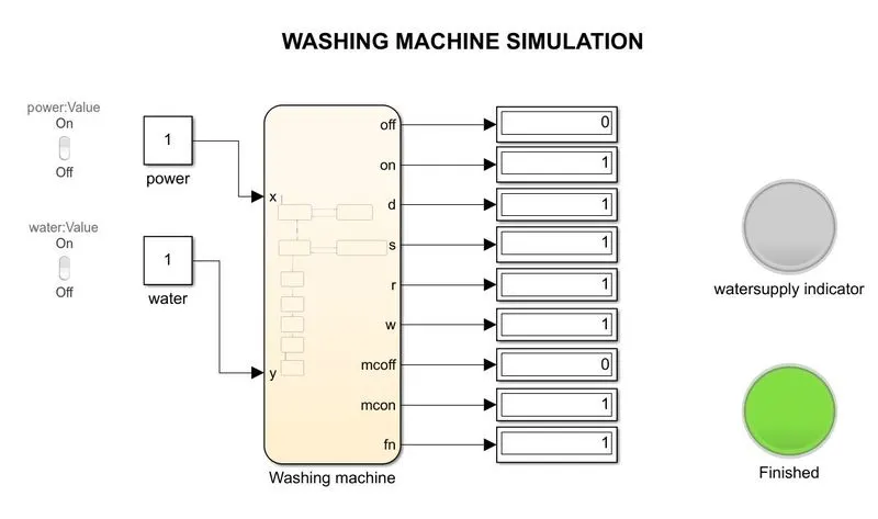
- give constant block for power and water supply input
- use dashboard lamp and switches for indicating the light and positions.
The below simulink model shows the finished light indicator is on after completing full cycle.
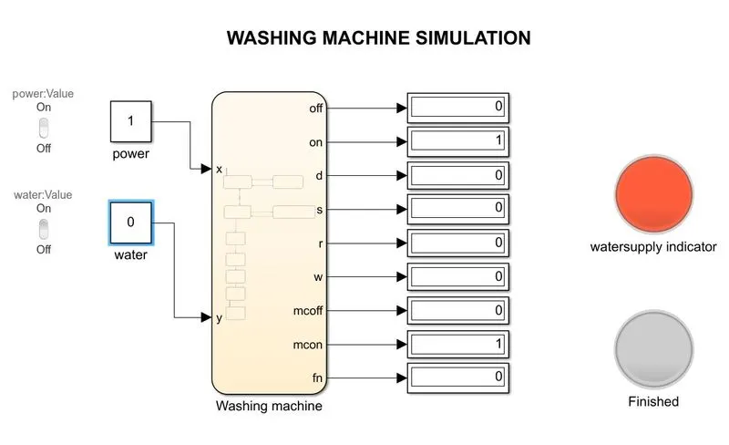
The below simulink model shows the water supply is off and lamp of watersupply indicator is on and machine is stopped.
CONCLUSION OF STUDY 1:
Washing machine simulation is done using the chart (stateflow) and lamp dashboard block is added to indicate the finished state and water supply indicaor.
STUDY 2:
Make a Simulink chart for the “Gear shift” logic as per below conditions:
Speed Range(kmph) Gear
0 to 15 1
16 to 25 2
26 to 40 3
41 to 60 4
Above 61 5
Give speed input while the simulation is running & display the gear number.
SIMULINK STATEFLOW MODEL:
The below model shows the gear shift simulation using stateflow chart and dashboard blocks:
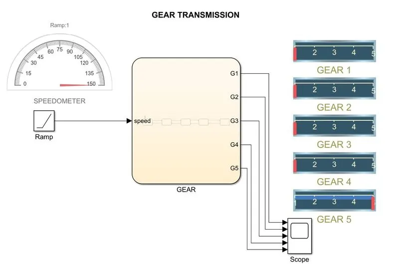
half gauge dashboard block is connected to ramp for getting the input of speed as simulation.
horizontal gauge dashboard block is gear 1 to 5 to show the gear shift simulation.
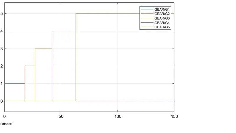
outputs of gear 1 to 5 are connected to scope to get the results as scope.
Stateflow explanation:

- Gear shift from gear 1 to 5 is given using the state blocks
- entry and exit condition is given for all the state bloks
- The range of speed for gear 1 to 5 is given as conditions for shifting the gear.
Scope result of gear shift:
CONCLUSION OF STUDY 2:
The gear shift simulation is done using the simulink stateflow chart and dashboard blocks and gear numbers are displayed.
RESULT:
Washing machine simulation is done using the chart (stateflow) and lamp dashboard block is added to indicate the finished state and water supply indicaor.
The gear shift simulation is done using the simulink stateflow chart and dashboard blocks and gear numbers are displayed.