Week - 4
Task 1
Aim : To implement control logic of a “washing machine” using Stateflow as per given sequence as a simulink model.
Objective :
Implement control logic of a “washing machine” using Stateflow as per given sequence:
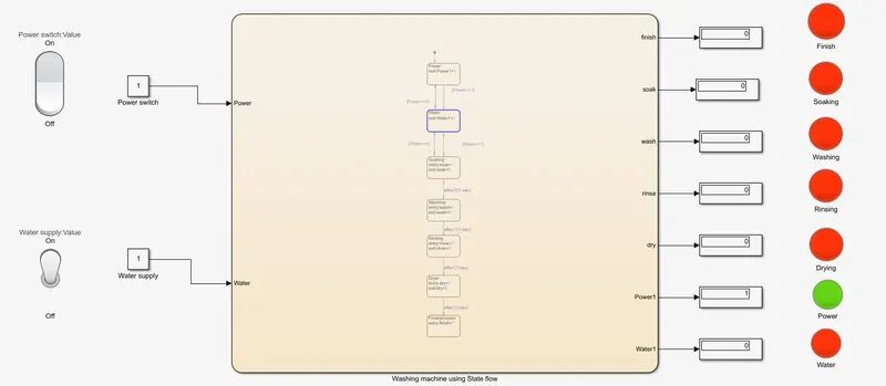
- If the power supply is available, the system gets activated
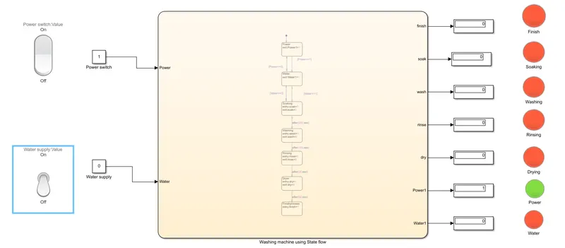
- If the Water supply is not available, stop the process & indicate through LED
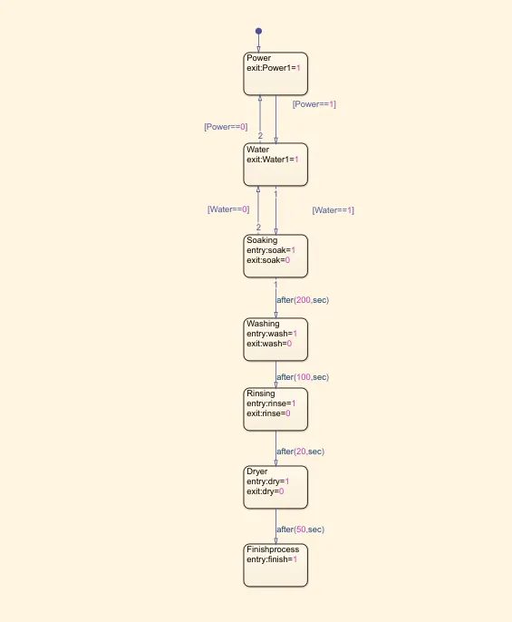
- Soaking time should be 200s followed by Washing time of 100s.
- Then rinsing happens for next 20s & dryer runs for 50s
After all the processes have completed turn on the finished LED
Theory :
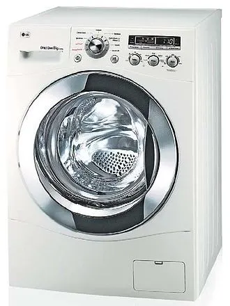
A washing machine (laundry machine, clothes washer, washer, or simply wash) is a home appliance used to wash laundry. The term is mostly applied to machines that use water as opposed to dry cleaning (which uses alternative cleaning fluids and is performed by specialist businesses) or ultrasonic cleaners. The user adds laundry detergent, which is sold in liquid or powder form, to the wash water.
Simulink model to implement control logic of a “washing machine” using Stateflow :
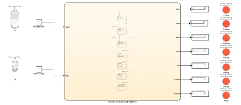
Parameters :
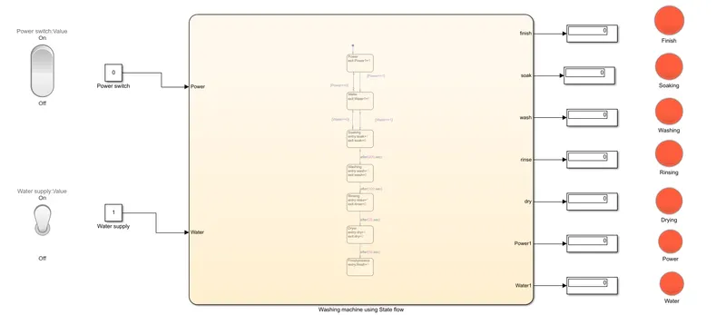
- The value '1' indicates there is input.
- The value '0' indicates there is no input.
- The 'green' light indicates the task is in progress.
- The 'red' light indicates the task is Finished.
The chart diagram of Washing machine :
Symbols :
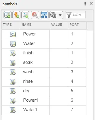
In this, we have given Power and Water as input data and
We have given finish, soak, wash, rinse, dry, Power1 and Water1 as output data.
Simulation time :
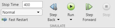
Explanation and Output :
When the Power supply condition is off :
When the Water supply is off :
When the Power supply and Water supply are on condition and execution :
Step 1 :
Step 2 :
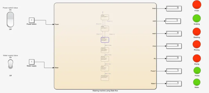
Step 3 :
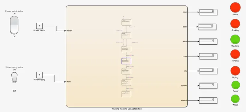
Step 4 :
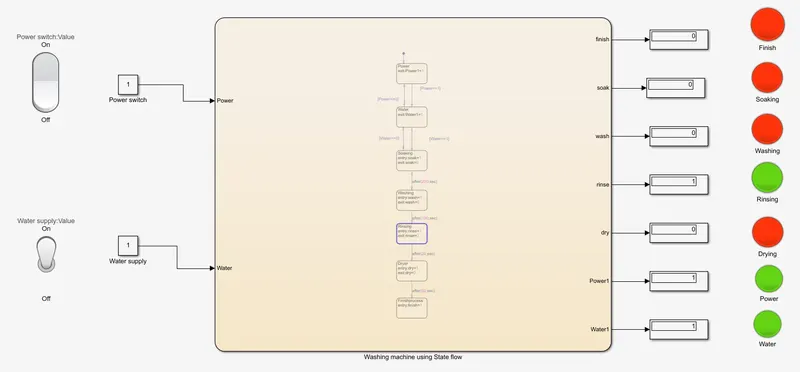
Step 5 :
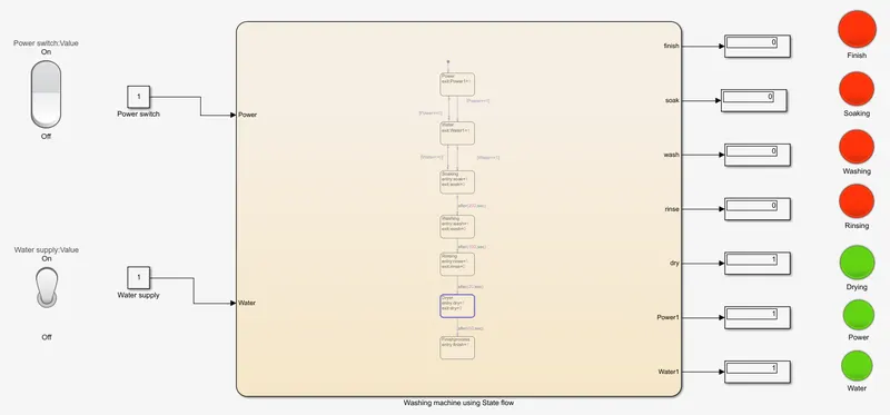
Step 6 :
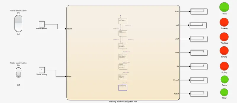
Finally the lamp indicating green tells that the cycle is Finished.
Conclusion :
The simulation of Washing machine using state flow using simulink is done sucessfully.
Task 2
Aim : To make a Simulink chart for the “Gear shift” logic as per below conditions as a simulink model.
Objective :
Make a Simulink chart for the “Gear shift” logic as per below conditions:
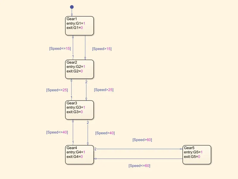
Speed Range(kmph) Gear
0 to 15 1
16 to 25 2
26 to 40 3
41 to 60 4
Above 61 5
Give speed input while the simulation is running & display the gear number.
Theory :
A transmission is a machine in a power transmission system, which provides controlled application of power. Often the term 5-speed transmission refers simply to the gearbox, that uses gears and gear train to provide speed and torque block conversions from a rotating power source to another device.
The term transmission properly refers to the whole drivetrain, including clutch, gearbox, prop shaft (for rear-wheel drive vehicles), differential, and final drive shafts.
The most common use is in motor vehicles, where the transmission adapts the output of the internal combustion engines to the drive wheels. Such engines need to operate at a relatively high rotational speed, which is inappropriate for starting, stopping, and slower travel. The transmission reduces the higher engine speed to the slower wheel speed, increasing torquein the process. Transmissions are also used on pedal bicycles, fixed machines, and where different rotational speeds and torques are adapted.
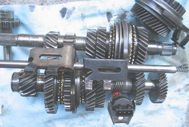
Simulink chart for the “Gear shift” :
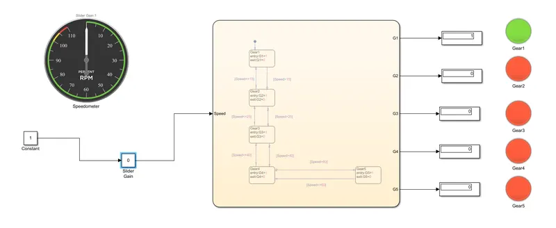
Chart diagram :
Prameters :
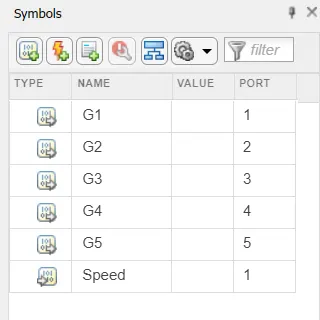
Input data : Speed
Output data : G1, G2, G3, G4, G5
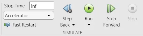
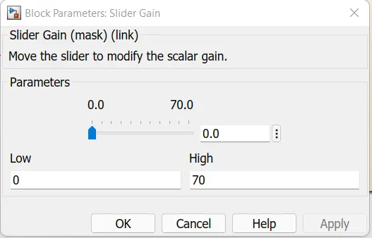
Here the time is given as infinity to control the speed using the slider gain.
Output and explanation :
1. When the speed is in the range of 0 to 15 the Gear 1 is used :
Speed : 12kmph
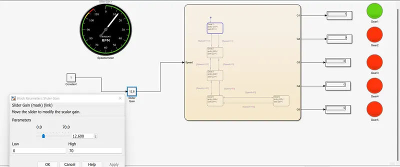
So, the green lamp indicator show that gear 1 is used.
2. When the speed is in the range of 16 to 25 the Gear 2 is used :
Speed : 18kmph
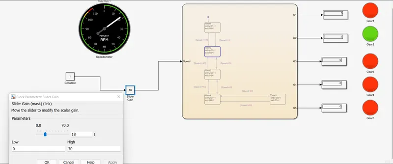
So, the green lamp indicator show that gear 2 is used.
2. When the speed is in the range of 26 to 40 the Gear 3 is used :
Speed : 37kmph
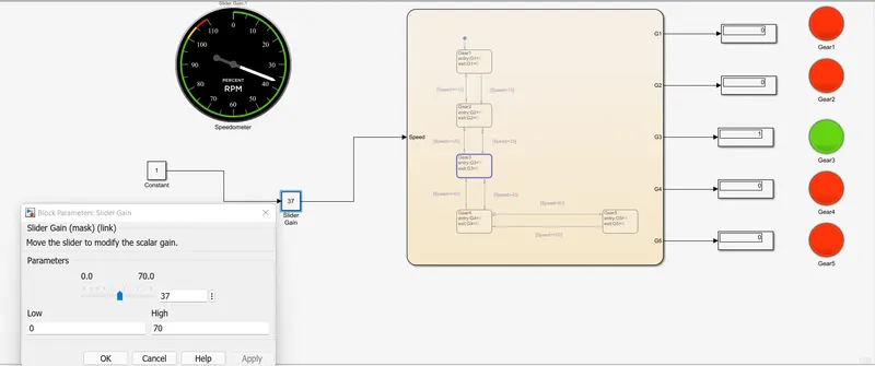
So, the green lamp indicator show that gear 3 is used.
2. When the speed is in the range of 41 to 60 the Gear 4 is used :
Speed : 51kmph
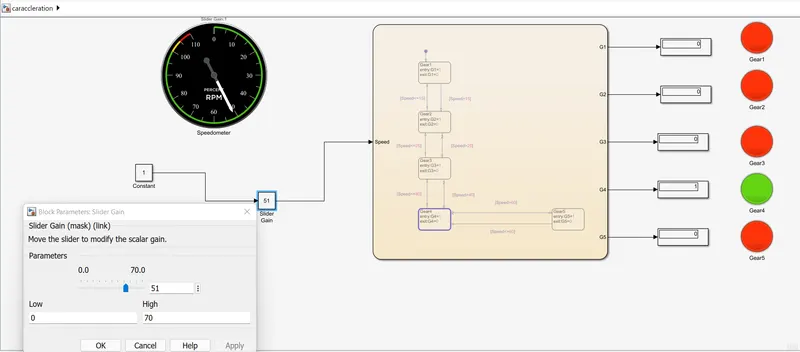
So, the green lamp indicator show that gear 4 is used.
2. When the speed is in the range of 60 and above the Gear 5 is used :
Speed : 70kmph
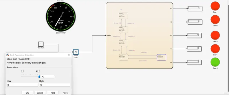
So, the green lamp indicator show that gear 5 is used.
Similarly when the speed is decreased the gear also automatically changes to the corresponding speed because we have set the condition in that way.
Conclusion :
Simulink chart for the “Gear shift” logic as per below conditions as a simulink model is done sucessfullly.