Week - 4
QUESTION 1
Objective :
To implement control logic of a “washing machine” using State flow as per given sequence
Conditions to be satisfied
- If the power supply is available, the system gets activated
- If the Water supply is not available, stop the process & indicate through LED
- Soaking time should be 200s followed by washing time of 100s.
- Then rinsing happens for next 20s & dryer runs for 50s
State Flow Logic :
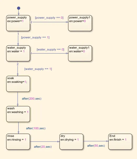
The state flow provides a graphical language that state transition diagrams, flow charts, state transition tables, and truth tables. The state flow describes the MATLAB algorithms and Simulink, and their reactions to the given inputs and conditions provided.
The logic is written in such a way that, satisfying the conditions mentioned. When there is no power supply, the system is completely inactive. When there is no water supply, It indicates red lamp. Also, when power and water is provided for the system, all the processes are carried out sequentially. The soaking is done for 200 seconds, followed by washing for 100 seconds. After washing is done, rinsing takes place for 20 seconds and finally drying takes 50 seconds. When all operations are performed successfully, a green lamp is indicated under finish.
Simulink Model :
Arrangement of various Simulink blocks
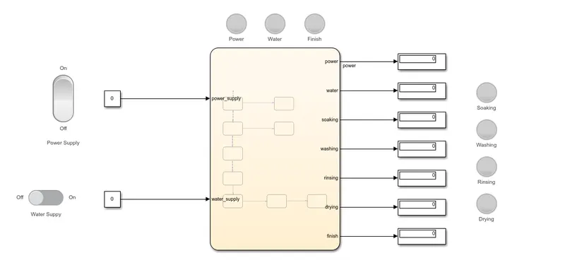
The system consist of two constant blocks which are controlled by the sliding switch and toggle switch. The both constants determine the power and water supply in the system.
If the toggle switch turned ON, the power supply constant value become, which indicates the flow of the current. Similarly, same thing happens for the water supply also.
The lamps are connected to the various stages of the operations performed in the system. They are configured to match perfectly with the state and also proper color indication.
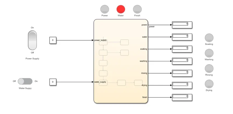
All the lamps are connected to the display state, if the value at display is 1, the lamp get activated. For water supply, the value is zero, i.e., no water supply indicated by the red color lamp.
When there is no power and water supply
When power is given, and water supply is turned off
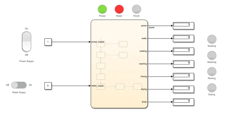
The green color lamp indicates that the power supply is given to the system. But the red color lamp is indicated that no water supply is provided to the system.
When both power and water are turned ON
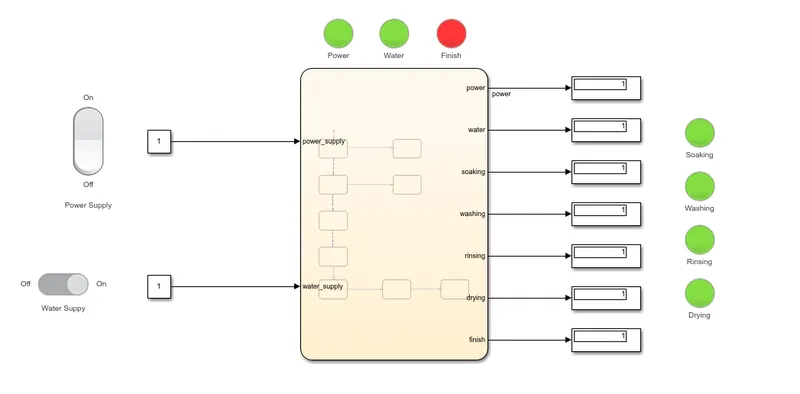
All the lamps are lighted, indicating that are processes are finished. Finally, a red color lamp lights at the finish, which indicates that the process is finished.
Conclusion :
Hence, the state flow logic for the washing machine is created successfully by satisfying the given conditions.
QUESTION 2
Objective :
To create a Simulink chart for the “Gear shift” logic as per given conditions
Conditions given
Speed Range(kmph) Gear
0 to 15 1
16 to 25 2
26 to 40 3
41 to 60 4
Above 61 5
Give speed input while the simulation is running & display the gear number.
Stateflow logic :
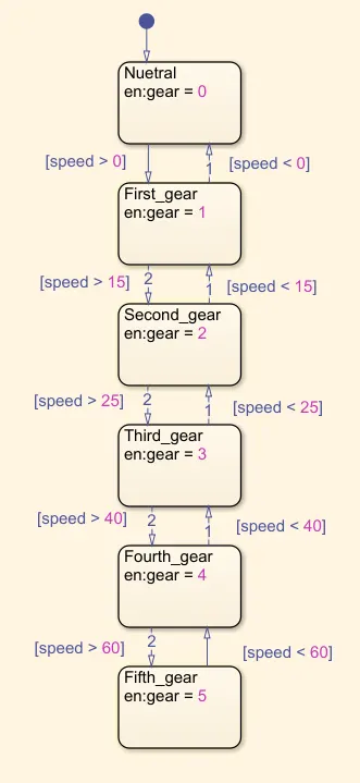
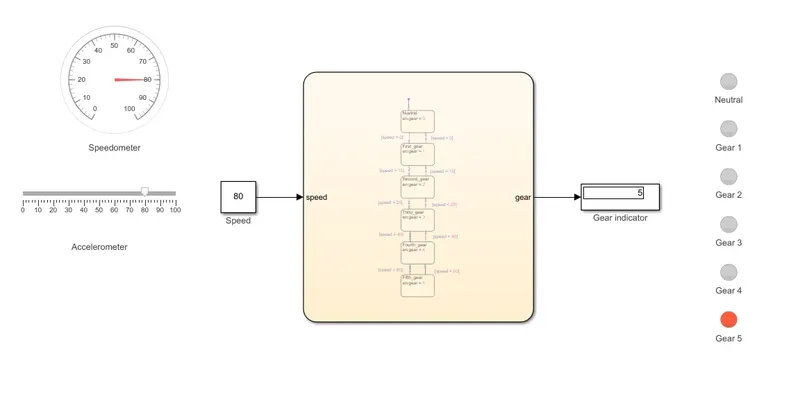
The logic used here is that if the specified speed enters into the block, it will check whether the limits of the blocks. For example, if the speed given is 18 kmph, it will enter the first block whose exit condition is greater than zero. Then it will move to the next block. Here also, the exit condition is greater than 15 kmph. Also, the condition is not satisfied, then will flow into the next block. Here the exit condition is greater than 25 kmph. Therefore, the flow stopped here and block number is displayed on the display.
The input and output conditions are given to each block. Depending upon the given speed, the gear is changed, thus the gear number is displayed on the display and indicated by light.
Simulink Model :
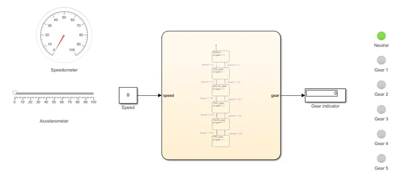
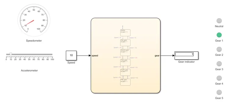
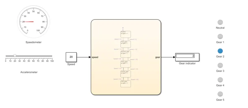
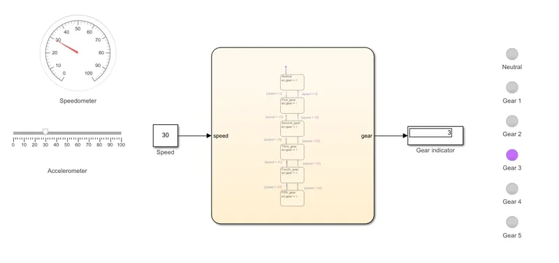
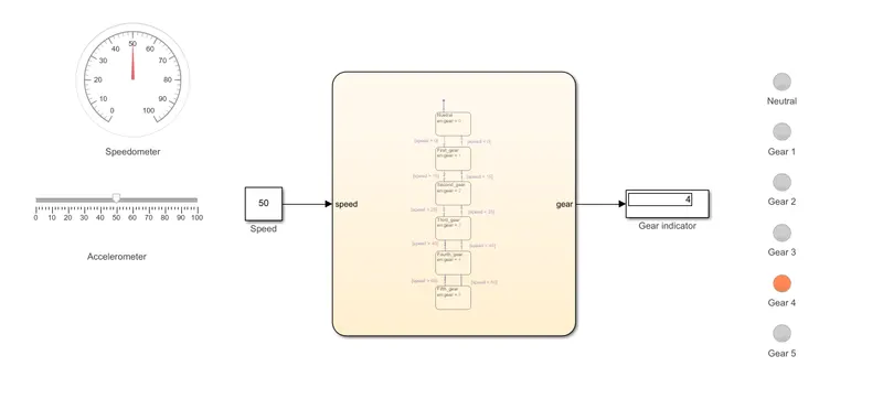
The Simulink blocks used are gauge for speed measurement, slider to illustrate the speed of the engine, constant block to take the value of the slider switch. A display is used to display the gear position.
Neutral, when vehicle is in idle position
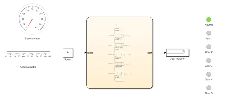
First gear, when speed is between 0 and 15 Kmph
Second gear, when speed is between 16 and 25 Kmph
Third gear, when speed is between 26 and 40 Kmph
Fourth gear, when speed is between 41 and 60 Kmph
Fifth gear when speed is above 61 Kmph
Conclusion :
Hence, the state flow logic for the gear shifting is created successfully by satisfying the given conditions.
Thank You