Week - 4
QUESTION 1:
- Implement control logic of a “washing machine” using Stateflow as per given sequence:
- If the power supply is available, the system gets activated
- If the Water supply is not available, stop the process & indicate through LED
- Soaking time should be 200s followed by Washing time of 100s.
- Then rinsing happens for next 20s & dryer runs for 50s
After all the processes have completed turn on the finished LED
AIM: To implement a logic of ''Washing Machine'' to follow given conditions.
WORKING: A Machine that washes clothes automatically. A typical front-loader washing machine. A washing machine ( laundry machine, clothes washer, or washer) is a home appliance used to wash laundry.
The washing machines have different kinds of settings related to time of washing, materials, water quantity, process, etc
Also, It have some process sequence that are filling of water, mixing of detergent, soaking, washing, rinsing, drying....etc.
Here in matlab simulink a basic processes model is implemented.
REPRESENTATION OF BLOCKS:
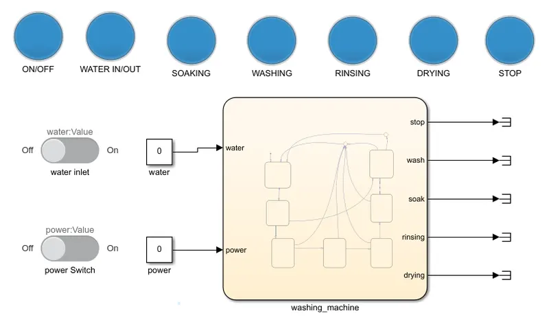
- SLIDER SWITCH: This switch is used for switching the power and other. it is a animation dashboard block.
- LAMP INDICATOR: A lamp lights when the input is high other wise it is in off condition.
- CONSTANT BLOCK: This block is used for assigning of inputs to the chart block.
- TERMINATOR : A terminator block terminates the process. this block is used for terminating the process.
- CHART BLOCK:To model conditional, event-based, and time-based logic for periodic or continuous-time Simulink algorithms, use the new function to create a Stateflow chart that you can simulate as a block in a Simulink model.
STATEFLOW CHART:
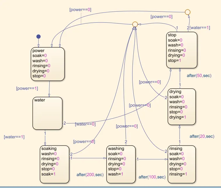
In this chart 7 flow blocks are used and 2 references that are interlinked based on logic, 2 input conditions that are power and water, here we write a condition based high and low logic procedure. also provide some time delays in between process sequence blocks.
BASIC PROCESS:
According to given question the process is represented in chart block, A default node and the blocks assigned is power, water, soaking, washing, rinsing, drying, stop/ finish sequence respectively...
some conditions are dominated this process.so, based on condition providing some logics and time delay.
If the power supply is available, the system gets activated. If the Water supply is not available, stop the process & indicate through LED. Soaking time should be 200s followed by Washing time of 100s. Then rinsing happens for next 20s & dryer runs for 50s. Finally all the process is completed and its indecates stop through LED on.
ASSIGNING OF INPUTS AND OUTPUTS:
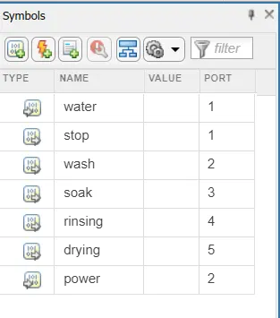
water, power are the input data,
remaining parameters are output data.
PROCEDURE STEP BY STEP: Initially put the stop time is infinite (inf), animation range mode is slow, then press the simulation.
- POWER ON : When power switch is operates off to on condition the lamp glows blue to green that means ON condition of washing machine. Remaining all lamps are in off condition.
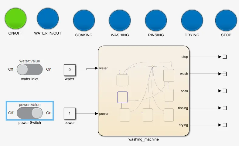
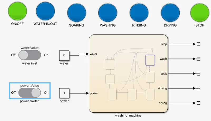
- POWER IS ON WATER INLET IS OFF :When power is on but the water inlet is off condition so, this mode satisfies the given condition at the situation the machine is in stop position.
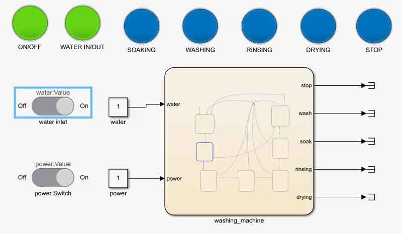
- WATER INLET IS ON : This mode the water inlet switch is operates OFF to ON position we can observe the LED position.
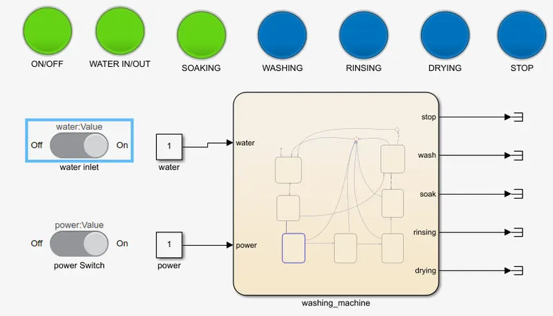
- SOAKING : This mode is activated when water is filling.
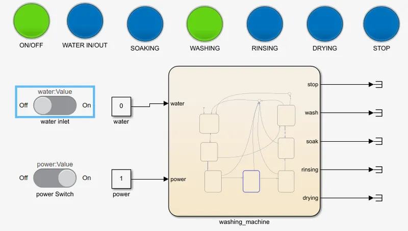
- WASHING : This mode we operate water inlet switch ON to OFF mode. After soaking delay time 200s is completed, then washing process is start. we can observe the LED which process is running.
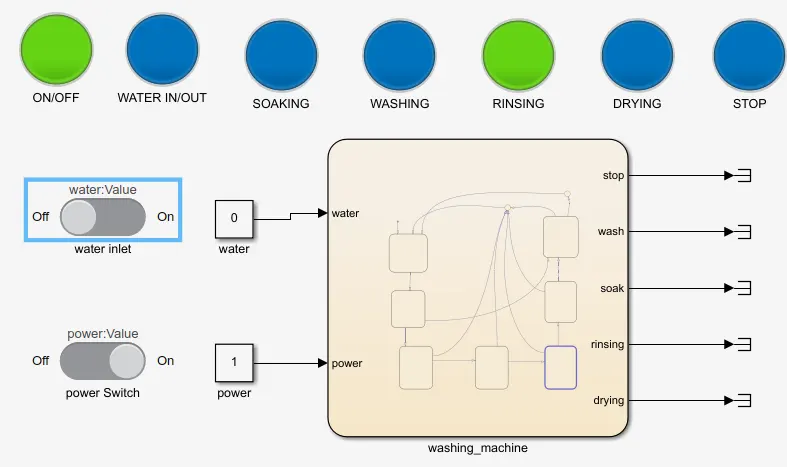
- RINSING :After completing the process time of 100sec of washing. Then immediatly start rinsing and we observe the LED indication.
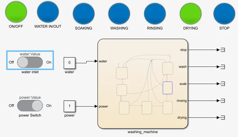
- DRYING :After completing the process time of 20sec of rinsiong. Then immediatly start drying and run 50 sec we observe the LED indication.
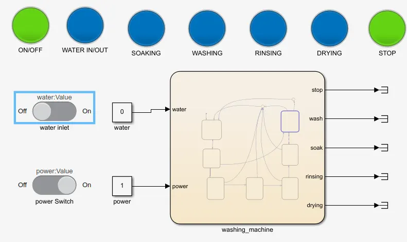
- STOP/FINISH :After completing the process time of 50sec of drying. Then immediatly stop the process/ finish and we observe the LED indication.
- Again this proces to start remove all the dry cloths in the washing machine. and operate water inlet switch.
MISSING LOGICS: The inlet water switch is operation is deficut to control. i think a relay and adition control system to be operated automatic process of washing machine.
I'm trying to make fully automatic process of original washing machine point of view
RESULT: Hence, the implementation of 'washing machine' program and its simulation process is completed satisfactory, And knowing of how to use stateflow chat and logic implementation.
QUESTION 2:
2. Make a Simulink chart for the “Gear shift” logic as per below conditions:
Speed Range(kmph) Gear
0 to 15 1
16 to 25 2
26 to 40 3
41 to 60 4
Above 61 5
Give speed input while the simulation is running & display the gear number.
AIM: To implemant a ''GEAR SHIFT'' logic using given conditions.
WORKING: Shifting of gears is a mechanical movements for increasing or decreasing of the speed. Initially a body have potential energy some foreces are acting on it like inertia. to eleminate that much amout of inertia low speed motions and high torques are provide. The vehicle speed is also changed with the help of the transmission keeping the engine speed the same with a certain limit. so, gears shiftings are uesd for different gear ratios.
REPRESENTATION OF BLOCKS:
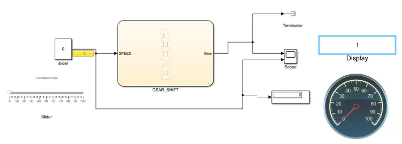
- SLIDER: It is a virtual element used for changing the values in simulation running time.
- CONSTANT: This block is uesd for assigning for input port of the stateflow chart.
- SCOPE:Used for observing the plots of obtained output.
- DISPLAY:This block is used for displaying the values
- TERMINATOR: This is used for terminating the program.
- VIRTUAL DISPLAY:The name virtual mean without physical connection is appear. this display connets internally.
- VIRTUAL CIRCULAR METRE: it is gauge or metre used for observing the different kinds of value of its ranges.
CHART:
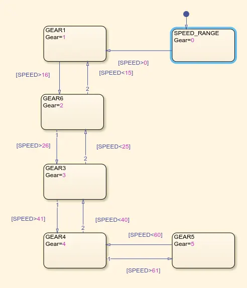
BASIC PROCESS: Above stateflow chart represents the given speed range and its gear positions.
the speed range is 0 to 15 it runs gear position 1. greater than 15 it shifts to gear 2. the speed range is 16 to 25 it runs gear position 2. greater than 25 it shifts to gear 3.the speed range is 26 to 40 it runs gear position 3. greater than 40 it shifts to gear 4. the speed range is 41 to 60 it runs gear position 4. greater than 61 it shifts to gear 5.
ASSIGNING OF INPUTS AND OUTPUTS:
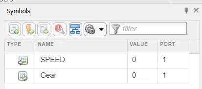
PROCEDURE STEP BY STEP: Initially the simulation stop time is change in to infinity (inf). click the run button of the simulation.
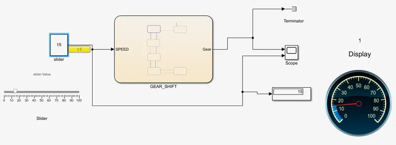
- GEAR 1 : If we change the slider values 0 to lessthan 15 the virtual display shows position of gear 1 and virtual gauge shows speed range. here i raise exactly 15 kmph.
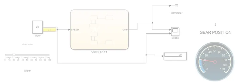
- GEAR 2 :If we change the slider values increase above 15 the virtual display shows position of gear 2 and virtual gauge shows speed range 20kmph.
- GEAR 3 :If we change the slider values increase above 25 the virtual display shows position of gear 3 and virtual gauge shows speed range 32.92kmph.
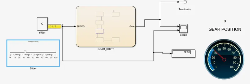
- GEAR 4 :If we change the slider values increase above 41 the virtual display shows position of gear 3 and virtual gauge shows speed range 50.65kmph.
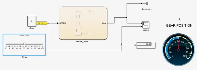
- GEAR 5 :If we change the slider values increase above 61 the virtual display shows position of gear 5 and virtual gauge shows speed range 69.4kmph.
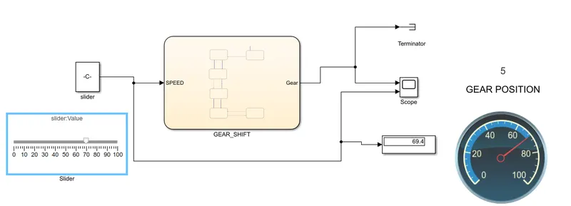
GRAPHS: Gear positions with respect to speed range.
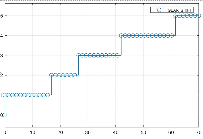
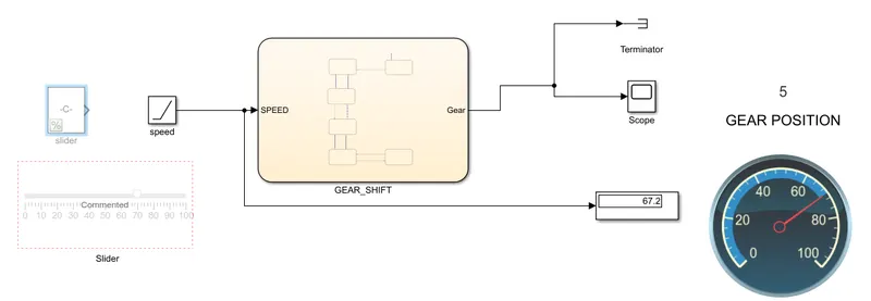
ADDITIONAL: here i use a ramp block how the gear shifting works by using this block.
only for observtion purpose.
- USING RAMP BLOCK:
- GRAPH:
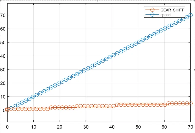
RESULT: Hence the gear shift experiment and observing their graphs, displays, gauges and slider position.
the stateflow implementation of gear shift with respects to their speed renge.