Project
SIMULATION OF A BAJA ALL TERRAIN VEHICLE (AVT) USING CONTINUOUS VARIABLE TRANSMISSION (CVT)
AIM:- To run and observe the simulation of BAJA All Terrain Vehicle (AVT) by using Continuous Variable Transmission CVT.
~ To Simulate the AVT by CVT model without closed loop of vehicle velocity and it's dashboard.
~ To Simulate the AVT by CVT model dashboard using vehicle velocity loop
OBJECTIVE:-
To Study and make a report on AVT with their respective images.
To run the simulation of AVT by using CVT make to change the valuse and observe the results.
THESIS:- Baja all terrain vehicle is to design a four wheel vehicle sustainable for any road condition for any simple event based useful for travel a short or medium distances. Considering all condition like Reliability, Sustainability, Safety, vehicle efficiency,
BAJA ALL TERRAIN VEHICLE (AVT)
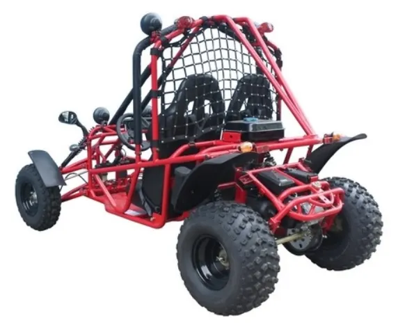
Physical components:
Vehical Body
2. Engine
3. continous variable transmission
4. wheel
5. suspension
REPRESENTATION OF BLOCKS IN SIMULINK:
1. Generic Engine.
2. Continuous Variable Transmission CVT.
3. Simple Gear.
4. Vehical Body and.
5. Other simulink blocks.
1. Generic Engine: The Generic Engine block represents a general internal combustion engine. This block is a suitable generic engine for spark-ignition and diesel. Speed-power and speed-torque parameterizations are provided. A throttle physical signal input specifies the normalized engine torque.
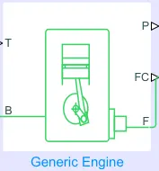
The throttle input signal T lies between zero and one and specifies the torque demanded from the engine as a fraction of the maximum possible torque. If the engine speed falls below the Stall speed, the engine torque is blended to zero. If the engine speed exceeds the Maximum speed, the simulation stops and issues an error message.
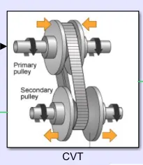
2. Continuous Variable Transmission CVT: It also known as pully belt drive transmission, shiftless transmission. there is no gear system, a belt is connected in between 2 pullys one is outward means more space to belt track and another one is inward means narrow space to belt track also friction provider.
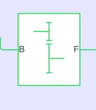
3. Simple Gear: This gear is connected to cvt and eingne with a simple gear ratio for engine speed reduction.
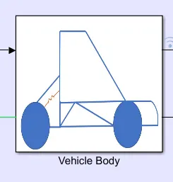
4. Vehical Body and: A metalic regied body is design to include wheels, suspension, metal frames etc
5. Other simulink blocks:
5.1 Signal Builder used for develop required signal to given input parameters
5.2 Scope is used for observing the model dynamics in the form of graphs or plots.
5.3 Solver Configuration function used for program solve purpose which are inbuilt equations in blocks.etc
WORK 1:-
MODEL 1:- SIMULINK MODEL OF BAJA ATV WITH CVT
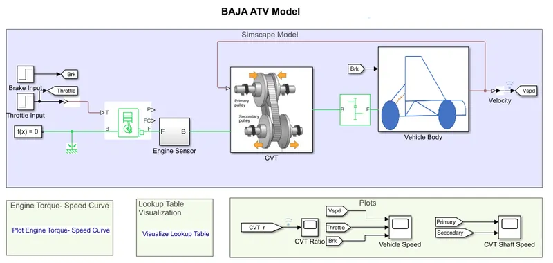
Baja All Terrain Vehicle with Continouse Variable Transmission by providing some input values with the help of signal builder. a signal is design in the signal builder map. Throttle is connected to engine block, Input Break is connected to vehicle body.
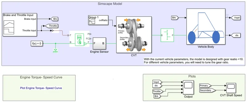
Signal Builder:- Signal builder used for develop required signal input to generic engine that is throttle
The throttle value is shown above graph.
Gneric engine: Represents a system-level model of spark-ignition and diesel engines suitable for use at initial stages of modeling when only the basic parameters are available. Optional idle speed and red line controllers are included.
The throttle input signal T lies between zero and one and specifies the torque demanded from the engine as a fraction of the maximum possible torque. If the engine speed falls below the Stall speed, the engine torque is blended to zero. If the engine speed exceeds the Maximum speed, the simulation stops and issues an error message.
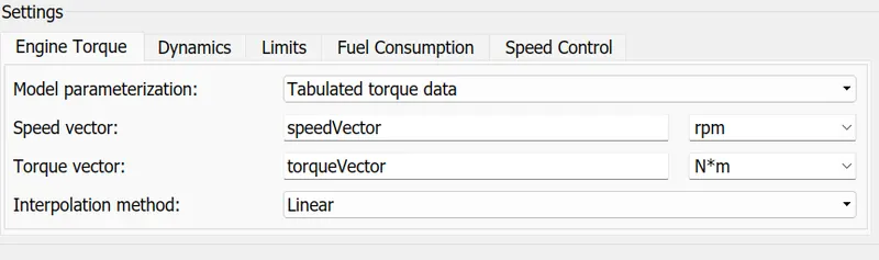
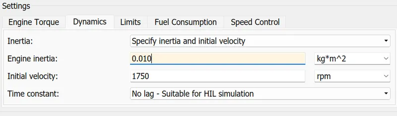
parameters of generic engine:
Excel format:
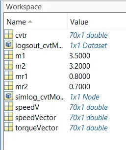
Speed vectors and Torque vectors are already assing in matlab workspace excel
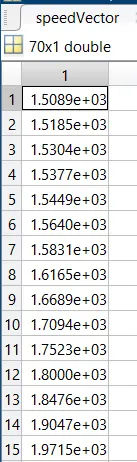
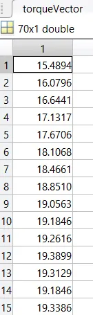
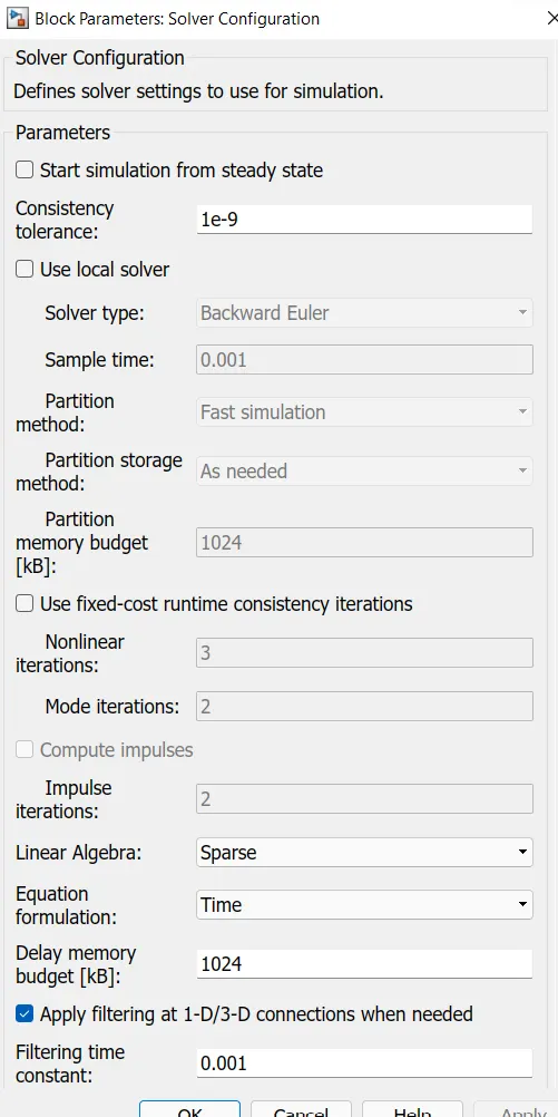
Solver Confeguration: this block use for solving mathamatical operation at back end.
Engine sensor:
Engine sensor is connected to a generic engine and CVT. It has mechanical rotational sensor and their similar blocks
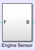 This sensor measured in between two mechanical rotational nodes.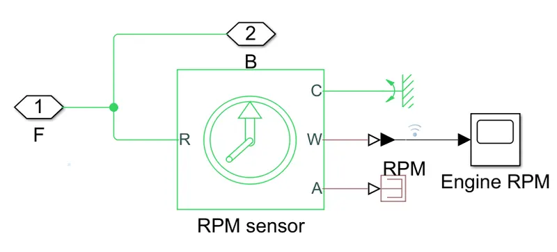
The physical signal ports W and A report the angular velocity and angle, respectively, of port R relative to port C. The measured angular velocity is positive when the angular velocity at port R is greater than the angular velocity at port C.
Continuous Variable Transmission CVT:
-- Primary pully
-- Secondary pully
-- Belt
if variator of a primary pully outwards and secondary pully goes inwards it will leads to speed reduction.
if variator of a primary pully inwards and secondary pully goes outwards it will leads to over drive.
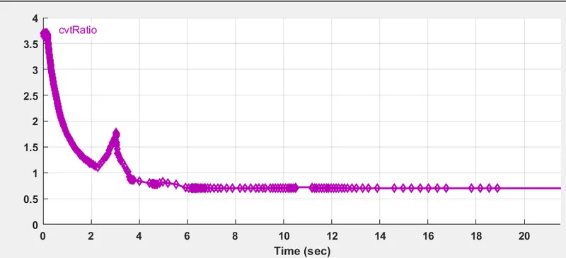
CVT Ratio:
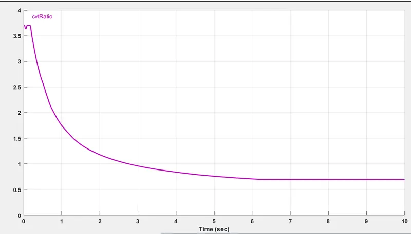
A CVT subsystem have input/output shaft inertias, variable gear ratio and rotational sensors.
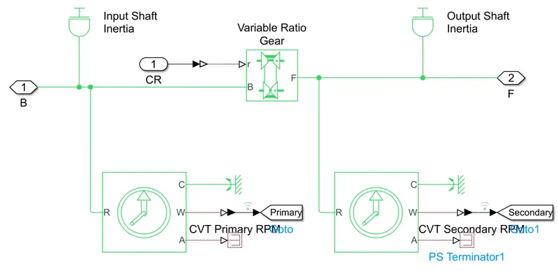
Vriable Gear Ratio: Represents a variable ratio gearbox such as implemented by mechanical belt CVT, electric, or hydraulic transmissions. The physical signal input r defines the ratio of input to output angular shaft velocities.
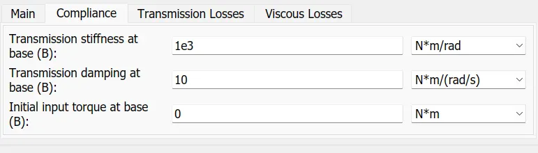
Simple Gear: It is used for speed reduction.
Connections B (base) and F (follower) are mechanical rotational conserving ports. Specify the relation between base and follower rotation directions with the Output shaft rotates parameter. Optionally include thermal effects and expose thermal conserving port H by setting Friction model to a temperature-dependent setting.
Vehical Body: It represents a two axle vehical body. it inludes break drum, real wheels,suspension, engine, front wheels also some physical systems. also some important peramaters that are mass, gravity, air dynamics, friction, leveling and condition of road.
In vehicle body block NR, NF, W, V, H also beta are speed rear, speed front, wind velocity, velocity, head also inclination respectively.
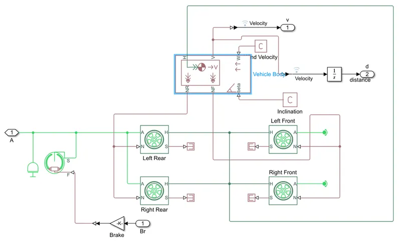
Perameters of vehical body:
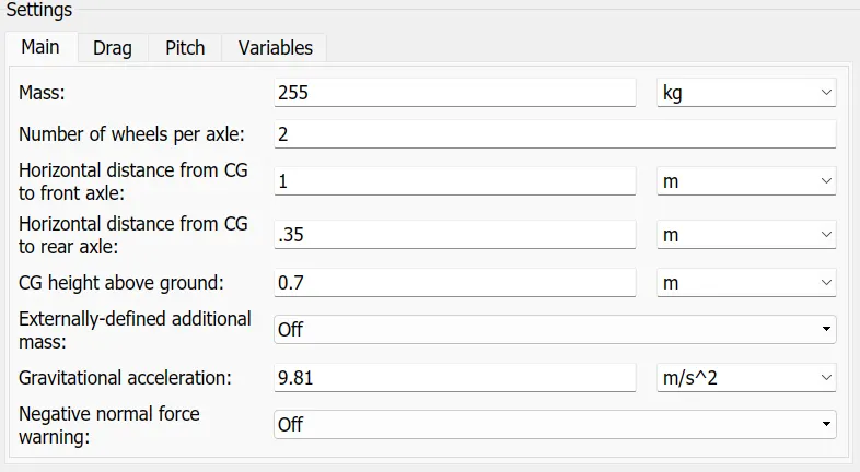
above all these perameters are employed on the vehicle that means mass, gravity, weight, height, length and force etc.
Break Drum: Represents a brake arranged as two pivoted rigid shoes symmetrically installed inside or outside a drum and operated by one actuator. The actuator force causes the shoes to exert a friction torque on a shaft connected to the drum.
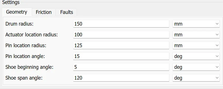
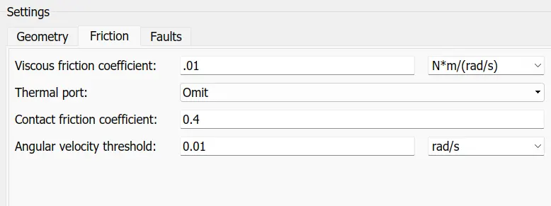
MODEL 2:-SIMULINK MODEL OF BAJA ATV WITH CVT DASHBOARD
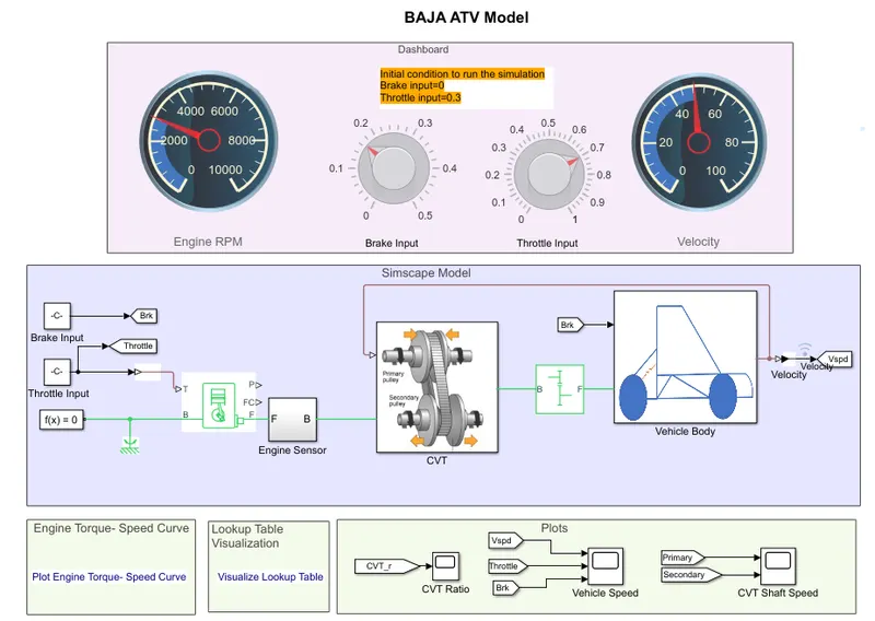
In this model A Dashboard is provide to examine the valuse which are provide by the rotary nobe during simulation is running. The simulation stop time is infinte and normal mode operation.
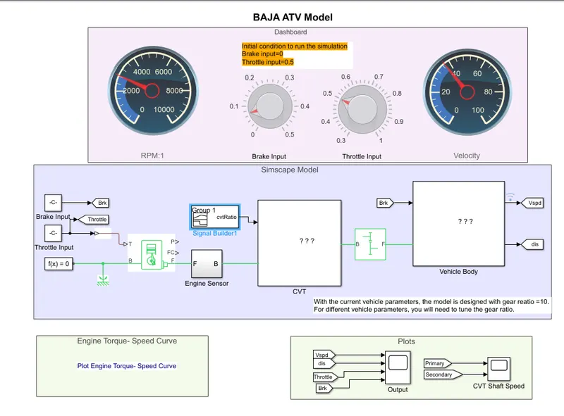
Here 2 constant block are interlink to rotary nobe that are assing the name like break, throttle inputes also,
2 meter gauges are connected with RPM and Velocity for check the engine and cvt performance of the vehicle.
CVT RATIO:
WORK 2:-
MODEL 1:-SIMULINK MODEL OF BAJA ATV WITH CVT RATIO LOOKUP TABLE.
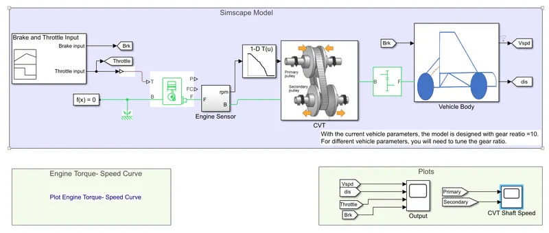
In this model a signal block is removed i.e cvt ratio that are connected previously at continous variable transmission block at variable gear ratio. Now replace the signal builder with a block is used that is lookup table this block is employed in between engine sensor and cvt block.
INPUT VALUES
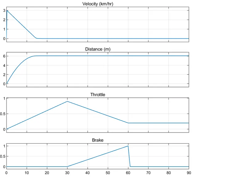
The above showing graph the throttle values are change in between 0 to 1 same as break input valuse.
when accellarating time the break is 0 position upto 30 sec and deaccelarating time the break valuse reaches the point 1 at 60sec.
Lookup table:
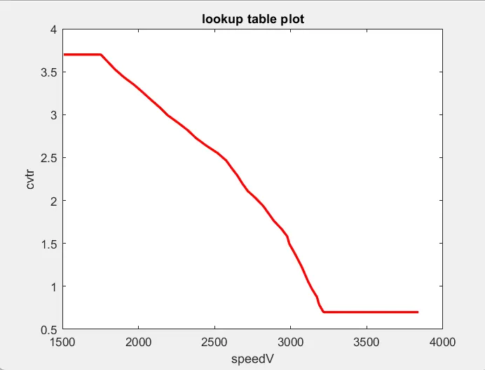
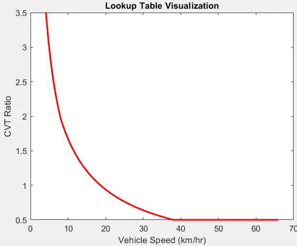
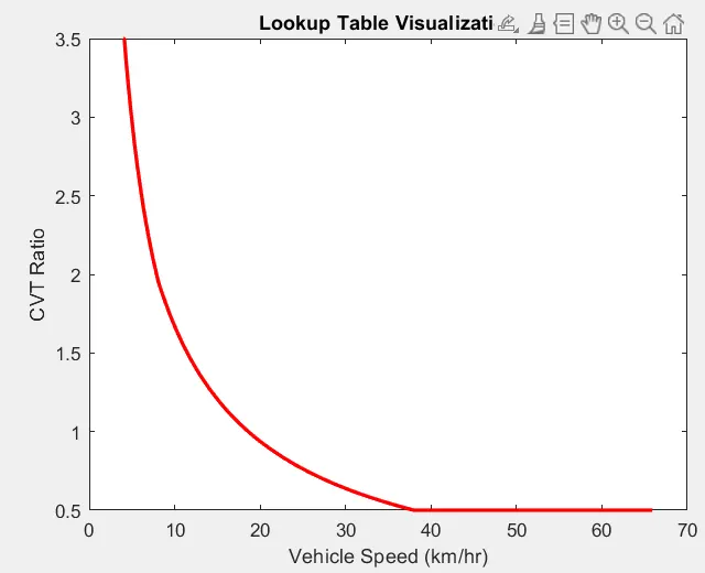
the Lookup Tables library to model nonlinearity. Lookup table blocks use arrays of data to map input values to output values, approximating mathematical functions. To approximate a function in N variables. it is a Approximate one-dimensional function. This lookup table plot a graph in between cvtratio on y axis, speedV on x axis.
WORKSPACE:
MODEL 2:-SIMULINK MODEL OF BAJA ATV WITH CVT MAPPED (closed loop)
In this model the vehicle velocity is connected to the lookup table block and the output os this block is connected to the cvt variable gear ratio block. The lookup table graph is plot in between vehicle speed km/hr, cvt ratio.
A CVT has input primary shaft and output secondery shaft respectively input and output inertias.
Vehicle RPM:
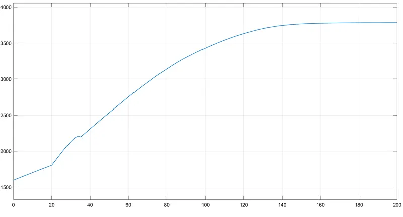
When the engine sensor or RPM sensor sense the speed of the engine that are running by the input values of throttle input.
the graph is lies in between of time and rpm x axis and y axis respectively.
CVT Ratio:
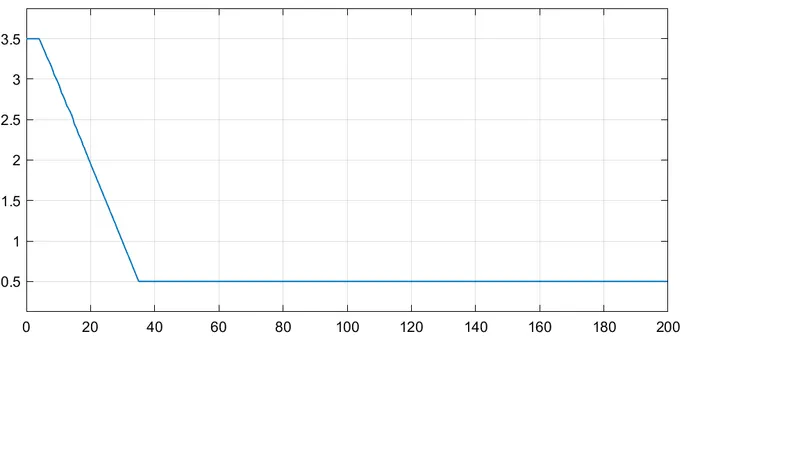
This ratio is taken at the lookup table at cvt block. the cvt ratio means the difference betwween input and output of the vehicle.
MODEL 3:-SIMULINK MODEL OF BAJA ATV WITH CVT MAPPED DASHBOARD
In this model a dashboard is shows engine rpm, break applied input, throttle input, vehicle velocity.
Initilly all the perameters of throttle and break is zero position. also, simulation time is set infinite or 600sec. first apply some throttle input value something 0.3 run and pass the simulation, again applie throttle value 0.7 run and pass the simulation. now the engine rpm shows 4000 rpm and vehicle velocity shows 70km/hr.
now apply some amount of brake input 0.35 value run the simulation and pass. a major change is occure in the engine rpm and vehicle velocity that tha values is 3000rpm and 50km/hr speed.
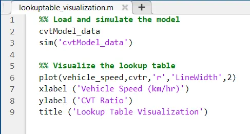
Make a program at command window in matlab or open already program that is related to lookup table visualization.
a plot is draw in between vehicle speed and cvt ratio.
COMMAND WINDOW PROGRAM & WORKSPACE:
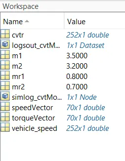
In workspace we can observe some tables that are cvtr, vehicle speed, speed and torque these are excel formate data click the anyone sheet it will show the data and save the data in desired folder.
RESULT:
ENGINE TORQUE _ SPEED CURVE:
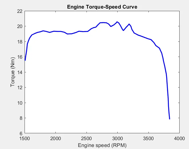
A plot is drawn in between engine speed (rpm) and torque (nm) x-axis and y-axis these values are taken from vehicle engine of atv. the engine speed from 0 to 4000 rpm and torque values are from 0 to 22+.
WORK 1:-
MODEL 1:-SIMULINK MODEL OF BAJA ATV WITH CVT
INPUTS AND OUTPUTS:

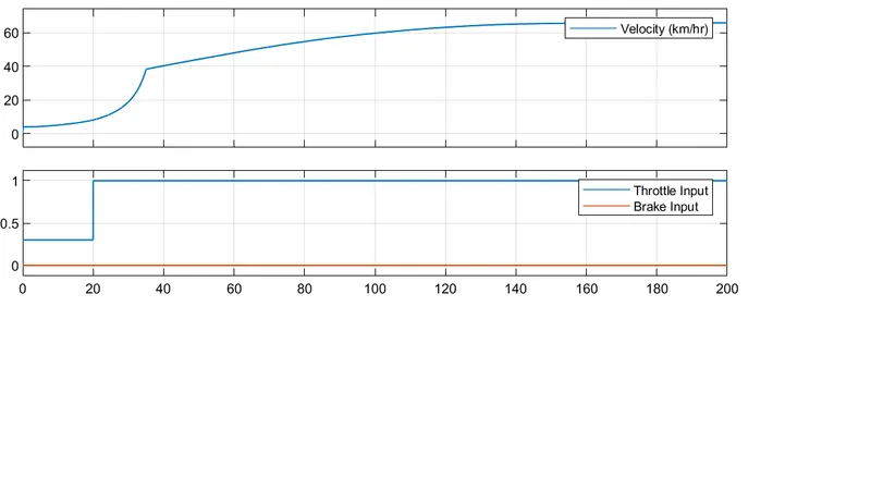
As per the given input values of brake and throttle values of above shown in the graph. I observe the values of vehicle velocity and distance travelled.
RPM VALUES:
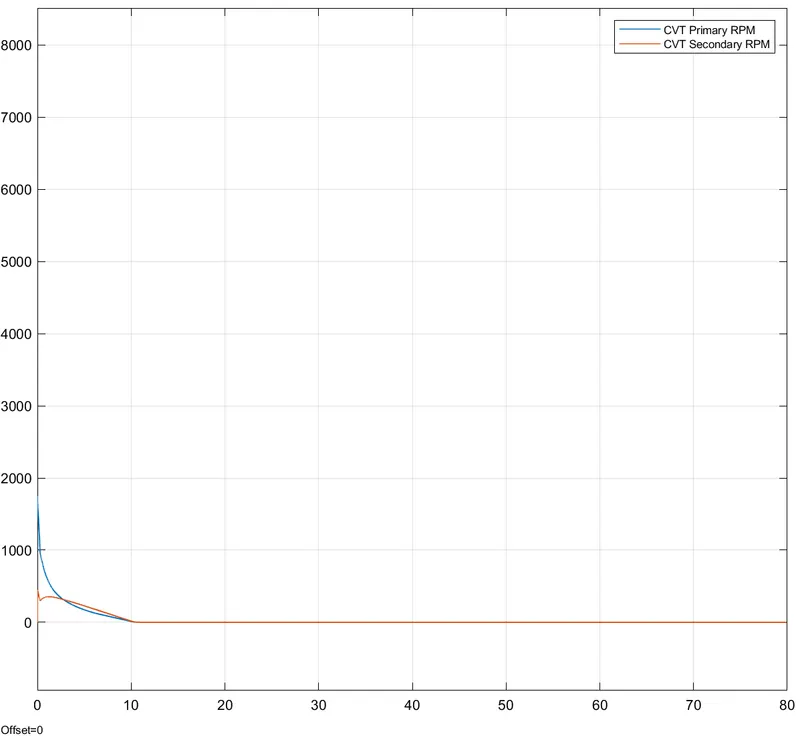
A Variable Ratio Gear is the main block it has 2 inputs primary shaft and secondary shaft. The primary shaft is connected to engine sensor and secondary shimple gear system. 2 rpm sensor are connected at primary and secondary of the variable ratio gear. The above shown graph is the data of primary and secondary.
MODEL 2:-SIMULINK MODEL OF BAJA ATV WITH CVT DASHBOARD
CVT Ratio of the cvt dashboard
output 1:INPUTS AND OUTPUTS:
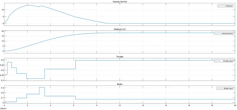
similarly same as the model of cvt model a dashboard is represent in this model. in the dash board we know a throttle nobe brake nobe is operated when simulation time.
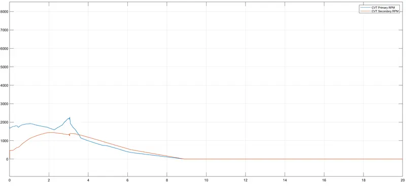
output 2: RPM VALUES:
primary and secondary shaft data.
WORK 2:-
MODEL 1:-SIMULINK MODEL OF BAJA ATV WITH CVT RATIO LOOKUP TABLE.
In this model i change some values also i build a signal in signal builder with respect to time. The throttle is set from 0 to 1 values. also brake is similar values.
INPUTS AND OUTPUTS:
RPM VALUES:
Here the velocity is suddenly increased and falls slowely,
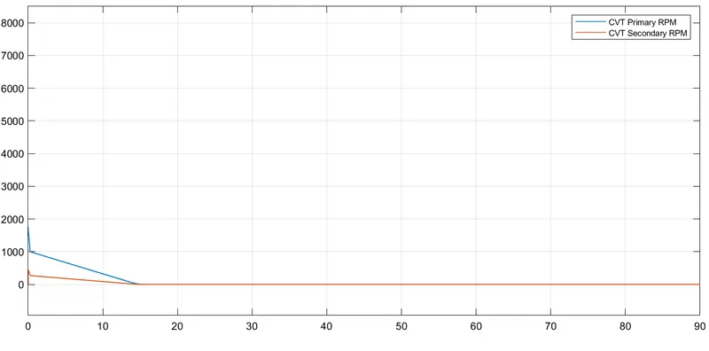
CVT primary and secondary rpm's of variable ratio gear.
MODEL 2:-SIMULINK MODEL OF BAJA ATV WITH CVT MAPPED (closed loop)
Here in this model the vehicle veloity that means vehicle speed is connected to lookup table and mention in the form of vechile speed (km/hr) that is assigned by input x. A excel values is taken from matlab that is CVT Ratio assigned by input y.
observe the result in the below fig.
A Step signal is defined as a input throttle value 0.3 the time intervel of 0 to 20sec after 20 sec throttle value is 1.
maintain the brake value is constant that means 0.
INPUTS AND OUTPUTS:
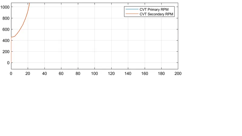
observe the graph of primary and secondary. here secondary cvt rpm is suddenly increase o to above 400 at 0 instant. after above 400 rpm is change to above 1000 with a time instant is 0 to 21 sec.
RPM VALUES:
MODEL 3:-SIMULINK MODEL OF BAJA ATV WITH CVT MAPPED DASHBOARD
Here i observe the chnages of velocity and distance of the avt vehicle by chnageing the values of throttle node and brake respectively.
INPUTS AND OUTPUTS:
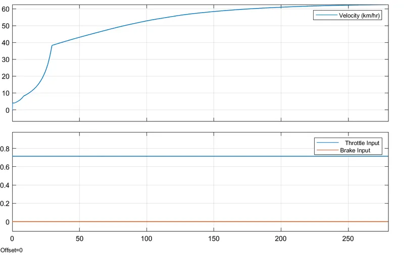
In the above mentioned graph shows the blue line i.e throttle value is run at 0.7 at that time the break is not applied.
then the vehilce velosity is change to increased 40 to 60+ range rpm. simulation time is 300sec
INPUTS AND OUTPUTS:
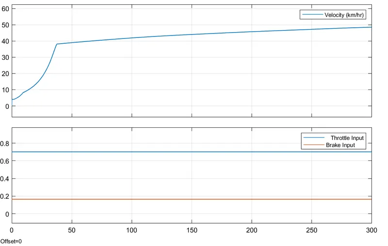
here i observe the graph to applied a constant brake 0.18 with a conatant throttle is same as before values i.e is 0.7.
then this point the vehicle velocity and rpm is decreased to 60+ to 49 rpm with a simulation time is 300sec
RPM VALUES:
here the secondary value is raaises suddenly up to 400+ at 0 instant. a slight change is occures at above 450 also time inatants are change from 0 to 20sec.
CONCLUSION: Hence all the results of baja all terrain vehicle model by simulation is done by some special modes that is signal builder, step inputs, lookup tables, dashboards and closed loop for lookup table.
I examin the values to change some values like engine, simple gear ratios, signal builder's signal structure etc.
Knowing some more blocks and it's new features. Building a program and it's simulation.
My openion: At the time of taking this challange i don't know how to present this project, knowing about this project 'what is what'.
thank you....