Week -2
QUESTION 1: Make a Simulink model of Doorbell using solenoid block.
AIM: To make a simulink model of doorbell using solenoid block.
Given structure.
Working: DOORBELL is a electromagatic device which makes the sounds by using electrical currents and alloy bell. A bell point hits continously to the bell by the magnatic forces of solenoid plunger when currents are passed through the solenoid coil with the help of battery or other electrical source.
The Schematic representation of blocks:
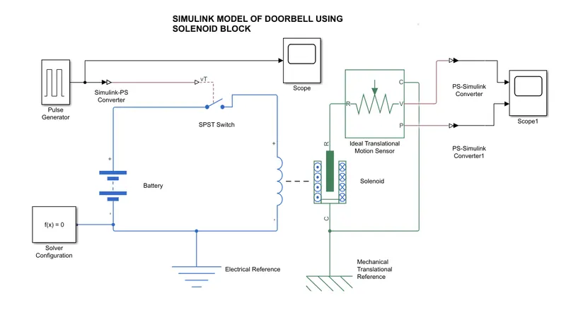
COLOUR INDICATIONS:
BLUE : ELECTRICAL BLOCKS
BLACK : COMMONALY USED BLOCKS
GREEN : MECHANICAL BLOCKS
USED BLOCKS:
- Pulse generator: The Pulse Generator block generates square wave pulses at regular intervals. The block waveform parameters, Amplitude, Pulse Width, Period, and Phase delay, determine the shape of the output waveform.
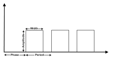
- Solver configuration: The Solver Configuration block specifies the solver parameters that your model needs before you can begin simulation. for any physical network or block.
- simulink-ps conv: The unit expression in 'Input signal unit' parameter is associated with the Simulink input signal and determines the unit assigned to the Physical Signal
- Battery: The battery model block is same as a bettery symbol.
- SPST Switch: The block represents a Single-Pole Single-Throw (SPST) switch controlled by an external control signal vT. If vT is greater than the threshold, then the switch is closed, otherwise the switch is open.
- Scope: it used for observing the output plots of the systems.
- Solenoid: The Solenoid block represents the electrical characteristics and generated force for the solenoid in the following figure:
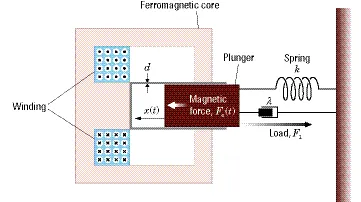
The return spring is optional. To remove the effects of this spring from the model, set the Spring constant parameter to
0.To show the direction in which the solenoid acts, the block icon changes dynamically based on value of the Motion direction under excitation parameter. -
Translational Motion sensor: the sensor measure between the two mechanical translation nodes into a control signal proportional to velocity or position.
- mechanical reference
- electrical reference
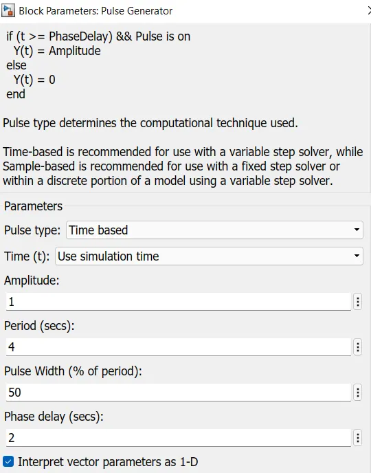
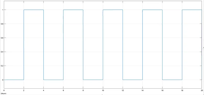
PULSE GENERATOR:
PROCEDURE:
Arrange all the blockes in order to connection.
set the simulation time 20seconds
edit pulse generator parameters like amplitude, time period, width, phasee delay, 1, 4, 50, 2 respectively. this signal is given to the spst switch set threshold value is 0.5v of the switch. connect the battery inseries with the switch voltage 50v, internal resistance is 0.01ohm.
connect the solenoid (+.-) terminal to the switch and ground respectively. and change the values of the solenoid like voltage, current, force, mass, position etc. connect the ideal translation motion sensor to the R terminal and we observe the output at the scope by using the ps to simulink converter.
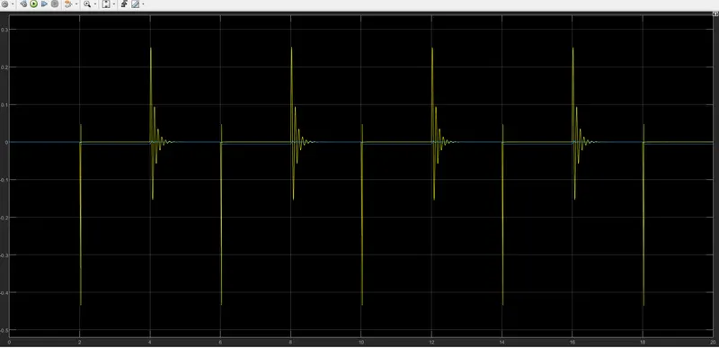
OUTPUT RESULT:
CONCLUSION:
I observe each and every step to know how to use every block.
By changing the values of function generator, spst switch, solenoid and motion sensor the outputs of graphs from scopes are effected.
Finally i conclude the graph of the output is not get satisfactorly because in the given question the switch is close 2 seconds that means the bell is also rings 2 seconds but, here it is not.
QUESTION 2: Use a thermistor to sense the temperature of a heater & turn on or turn off the fan
AIM:Use a thermistor to sense the temperature of a heater & turn on or turn off the fan
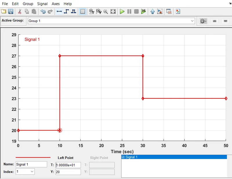
CONDITION:Temperature source: 20 °C from 0 to 10 seconds, 27 °C from 10 to 30 seconds, 23 °C from 30 to 50 seconds
Fan conditions: ON if the temperature above 25 °C, OFF otherwise
WORKING: Thermistor is a temperature sensing device it has a bimetalic trip that is a combination of metals these are sensiable to the heat. when this thermister experence the external heat or current drift inside the metal, the matal tips are expands or directly disconnect the supply. the whole process are depends on heating elements of the system like fan, iron, geasor, a/c etc.
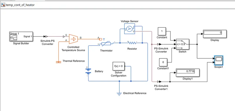
The Schematic representation of blocks:
COLOUR INDICATIONS:
BLUE : ELECTRICAL BLOCKS
BLACK : COMMONALY USED BLOCKS
ORANGE: THERMAL BLOCKS
USED BLOCKS:
- CONTROLLED TEMPERATURE SOURCE: This block used for controling the temperature signal from external source with reference and the signaled output is taken at B.
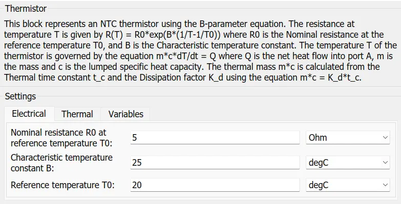
- THERMISTOR:
- BATTERY: It is a Electrical Source to supply power to the heater through thermistor. voltage 50v, internal resistance 2ohm.
- RESISTOR or HEATER: which consumes electrical current to produce heat or which opposes the flow of current.
- VOLTAGE SENSOR: a sensor or meter is used to detects the potential difference in parallel of the element or device.
- DISPLAY: This for displaying the values visuavally.
- SCOPE:It is used for observing the performance of the system to analyse the plots on graphs.
- SIGNAL BUILDER: It is a signal building system to built the signal by manual adjustments and giving some values.
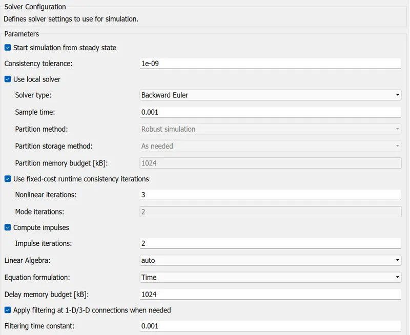
- SOLVER CONFIGURATION: Every physical system to solved by some other equations in the program.
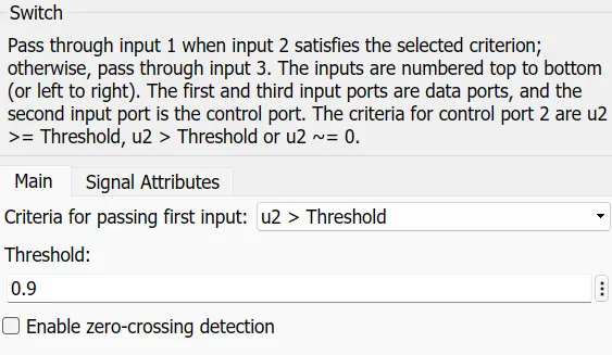
- SWITCH: It is a device works under boolen operation 0 or 1, when the input is below the threshold value the out put is low otherwise high.
PROCEDURE: Arrange the blocks in a manner to provide perfection. A signal builder block to built a signal required level Temperature source: 20 °C from 0 to 10 seconds, 27 °C from 10 to 30 seconds, 23 °C from 30 to 50 seconds. The out of signal builder is connected to the temparature source through simulink to ps converter set value 1.
The temperature source is a source provider to the thermister port A through point B with thermal reference point A.
A Battery source voltage 50v, thermistor R0 at T0 reisitance is 5 ohm,constant temperature T0 is 25 degrees, reference temperature is 20 degrees, resistor or heater resistance is 12 kohm, these are connected in series.
A voltage sensor is connected accross the heater measures the potential difference. the output v of the sensor is connect to the switch through ps to simulink converter.
the switch has 3 input terminals top and bottom are for switching reference like 1,0 and middle is for threshold 0.9. output terminal of switch is connected to the display and scope.
A display and scope is connected to voltage sensor through ps-simulink converter for knowing what value is obtained at heater, the value is 0.7716.
RESULT:
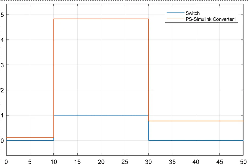
CONCLUSION: The value of voltage sensor is 0.7716, The switch threshold value is 0.9.
so, ON if the temperature above 25 °C, OFF otherwise
sensor value 0.7716< threshold 0.9 this means the value is low so, the fan is off at below values of temprature.