Week - 4
Question No.:01
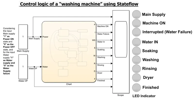
Implement control logic of a “washing machine” using Stateflow
Conditions:
- If the power supply is available, the system gets activated,
- If the Water supply is not available, stop the process & indicate through the LED,
- Soaking time should be 200sec. followed by a Washing time of 100sec.,
- Then rinsing happens for the next 20sec. & dryer runs for 50sec. and
- After all the processes have been completed turn on the finished LED.
Symbols:
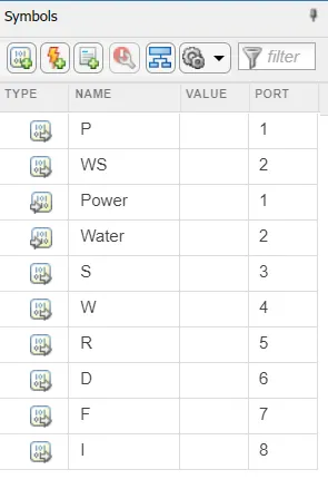
Symbol assigned - i."Power" (I/P Power supply), and ii."Water"(I/P Water Supply) is the input data & i."P"(Machine ON), ii."WS"(Water Supply to the M/c.), iii."S"(Soaking), iv."W"(Washing), v."R"(Rinsing), vi." D"(Dryer), vii, "F"(Finished), and viii." I"(Interrupted-Water failure) is the output data.
Stateflow/Chart:
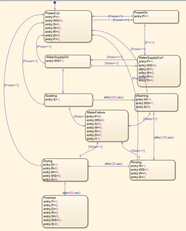
The above Stateflow chart shows the control logic for the washing machine.
A state describes the operating mode of the system. In a Stateflow chart, states are used for sequential design to create state transition diagrams.
States can be active or inactive. The activity or inactivity of a state can change depending on events and conditions.
A transition is a line with an arrowhead that links one graphical object to another. In most cases, a transition represents the passage of the system from one state to another.
A transition typically connects a source and a destination object. The source object is where the transition begins and the destination object is where the transition ends.
The Label in the transition describes the condition/state of the transition
In this chart, the "Execution Order" is the most important factor to prioritize for the execution of a transition during simulation.
Let us consider the input for Main supply "1" as the Power ON state and "0" as the Power OFF state for the Washing Machine, and
the input Water supply "1" as the Water supply and "0" as the Water Supply failure for the washing machine.
So, As per the condition, the power supply is required to activate or start the machine. The water supply is required from soaking operation to rinsing operation (for dryer operation, the water supply should be cut off.)
and if any interruption of water supply between the operations, the machine should stop the cycle and indicate via lamp "Inertrupted (Water Failure)".
For each operation, a separate lamp is assigned for the machine operation condition indication.
Scope output shows one complete cycle of the control circuit operation:
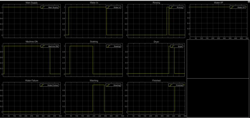
[For our sequence, (without interruption) approximately 410Sec. required to complete one cycle of operation]
-------------------------------------------------------------------------------------------------------------------------------------------------------------
Question:02
Make a Simulink chart for the “Gear shift” logic as per below conditions:
Speed Range(kmph) Gear
0 to 15 1
16 to 25 2
26 to 40 3
41 to 60 4
Above 61 5
Note: Give speed input while the simulation is running & display the gear number.
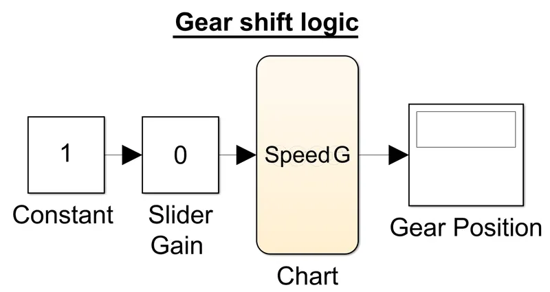
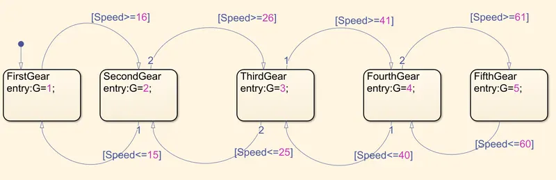
State Flow/Chart:
The Slider Gain block performs a scalar gain that you can modify during simulation. In this model, slider gain is going to act as an accelerator of our vehicle.
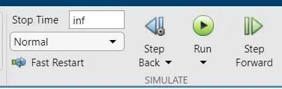
As shown in the above image, we need to set the Stop Time as "inf". So, the simulation runs the program until you explicitly pause or stop it.
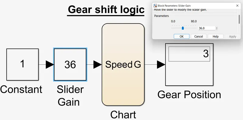
As shown in the above image the "Gear Position" display shows the current gear position as per our speed reference/conditions.
----------------------------------------------------------------------------------------------------------------------------------------------------