Week -2
1. Make a Simulink model of Doorbell using a solenoid block.
Objective:
a. To create a Simulink model of Doorbell using solenoid block and,
b. To Observe the physical movement of the plunger.
a. To create a Simulink model of Doorbell using solenoid block and,
Simulink model of Doorbell using solenoid block
Like an electric doorbell, the solenoid coil also needs an electric signal to operate or function.
In this model, we are considering the solenoid coil as a bell and is used for the mechanical movement/displacement.
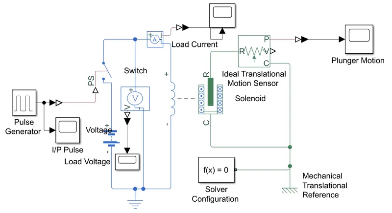
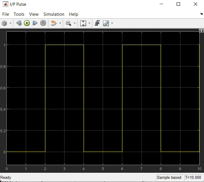
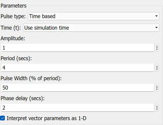
The pulse generator is used to trigger the switch with our programmed time delay and an ideal translational sensor is connected with solenoid block R to observe the plunger movement.
b. To Observe the physical movement of the plunger.
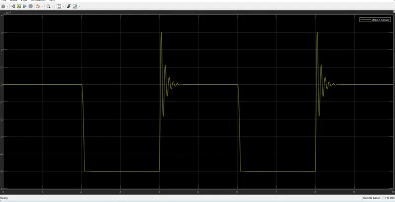
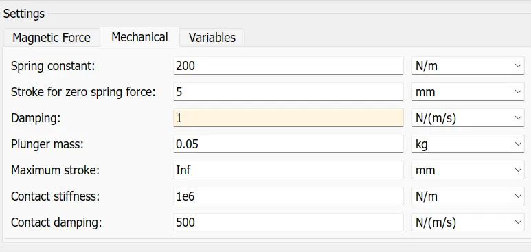
a. As shown in the above image the plunger has an oscillation at the end of each operation.
b. The oscillation in the plunger displacement depends on the mass of the plunger so it may control by increasing the damping value.
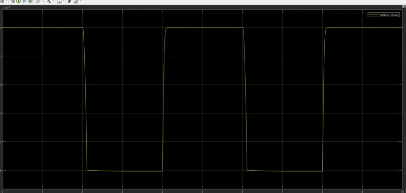
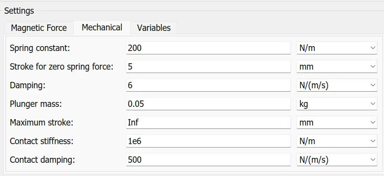
c. As shown in the above image, the displacement of the plunger has been fully controlled by increasing the damper value to 6.0N/(m/s).
---------------------------------------------------------------------------------------------------------------------------------------------------------
2. Use a thermistor to sense the temperature of a heater & turn on or turn off the fan as per the below conditions:
Objective:
a. To create a Simulink model to control the operation of the fan motor by using thermistor (Temperature based control) as per the below condition
Temperature : 20 °C from 0 to 10 seconds,
27 °C from 10 to 30 seconds,
23 °C from 30 to 50 seconds
Fan conditions: ON if the temperature is above 25 °C, OFF otherwise.
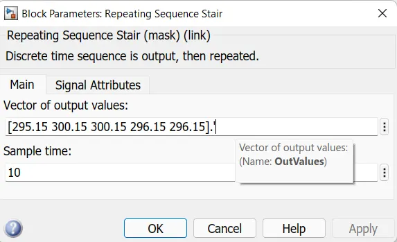
The following are the Input values to the ideal temperature source given by the signal generator.
Input Values:
- 20 °C or 293.15 Kelvin from 0 to 10 seconds,
- 27 °C or 300.15 Kelvin from 10 to 30 seconds, and
- 23 °C or 296.15 Kelvin from 30 to 50 seconds
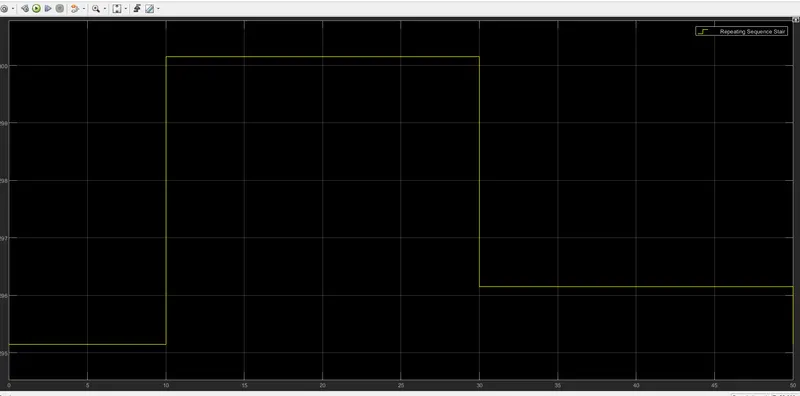
The Solenoid block is connected with the switch, battery, and other required blocks as per the image shown below and we will get a complete electrical circuit.
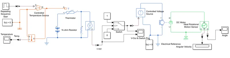
Fan controller Conditions (Temperature):
- For the above temperature 25 °C or 298.15 Kelvin, the fan should be ON.
- For below and equal to the temperature 25 °C or 298.15 Kelvin the fan should be in OFF condition.
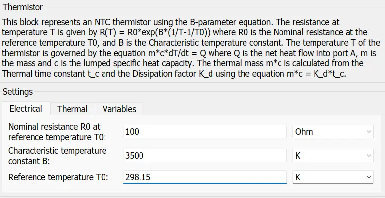
The above image shows the setting of Thermister (Negative Temperature Coefficient-NTC) and the reference resistor value is 1kilo ohm.
Note:
NTC thermistors are resistors with a negative temperature coefficient, which means that the resistance decreases with increasing temperature.
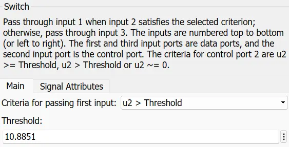
For our circuit, the output of the voltage sensor for the temperature reference at 25 °C or 298.15 Kelvin is 10.8850 so we need to set the threshold value as 10.8851 to get the high output[1] from the switch to match our conditions.
The below image shows the angular velocity output of the DC motor (Fan) and it is matches with our conditions.
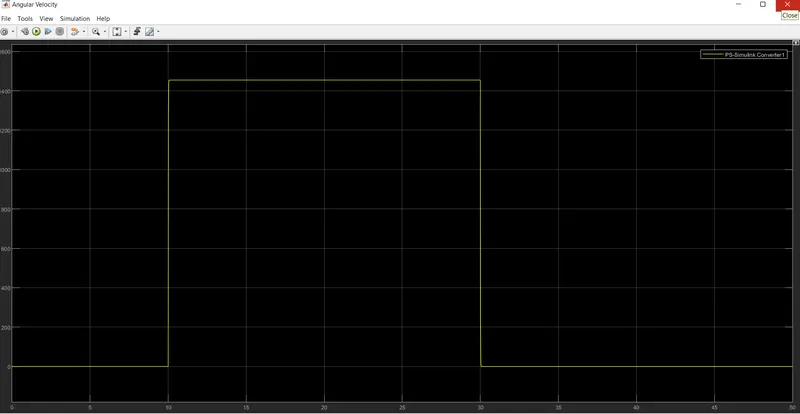
Fan ON / OFF Conditions:
- 20 °C from 0 to 10 seconds, (Fan Condition : OFF)
- 27 °C from 10 to 30 seconds, and (Fan Condition : ON)
- 23 °C from 30 to 50 seconds (Fan (Condition : OFF)
-----------------------------------------------------------------------------------------------------------------------------------------------------