Week - 4
1. Washing machine
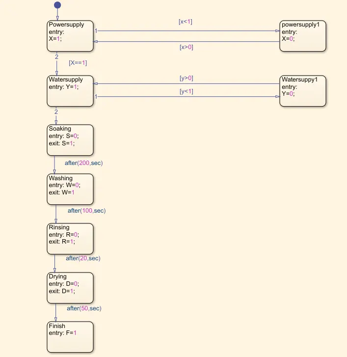
Aim: Implement control logic of a “washing machine” using Stateflow as per given sequence:
Conditions:
- If the power supply is available, the system gets activated
- If the Water supply is not available, stop the process & indicate through LED
- Soaking time should be 200s followed by Washing time of 100s.
- Then rinsing happens for the next 20s & dryer runs for 50s
Procedure:
Working Principle Of A Washing Machine: A washing machine by spinning at 800-1600 rpm helps soap and dirt with it to leave the surface of the cloth via centrifugal force and into outlet pipes. Hence utilizing centrifugation to both clean and partially dry the clothes loaded in it. Thus the processes are electrically controlled, such as the drum, valves, pump, motor and heating. The valve opens again and the dirty water drains out of the drums. The pump works to help get rid of the water. The valve lets clean water in again into the drums. The four processes are:
Soaking: it is used to dip clothes in detergent water to remove dirt from the clothes. In this function, customers need to select soak from a panel. Soak - This function is available with a wash timer. In 42 min of washing 27 min is soak and 15 min machine will wash the clothes.
Washing: During the wash cycle, a large plastic agitator(green) turns around, moving clothes through the water. When the washing is finished, the pump drains the water from the outer drum.
Rinsing: The dirty, soapy water is drained, then the washing machine is refilled and clothes are "rewashed" in clean water. Spin: All the water is drained completely, then clothes are spun very fast and excess water is removed due to centrifugal force.
Dryer: They work by pushing warm dry air through wet washing to extra moisture, then cooling the now humid air in a heat exchanger to condense the moisture, which is collected in a tank or pumped down the drain. Dry air is reheated and the cycle repeats.
State Flow: Systematic solution of a problem is possible with sequential, unambiguous and realizable finite process step set. This set is called "algorithm" and it is one of the most important parts of the programming languages. In the study, it is represented how to learn algorithms by using the Simulink State-Flow. Inflow diagram based algorithm learning.
Control Logic Of A Washing Machine: It checks for the extent of dirt and grease, the amount of soap and water to add, the direction of spin and so on. The machine rebalances the washing load to ensure correct spinning. Else, it reduces spinning speed if an imbalance is detected. Even distribution of washing load reduces spinning noise.
Control Unit:
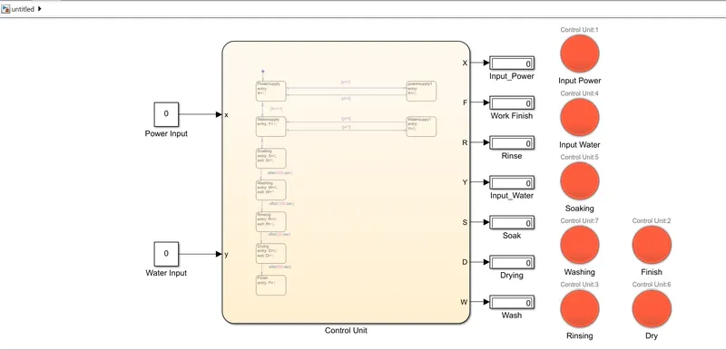
When both Power supply and Water supply is OFF:
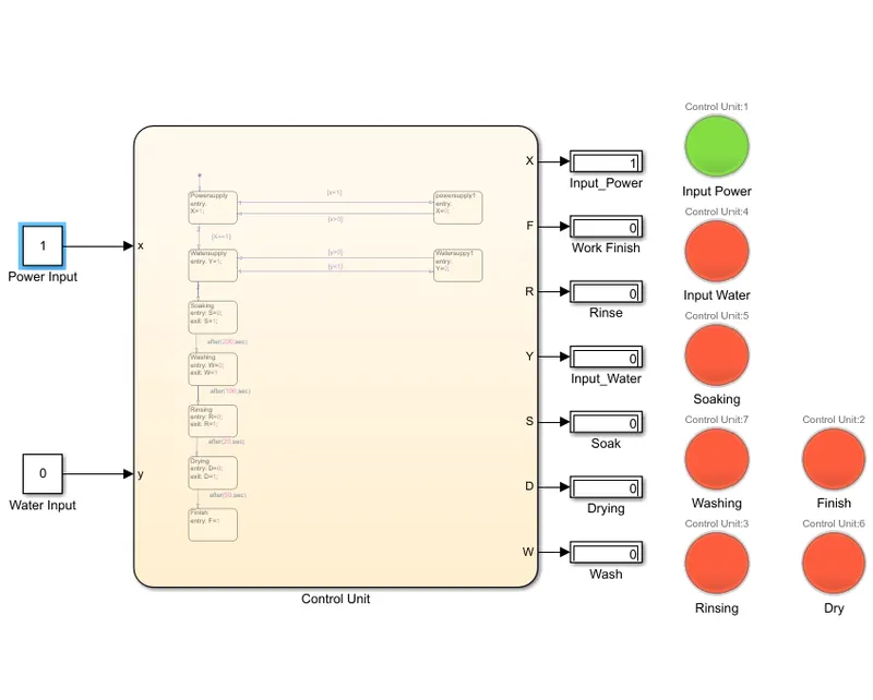
When Power Supply is ON but no Water Supply:
The two inputs are given for the power and water supply. Once the inputs are given, outputs are displayed by the flow chart as per the given sequence. The system is observed for some time then it is checked and the process is completed by green light as displayed or it is not completed any process, it displays the red light in the lamp.
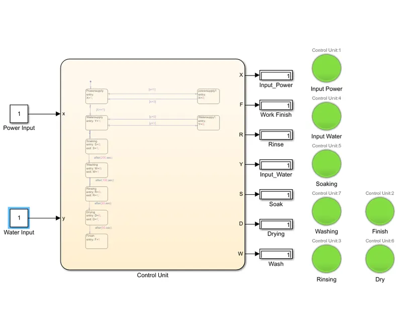
Result: Thus the control logic of the washing machine using a State Flow is processed as per the given sequences and LED lights are turned to green colours and the system is completed.
2. Gear Shift Logic:
Aim: Making a Simulink chart for the “Gear shift” logic.
Conditions:
Speed Range(kmph) Gear
0 to 15 1
16 to 25 2
26 to 40 3
41 to 60 4
Above 61 5
Give speed input while the simulation is running & display the gear number.
Procedure: A gear shift mechanism for a manual transmission includes a shaft axially movable for a selecting for engaging the gears defining the shift plans. The shaft is held in a reference shift plane by two helical springs.
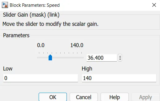
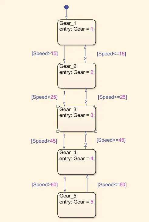
The Gearbox is constructed as per given conditions using Chart Block in which input is Speed and output is Gear. Input Speed is varied by using Slider Gain Block which is connected to Constant Block and Output is shown in Display Block and graph is shown by Scope Block.
Slider Gain Block:
Gearbox:
Model:
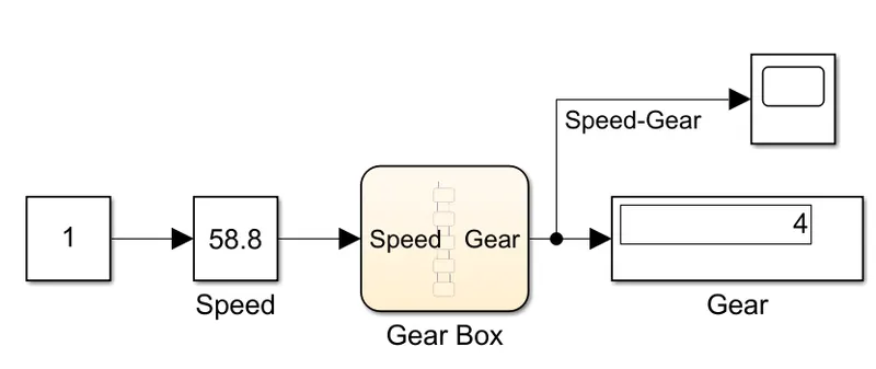
For Speed 58.8 km/hr the Gear shown is 4.
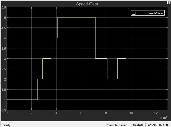
Result: A Simulink model is created for the gear shift logic and using slider gain the values are obtained.