Week - 4
Objective :
- Implimanation of control logic for " Washing machine " Using the provided State flow .
- implimentation Of the control logic for the " Gear Box " using the state flow provided .
- Checking and the validation if the system .
Conditions :
For Washing Machine :
- If the power supply is available, the system gets activated
- If the Water supply is not available, stop the process & indicate through LED
- Soaking time should be 200s followed by Washing time of 100s.
- Then rinsing happens for next 20s & dryer runs for 50s
For Gear Box :
-
Speed Range(kmph) Gear
0 to 15 1
16 to 25 2
26 to 40 3
41 to 60 4
Above 61 5
- Give speed input while the simulation is running & display the gear number.
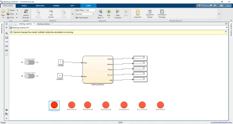
1. Simulink Model of the Washing Machine :
Control Logic And Flow chart :
Explaination :
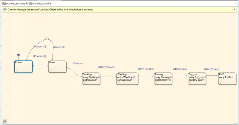
- For implimenting the control logic of the washing machine , i have created States as Power for power supply , Water supply as Water , Followed by Soaking , Washing , Rinsing and Dry Run States .
- Here i have applied one condition using Junction Point that the If the Power supply is on means 1 then and then only process will be proceed further to water supply .
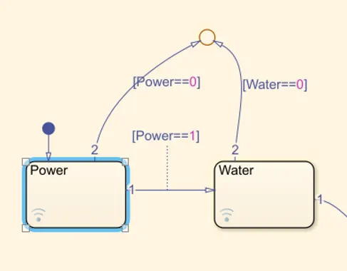
- Initially there was an error thrown in the Dignostics View , which can be seen below as ,
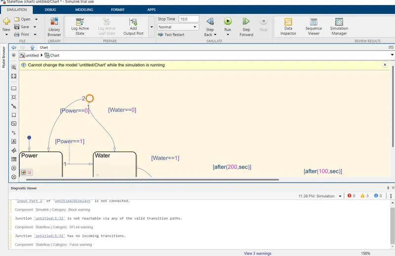
- Here i made direction of the Transition from power to Junction in the wrong direction which is coorected by Correcting the direction .
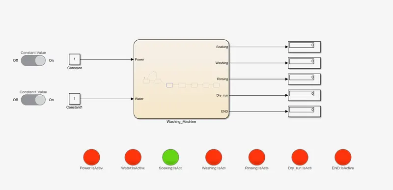
- After the water supply process is done , there will be Saoaking process For 200 seconds ,which will automatically will go to the next process .
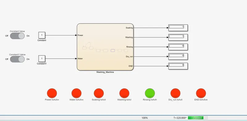
- Then there will be Washing process fro 100 seconds followed by the Rinsing process for 20 seconds .
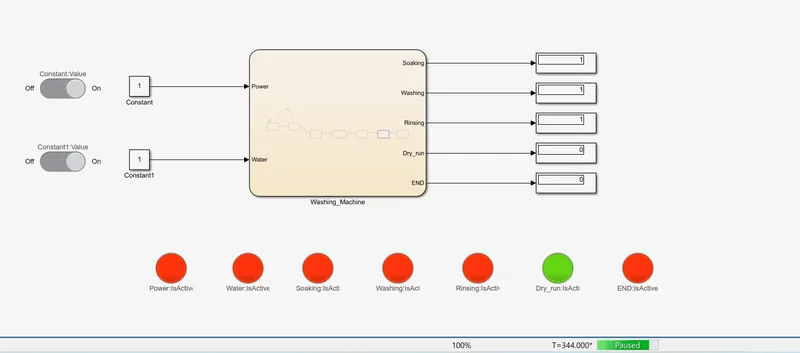
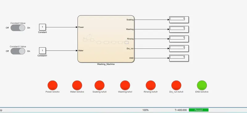
- and then finally Dry Run proceess will run for 50 seconds and then machine will stop .
- Then we have create the input and output through the left side symbol panel , where we have to define the input and the out put parametrs .
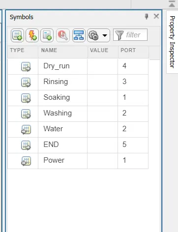
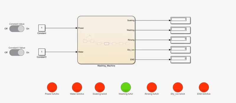
- For each process i have connected a lamp which will indicate processes .
- For making power supply on and off i have provided an slider Switch .
Results :
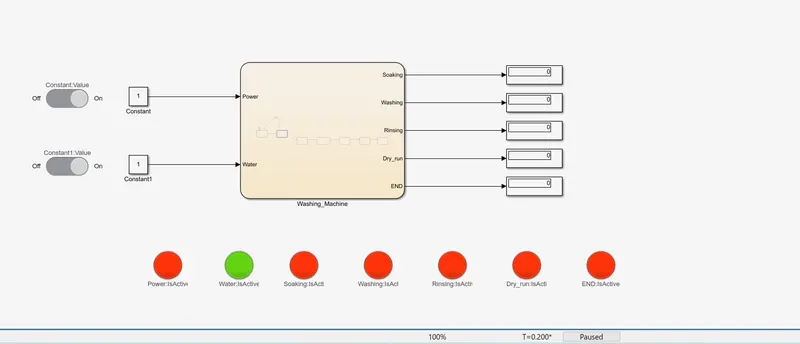
when Power and Water Supply is Off :
Both Power and water supply is on :
Soaking Process :
Washing Process :
Ringsing Process :
Dry Run Process :
Peocess End :
2. Implimenting the control logic for the Gear Box :
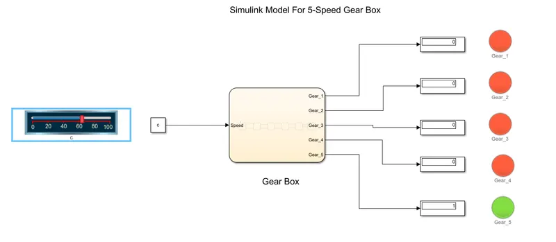
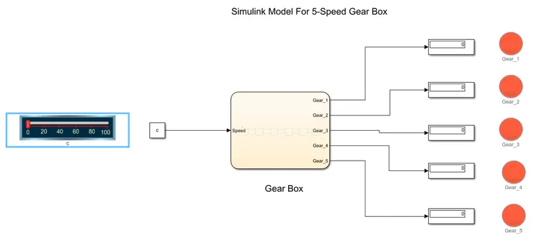
Simulink Model :
Logic Control and Flow Chart :
Explaination :
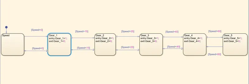
- For implimenting the Control logic for the Gear Box , we have to creat an various States as Gear 1 , Gear 2 , Gear 3 , Gear 4 and Gear 5 .
- For each Gear to Shift from one to other gear , i have made the Transition condition that 1st Gear will be activated when speed will go above the 0 and other conditions are also defined in the same way can be seen in above control logic model .
- I have provided reverse situation also , so that we can increase and decrease the speed as well .
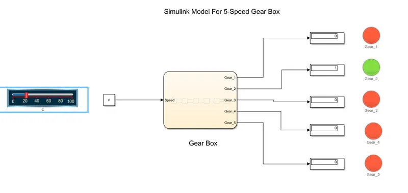
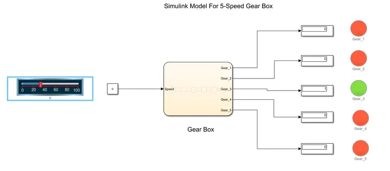
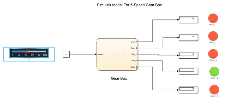
- Displays are added to indicate which gear is activated , here 1 means the respective gear is active and 0 means deactiveted .
- each Gear is connected with Lamp which will activeted whenever gear will be shifted .
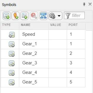
- Then Input and outputs are defined in symbol pannel as ,
Results :
- The Simulink Model is attached below .
- When 1st speed goes above 0 :
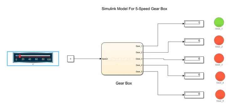
- Speed Greater than 15 :
Speed Greater than 25 :
Speed Greater than 40 :
Speed Greater than 60 :