Week - 4
Aim
Implement control logic of a "washing machine" and "Gear shift" using Stateflow.
Objective
Implement control logic of a"washing machine"using Stateflow as per given sequence.
1. If the power supply is available .the system gets activated
2. If the Wter supply is not available,stop the process & indicate through LED
3. Soaking time should be 200s followed by Washing time of 100s.
4. Then rinsing happens for next 20s & dryer runs for 50s
After all the processes have completed turn on the finished LED
Make a simulink chart for the "Gear shift" logic as per below conditions:
Speed Range(kmph) Gear
0 to 15 1
16 to 25 2
26 to 40 3
41 to 60 4
Above 61 5
State Flow :- Stateflow provides a graphical language that includes state transition diagrams.Flow charts
state transision tables and truth tables.It is used to descride how MATLAB algorithms and similunk models
react to input signals,events ,and time based conditions. Statflow enables you to design and develop
supervisory control task scheduling,fault management,communication protocols.User interfaces and
hybrid systems.With stateflow you model combinational and sequential decision logic that can be
simulated as a block within simulink model or executed as an object in MATLAB.Graphical animation
enables you to analysed and debug your logic while it is executing.Edit- time and run-time checks design
consistency and completess before implementation
Control Logic:- Control logic is key part of a software program that controls the operations of the
program. The control logic responds to commands from the users and it also acts on its own to perform
automated tasks that have been structured into the program.Control logic can be modeled using a state
diagram which is a form of hierachical state machine.
Procedure
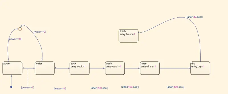
1. Create a chart block for defining the stateflow as per the given conditions.
2. Inside it the circular junction is to terminate the signal flow and return a null value.
3. If POWER IS OFF ie 0.The process is terminated at the junction else 1 is carry forwarded.
4. If water is OFF i.e 0.the process is terminated at the junction else 1 is carry forwarded.
5. After 200ses of soack block gets activated and soacking action taksplace.
6. After 200 sec of soaking wash blocks gets activated and washing action takes place.
7. After 100 sec of washing Rise block gets activated and rinsing action takes place
8. After 20 sec of rinsing. Dry block gets activated and drying action take place.
9. After 50sec of dry.Finish block gets activated.Finish is to terminate the signal flow in the process and
exist the chart.
10. Define power and water as inputs whereas soak,wash,rinse,dey,finish as outputs.
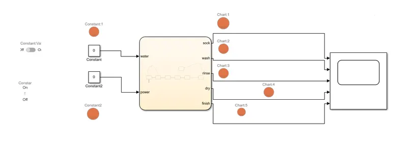
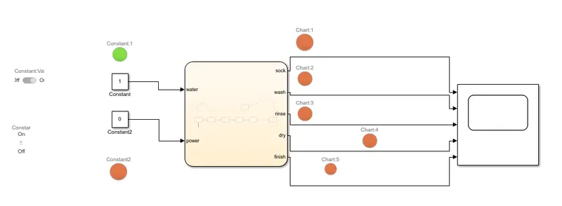
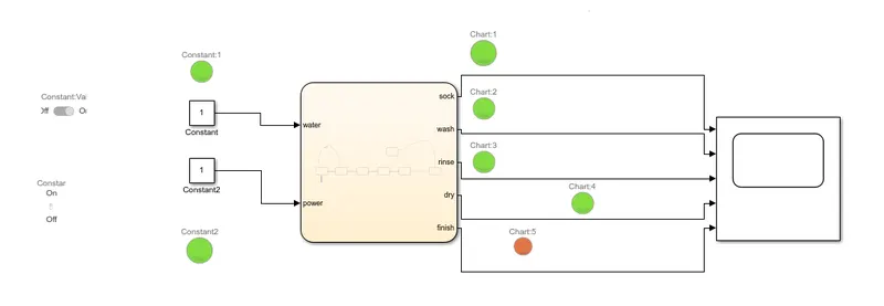
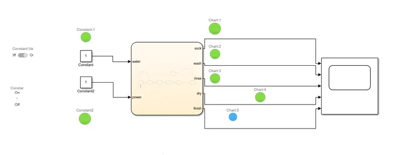
11. Connect the chart block with constant blocks power and water inputs.input switches connect to them
are slider switch and a toggle switch respectively. Attach lamps to observe the ON/OFF condition.
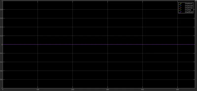
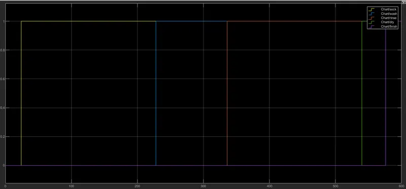
12. A common scope block is connested to observe the entire washing process and obtain the output,plot
Blue color in the lamp indicates that the process is complete.
Simulink Model
Washing Machine
State Flow
Scope:- When both switch are closed
Input:- 1
Power ON,Water OFF
PowerON , Wwter ON,t= 0sec
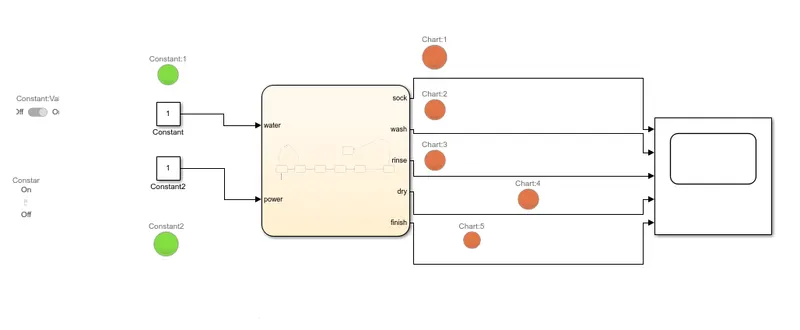
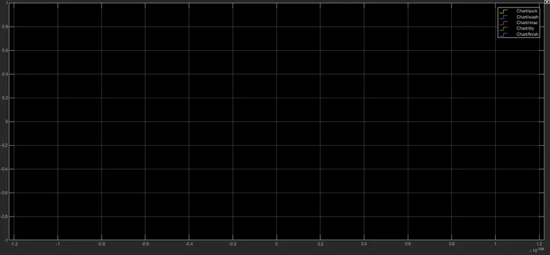
Power ON,Water ON,t=200s
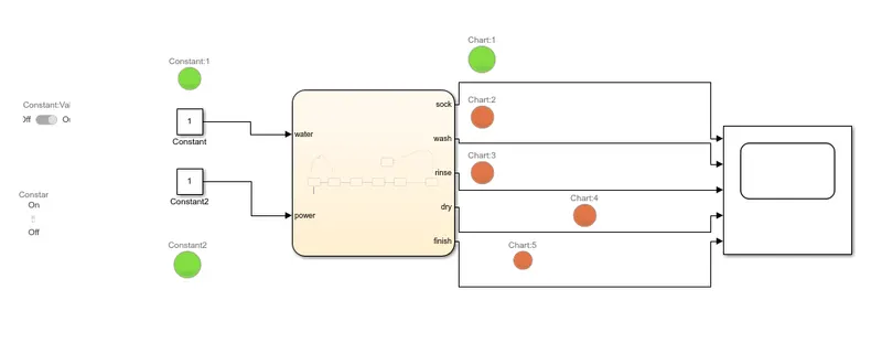
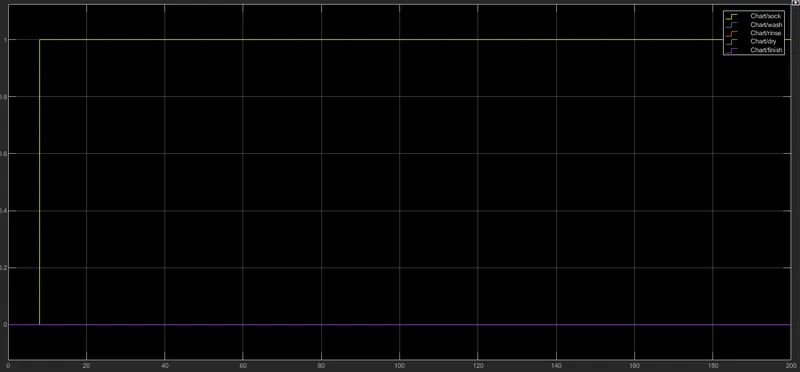
Power ON,Water ON,t=230sec
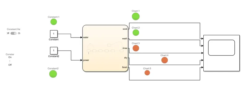
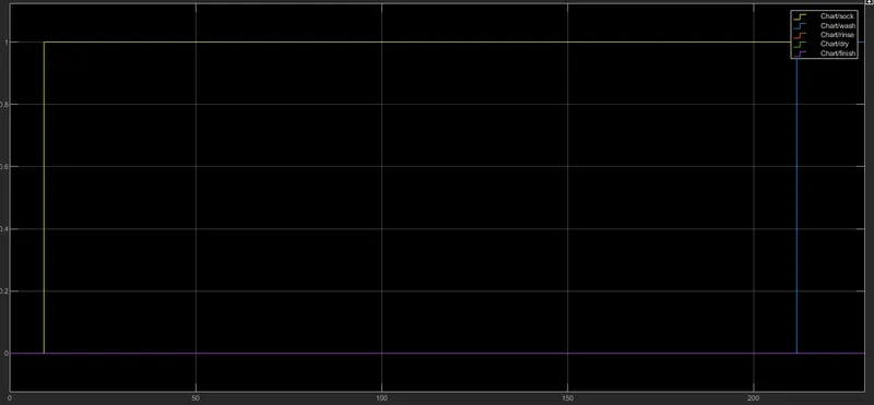
Power ON,Water ON,t=400sec
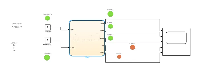
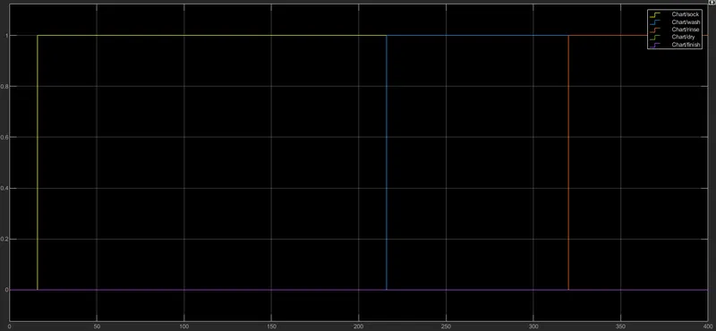
Power ON,Water ON,t=550sec
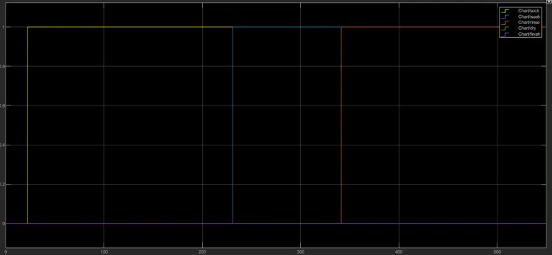
power ON,Water ON t=600sec
2. Gear Shift Mechanism
Make a simulonk chart for the "Gear Shift" logic as per below conditions
Speed Range(kmph) Gear
0 to 15 1
16 to 25 2
26 to 40 3
41 to 60 4
Above 61 5
Procedure
1. Create a chart block for defining the state flow as per the given conditions.
2. Inside it the circular junction is to terminate the signal flow and return null value.
3. If igntion IS OFF i.e 0.the process is terminated at the junction else 1 is carry forwarded.
4. If speed is less than or equal to 0.the flow is terminated abd rge gear 0 is activated at the junction
else 1 is carry forwarded.
5. If speed is greater than 0 or equal to 15.the flow is terminated and the gear 1 is activated.
6. If speed is greater than 15 or equal to 25. the flow is terminated and the gear 2 is activated .
7. If speed is greater than 25 or equal to 40. the flow is terminated and the gear 3 is activated .
8. If speed is greater than 40 or equal to 60. the flow is terminated and the gear 4 is activated .
9. If speed is greater than 60. the flow is terminated and the gear 5 is activated .
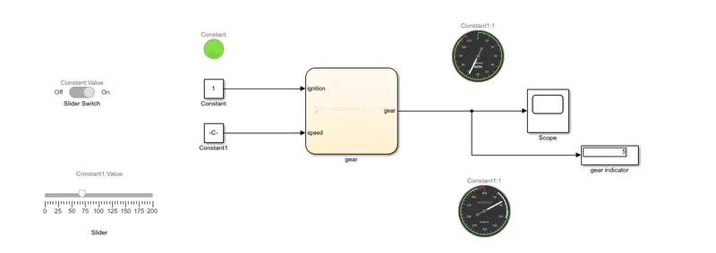
10. Define ignition and speed as inputs whereas speedometer,scope and gear number display as outputs
11. Connect the chart block with constant blocks power and water inputs.inputs switches connect to
them are slider switch and a toggle switch respectively. Attach lamps to observe the ON/OFF condition
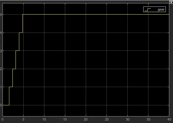
12. A common scope block is connect to observe the speed numerically and obtain the output plot.
Simulink model
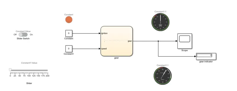
State flow

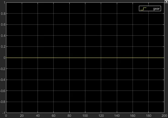
Ognition ON,Speed 0,Gear 0
Ignition ON,Speed 0-15,Gear 1
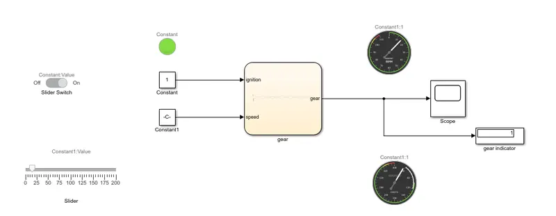
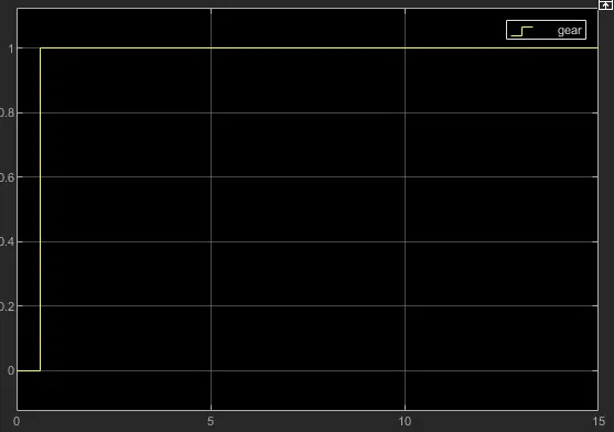
Ignition ON,Speed 16-25,Gear 2
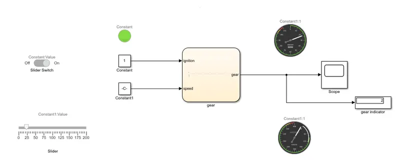
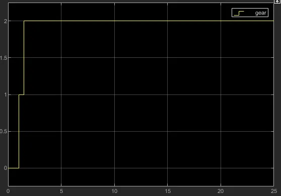
Ignition ON,Speed 26-40,Gear 3
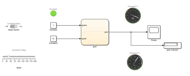
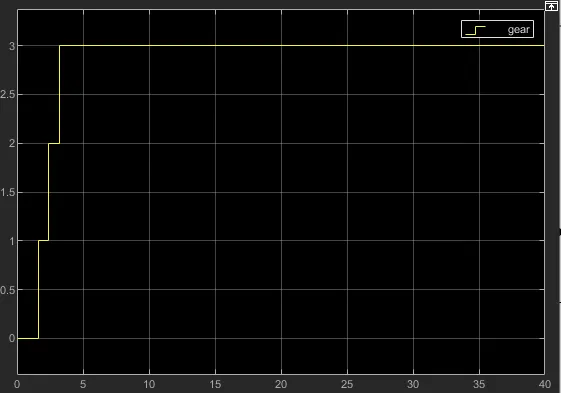
Ignition ON,Speed 41-60,Gear 4
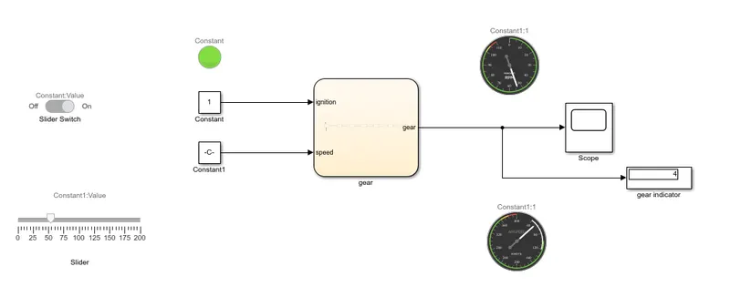
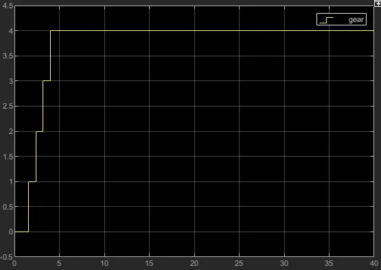
Ignition ON,Speed above 60,gear 4
Conclusion
Hence the problem was simulated for the washing machine and gear shift mechanism and executing the
state flow as per according to given conditions.
Googledrive Link
https://drive.google.com/drive/folders/1noW3Sz00YTUf_JKNmHY6yi-E5j3uz6-G?usp=sharing