Week - 4
1. Implementation of the control logic of a washing machine
Objective:
The objective is to implement the control logic of the washing machine using stateflow in matlab.
Blocks used:
These are some of the blocks used in this experiment
- Constant Block : This gives the constant value.
- Scope: This is used to view the output in graphical form.
- Lamp: This is used to indicate the state which is assigned to it.
- Chart: This is the main part of the state flow where we define the control logic
- States: These are the used to define the state.
- Variables: These are defined in the symbols pane to be used as variables.
- after(**,sec): This is one of the syntax used to give a desired delay in the system.
- entry:This is used to execute a certain instruction at the entry of the state.
- exit: This is used to execute a certain instruction at the exit of the state.
Model:
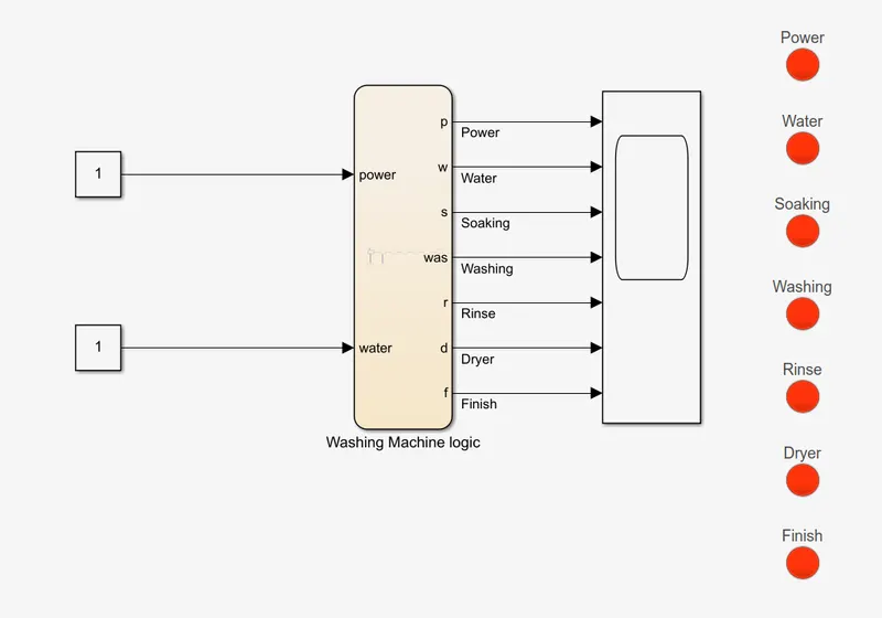
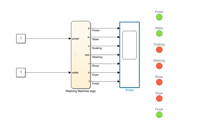
The below is the model required for this washing machine logic implementation.
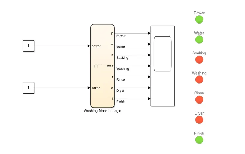
As per the requiement the inputs are power and the water indication which is provided by the constant block. As said that if the power is on and the water supply is correct the process should continue.
The chart block is used to define the specific logics which we need, where at each stage the output is taken in order to indicate the current working state.
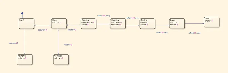
The above picture gives a direct understanding of the logics used, where the variables are used at each stages to determine the current state, even the delays are introduced wherever necessary.
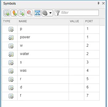
The variables type needs to be defined in the symbols pane in order to have correct types for the desired variables. We could get a idea from the type icon where the arrows indicate if it is input or output. The arrow indicating outside the icon suggests it is output, where the vice versa is input. Also the corresponding ports are assigned automatically.
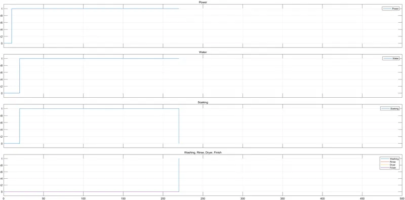
After the chart block we can see the scope block which is used to view the time based operation at a particular instant, which is then linked to the light switch.
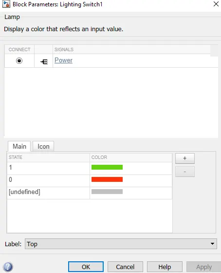
We need to define the state and corresponding colour that is to be displayed.
Observation:
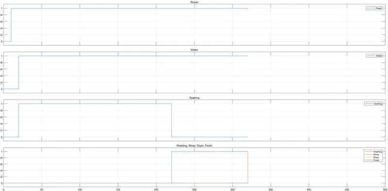
At the 0th instant the values are zero thus the lights are red in colour.
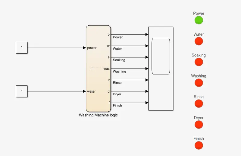
At the 1st instant we can see that the power light is green indicating that the power is available.
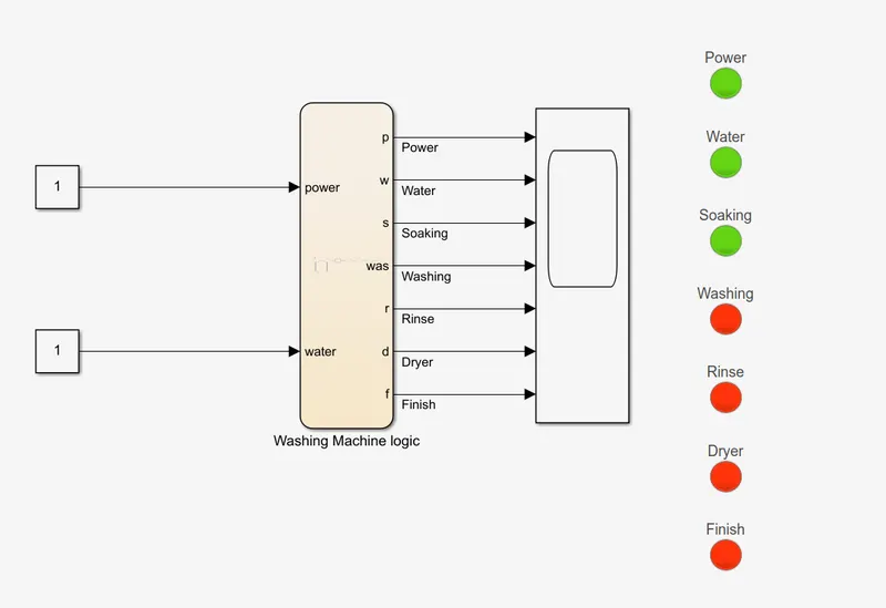
We could see in the next instant the water is also turned green

Also since the water and power is available the soaking process is started.
After the defined 200 sec of soaking the next process is started i.e washing which can be seen in the last part of the graph.
After 100 sec the next process is started which is rinsing, which is also seen in the last part of the graph.
Also when we see inside the chart we could see that the current state is highlighted in blue around the rinsing state.
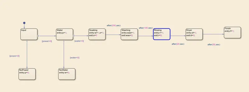
After the rinsing, dryer is the last state after that the logic is completed.
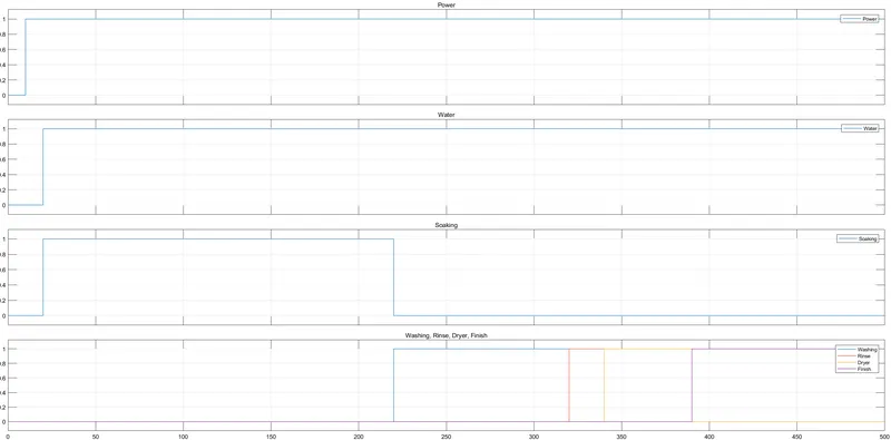
This is the finished state.
Now lets try with the power supply as 0.
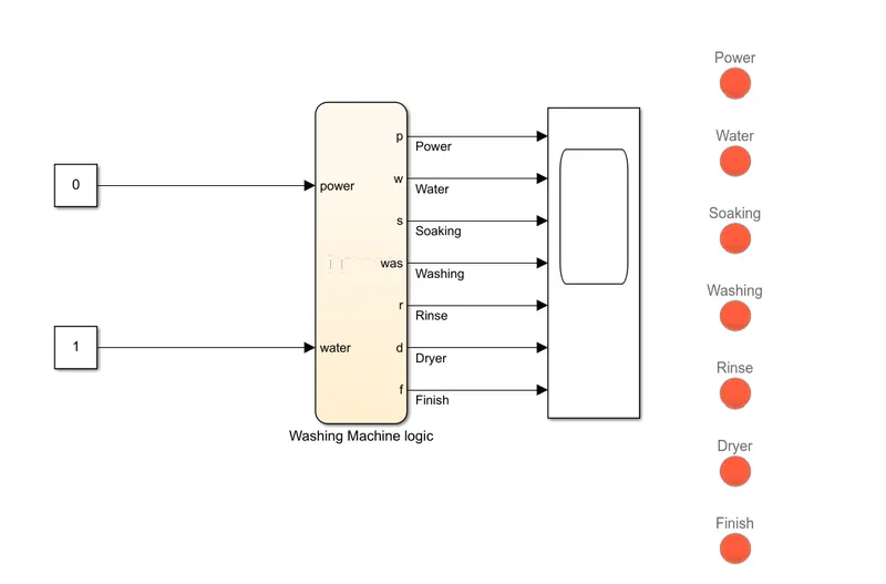
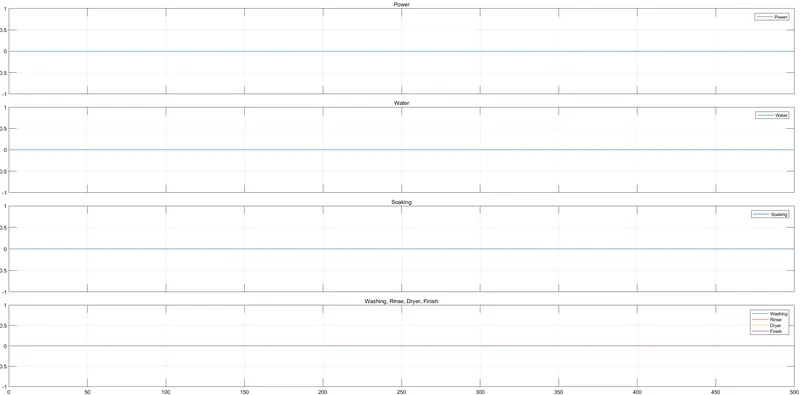
we can see that the the process is not started because of the power not available.
The next case is that we have power but no water, let see how the model responds
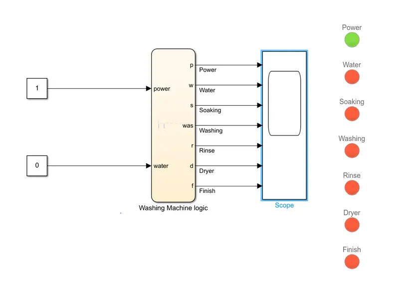
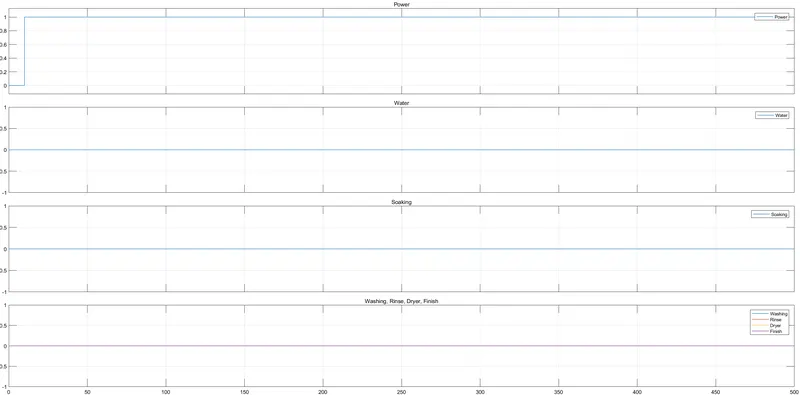
We could see that only the power light is green and other are red, which says that the power is only available.
Result:
Thus the control logic of the washing machine is implemented using the stateflow with the defined logic flow, and also implement the test case of no power and no water and the corresponding observations has been made.
2.Gear Shift logic
Objective:
Here we are going to implement the gear shift logic using the stateflow.
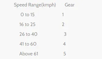
the above snap is the range of the speed for a particular gear.
Blocks Used:
- Horizontal Slider: This is used for the changing the values in realtime.
- Constant:This gives a constant value.
- Display:Used to view the output in numerical form.
- Chart: This is the main part of the state flow where we define the control logic
- States: These are the used to define the state.
- Variables: These are defined in the symbols pane to be used as variables.
- entry:This is used to execute a certain instruction at the entry of the state.
Model:
Now we need to change the Stop time to "INF", since we are going to simulate the realtime values.
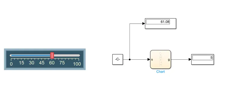
From the picture we can see that the constant block is connected to the chart which has the gear shift logic as required, the output of the chart is connected to the display.
The horizontal slider is connected to the constant block.
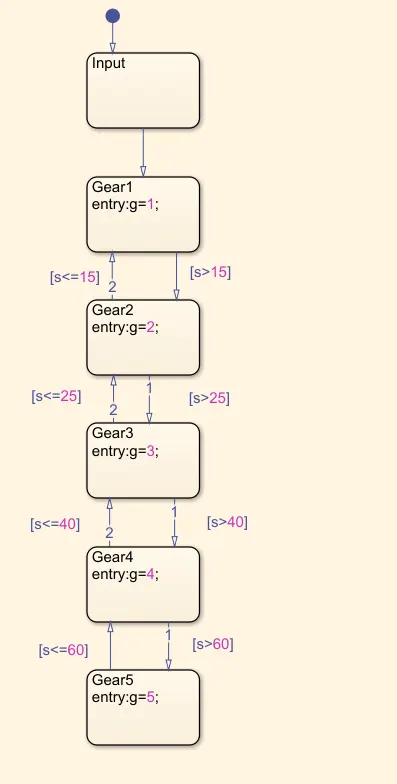
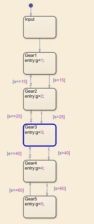
Inside the chart we can see the flow of logic.
Observation:
When the speed is varied by the horizontal slider that is given as the input to the state, we could see the change in the input via the input display and the gear is shown in the output display block.
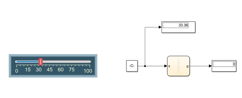
For example lets keep the speed as the 33.36kmph, when this is set the the control flows through the states gear1 -> gear2 -> gear3 and the control stays in the gear3 state since the gear3 is in the range of 26 to 40kmph.
Result:
Thus the gear shift logic is implemented using the stateflow with the given values.