Week - 4
AIM:
The objectives of this challenge is ,
1.To design and simulate a washing machine operations in stateflow using control logic.
2. To design and simulate the gear changing mechanism in the stateflow chart.
WASHING MACHINE DESIGN:
The washing machine is used to wash clothes of different types like cotton,polyster,silk etc.,
Various operations involved in this process are soaking, washing, rinsing, drying.
The operations in autonomous washing machine works on time based. According to the question,
Soaking is for 200s, washing for 100s, rinsing for 20s and drier works for 50 sec ,the process completes here.
MODEL CREATION:
Stateflow chart is used here to describe the operations.
Transition arrows helps in moving from one operation to another .
The control logic is the condition for operation transition.
The chart in stateflow contains name of the operation, value that it get while entry and exit to and from of the chart.It also contains the value for the lamp/LED .
The en,ex are abbreviation of entry and exit.
The value and the name entered in the chart should match the lamp that is connected in the simulink window.
The name that you entering in the chart as well as in transition will appear in the symbols pane. You can edit your variable as input, output or local data.
Input, output ports are created according to it in the chart block.
EXPLANATION:
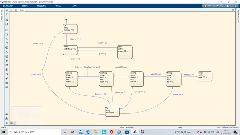
Chart1: Represents power supply block.
chart2:checks for water supply. If there is supply available it moves to chart4 or else moves to chart3.
Chart3: Indicates in lamp if there is no water supply.
chart4: It shows the soaking operation followed by chart5, chart 6, chart7, shows washing, rinsing, drying operations respectively.
If the power is failed at any operation the chart Off gets activated and the endLED will glow to indicate.
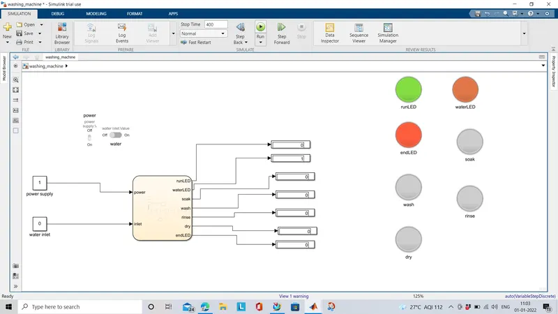
The power and water supply is given by constant block further it is connected to the rocker and sliding switches.
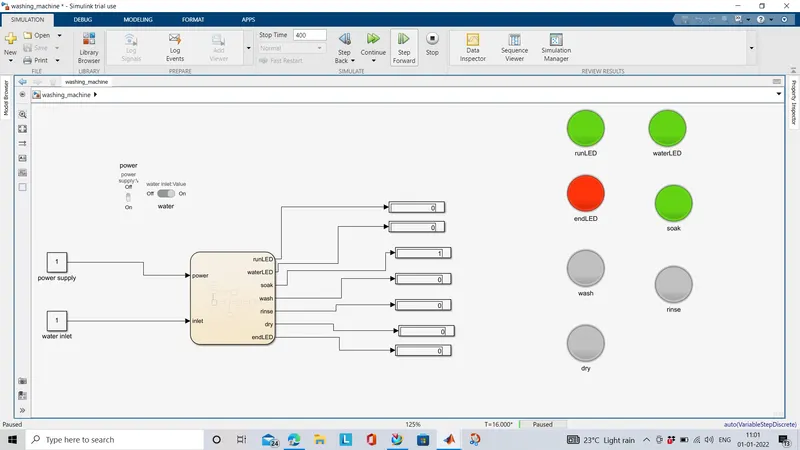
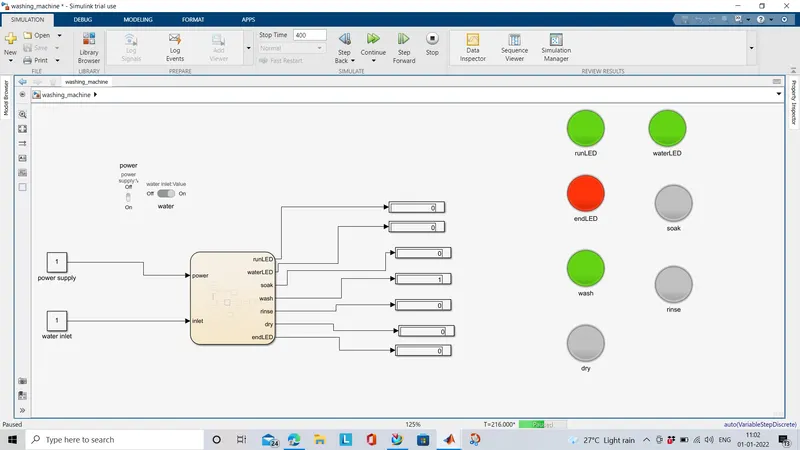
Each operations are connected to display to indicate its running.
At no water supply condition,
Soaking operation is running,
Performing washing operation for 100sec,
Drying operation for 50sec,
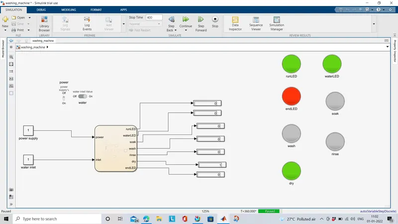
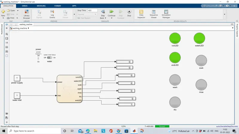
After completion all process ,it indicates green color in endLED.
GEAR SHIFT MECHANISM:
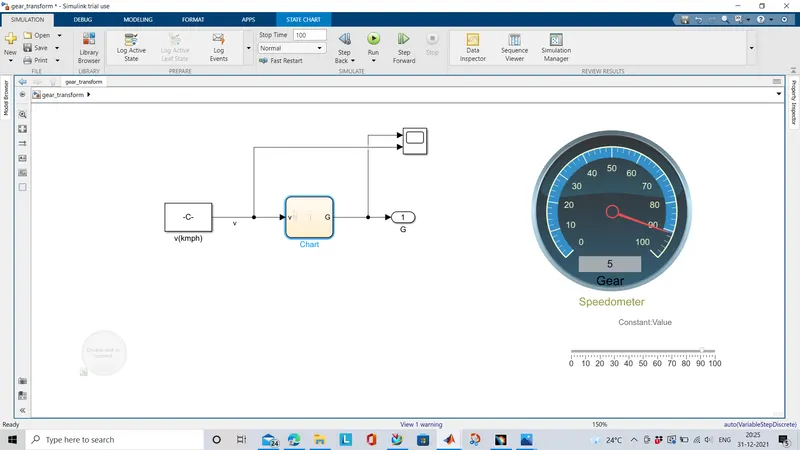
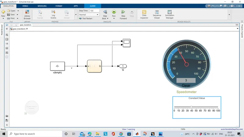
This model describes the gear shift mechanism using stateflow chart.
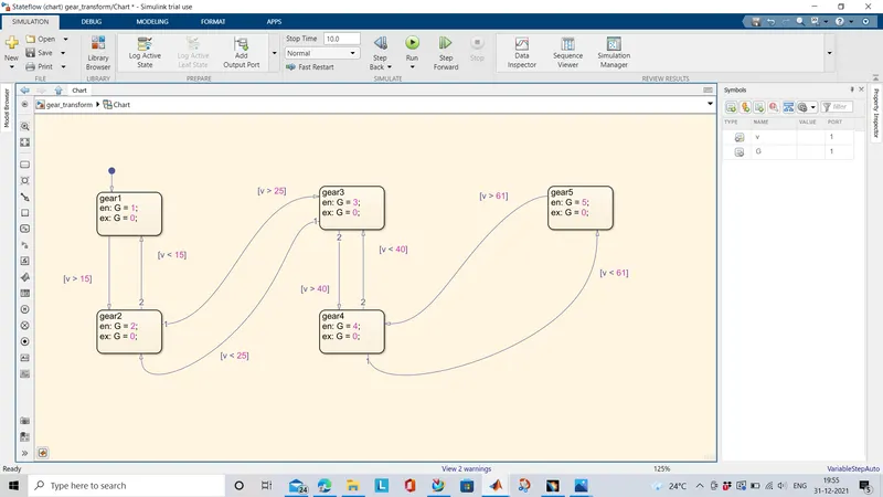
There art five charts in statefloww each representing respective gears. The gear shift is done when the vehicle reaches the threshold speed. According to question,
Speed Range(kmph) Gear
0 to 15 1
16 to 25 2
26 to 40 3
41 to 60 4
Above 61 5
Stateflow charts are created according to the above mentioned condition.
The velocity input is supplied from the constant block where it is further connected to the slider gain switch.
The input velocity and the corresponding gear shift are connected to the scope block.
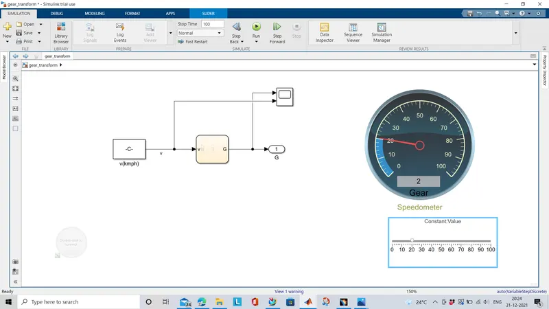
The speedometer indicates the input velocity and the display shows the current gear value for that speed.
CONCLUSION:
The stateflow chart with appropriate control logic is designed and simulated for washing machine and gear shift mechanism successfully using the simulink software.