Week - 4
1.
aim:
using the state flow implement a logic of " washing machine " with the flowing process of soaking ,washing ,rinsing and dryer
limitations of the logic:
1.system gets activated only if power is on
2.system gets deactivated if water supply is off
3.durations of the processes
a. soaking 200s
b. washing 100s
c. rinsing 20s
d. dryer 50s
block diagram of simulink model:
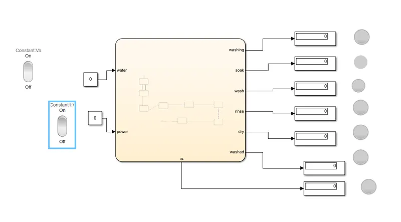
chart diagram of the model:
components used in the block diagram:
rocker switch:
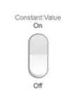
this rocker switch consists of two outputs operated manually by the operater
stateflow block:
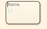
the block represents the stateflow block which individually represents particular state with set of operating functions
display:
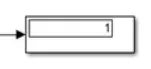
the above block is the display block which display the output of the signels
lamp:

the lamp is led output lamp which is operated by the output signels this can vary the indicated signel accoding to the given condition
inputs of the stateflow symbols:
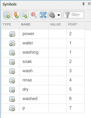
the above window represents the input and output block names namely symbolsof stateflow process
working of the simulink blocks:
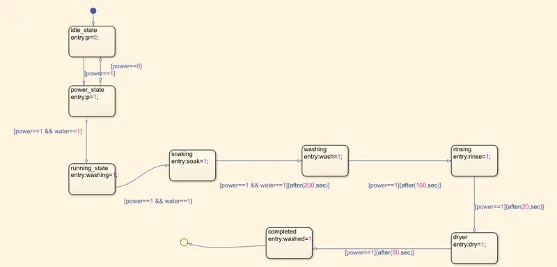
1. the main control logic of the model is embedded in the chart block which conditions and functions are situated
2.state block 1 represents the start of the logic followed by the two sets of condition, 1st conditions represents both power and water supply on where as 2nd conditions represents water supply off
3.1st set of conditions are followed by the states of soaking,washing ,rinsing and also dryer
4.soaking consist of two cases at entry and exit which is taking a time of 200s to complete this state
5.soaking is followed by the washing consisting sames case of entry and exit with duration of 100s
6.simillarly rinsing and drying takes time of 20s and 50 sec to complete the process
7.this chart block is follwed by the display block which diaplays the values of output signels sents by the states respectively
8. lamp is also connected to the output signel of the states in order to indicate the progress of the state
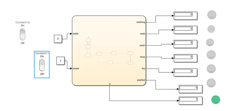
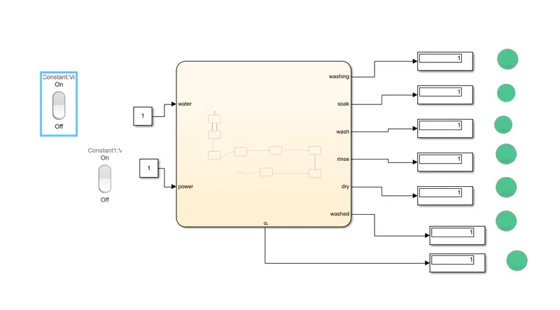
outputs:
1.if the water supply is not activated then stop the process and indicate LED signel
2.if the all the process are completed blow the end LED:
conclusion:
implementing of the control logic of washing machine according to given conditions can be performed by making use charts.these charts are a logical representation of the flowcharts which are divided in to different states flow process using these charts we can run a washing machine according to limitations given
2.
aim:
to implement simulink chart for "gear shift" using stateflow control logic
objectives:
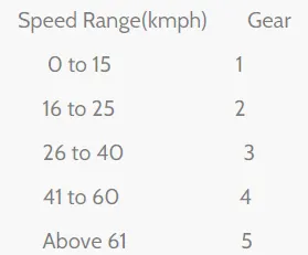
the above table represents the speed range in kmph and corresponding gear changes
block diagram of the simulink model:
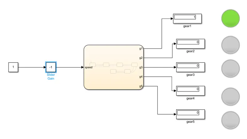
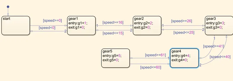
chart diagram of the model:
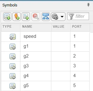
inputs of the stateflow symbols:
components used in the block diagram:
charts:
states are the state flow blocks which are used for the state wise operation using the condition
slider gain:
slider gain is a simulink block which is used to change the input while simulation is running
lamp:

a lamp is a simulink block which is used to blow the light signel according to the input of the signel
working principle of gear shift:
1.the chart block consists states such as gear1,gear2,gear3,gear4,gear5 which are changed according the input of the speed
2.the input speed is operated by the slider gain while simulation is taking place
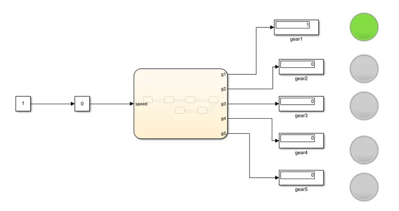
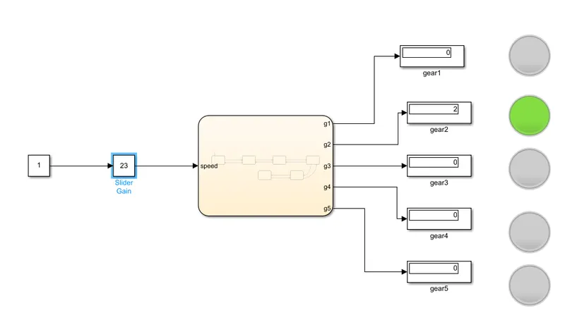
3.when speed is in between 1 to 15 kmph then gear one is operated shown in the display and blows the lamp,when speed in between 16 to 25 then gear 2 is operated and corresponding number is displayed
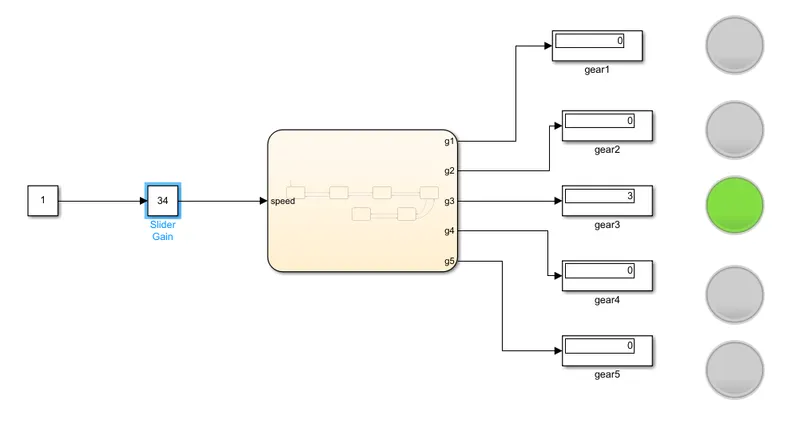
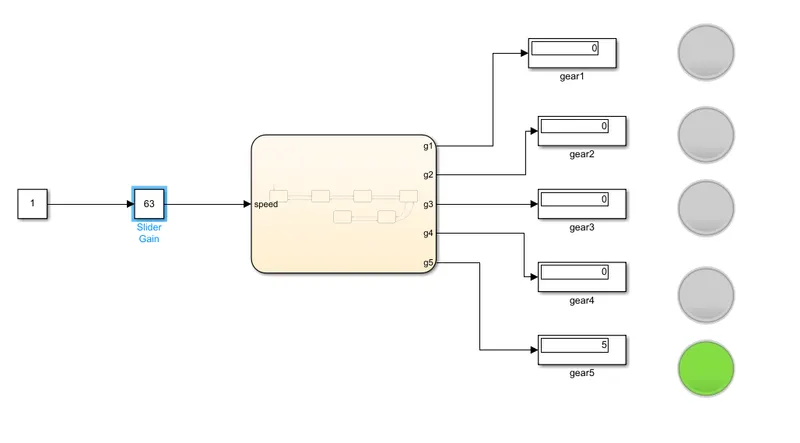
4.when its in between 26 to40 kmph it is operates on gear3 ,if it is in between 41 to 60 gear4 is activated similarly if it is above 61 final gear 5 is operated
outputs:
1.gear 1 condition:
2.gear 2 condition:
3.gear3 condition:
4.gear4 condition:

5.gear5 condition:
conclusion:
the control logic of the gear shift is based on using the charts .this charts contains state block in which each state gets a seperate operation and followed by the set of conditions provided this logic of gear shits is linear logic according variational speed provided by the slider gain gear box changes its state from one gear to another gear.